
User Guide


8
LED Meters
If wanting to calibrate the LED meters, the PEAK METER CAL dial on the rear panel can be used. In the default state, with the dial in
a central (‘detented’) position, 0dBFS is equal to +dBu. Rotating the dial in either direction sets a new value for 0dBFS from +8dBu
(fully anticlockwise) to +6dBu (fully clockwise).
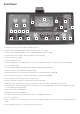
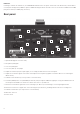
Rear panel
Optional ADC (digital conversion card)
Microphone (XLR) Input
Line-level (XLR) Input
Line-level (TRS /” Jack) Input
Outputs the main mic/line/inst input signal, as selected by the INPUT switch on the front panel
Outputs the instrument signal connected to the DI Input on the front panel (regardless of whether INST is selected using the
INPUT switch)
Calibrates the Peak Meters (see the previous section for details)
Transmits (SEND) and receives (RETURN) the main mic/line/inst input for additional signal processing. The INSERT switch on
the front panel should be active when in use. Both connectors are /” TRS Jack
Allows an external mono signal to be connected using a /” TRS Jack, for monitoring or converting to digital format
Allows an external stereo signal to be connected using two /” TRS Jacks, providing a monitor mix for a recording artist
Calibrates the VU Meter (see the previous section for details)
Mains IEC connector
Power switch
.
.
.
.
5.
6.
7.
8.
.
0.
.
.
.
1
2
3
4
56
7
8
9
10
11
12
13