
User Guide


Analogue inputs
The MIC I/P (XLR) and LINE I/Ps (XLR and ¼” TRS Jack) can be used to connect an analogue source to ISA One. If a microphone is
connected to the MIC I/P, phantom power can also be supplied by making sure MIC is selected using the INPUT switch on the front
panel, then activating the +8V switch. If you are unsure whether your microphone requires phantom power, refer to its handbook,
as it is possible to damage some microphones (most notably ribbon microphones) by providing phantom power.
If wanting to record a Line-level signal then you have the choice of using an XLR or balanced Jack connector. Once connected, simply
use the INPUT switch on the front panel to select LINE.
The remaining analogue inputs are for an external mono signal (EXT I/P) and stereo signal (CUE MIX LEFT/RIGHT). The mono
signal connected to EXT I/P is summed with the main input signal and sent to the headphones for monitoring, as well as being sent
independently to the second channel of the optional ADC, if installed. (See the Digital Options or Monitoring Options sections for
details.) The stereo signal connected to CUE MIX can be routed to the headphones by activating the CUE MIX switch on the front
panel. (See the Monitoring Options section for details.)
Analogue outputs
There are two analogue outputs on the rear panel of ISA One. The MAIN O/P (channel ) and the DI O/P (channel ). The rst channel
relates to the main input signal being processed, and is selected using the INPUT switch on the front panel. The second channel is
always the instrument signal that is connected to the DI input on the front panel.
Insert
The two INSERT connectors are for sending and returning the main mic/line/inst signal to and from an additional processor, like
a compressor. Connect SEND to the input of the additional processor and RETURN to its output, preferably with balanced cables
as both inputs are ¼” TRS Jack. Make sure that the INSERT switch is activated on the front panel if using the Insert facility, so that
the RETURN signal is routed to the meters (with the POST INSERT switch engaged), MAIN O/P and channel of the optional ADC (if
installed). For more information on using the ISA One Insert, see the INSERT section in the Front Panel Overview.
Digital options
ISA One can be used as a high quality two-channel ADC to convert analogue signals to various digital formats (AES, S/PDIF and
ADAT), by installing the optional digital output board (ADC). The optional ADC can be retrotted to a standard ISA One at any time.
No engineering experience is required as the card can be tted easily by the user. Full tting instructions for this option are included
along with the ADC.
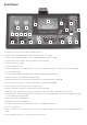
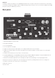
Word clock In and Out (BNC connectors)
Optical/TOSLink Digital Outputs (ADAT and S/PDIF)
AES or S/PDIF Select Switch for the -pin Digital Output
-pin Digital Output (AES or S/PDIF, selected by the adjacent switch)
Selects -wire or -wire mode across the -pin Output to allow ISA One to be connected to older digital equipment
.
.
.
.
5.
1
2
3
4
5