
User Manual


6
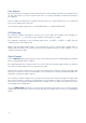
Rear Panel
12
13
1516
17
14
The remainder of the Scarlett OctoPre’s inputs and outputs are on the rear panel.
12. INPUTS 3 to 8 – 6 x “Combo XLR” connectors; note that the inputs for Channels 3 to 8 do not
have INST mode, but are otherwise identical to those for Channels 1 and 2.
13. ADAT OUT – two TOSLINK connectors providing the digital outputs of the unit. Utilisation of
the two connectors is sample rate-dependent, as follows:
Sample Rate OUTPUT 1 (RH port*) OUTPUT 2 (LH port*)
44.1/48 kHz Channels 1 to 8 Channels 1 to 8
88.2/96 kHz Channels 1 to 4 Channels 5 to 8
176.4/192 kHz Channels 1 & 2 Channels 3 & 4
* As viewed looking at rear panel
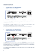
14. LINE OUTPUTS 1 to 8 – eight balanced analogue line outputs on ¼” 3-pole (TRS) jack sockets.
These connectors are always active, and carry the outputs of Channels 1 to 8, enabling the
Scarlett OctoPre to be used as a stand-alone, high quality 8-channel analogue mic pre.
15. WORD CLOCK OUT – a BNC connector carrying the Scarlett OctoPre’s word clock signal;
this may be used to synchronise other digital audio equipment forming part of the recording
system. The source of sample clock synchronisation is selected by the SYNC switch [8].
16. WORD CLOCK IN – a BNC connector for the connection of an external word clock signal;
select by setting SYNC to WORD. Use this input if you have a master reference clock which
provides synchronisation for all the digital audio devices in your studio.
17. AC mains – standard IEC receptacle. The Scarlett OctoPre is fitted with a “Universal” power
supply, and will run from any AC mains voltage from 100 to 240 V, at 50 or 60 Hz.