
User Manual


14
HARDWARE FEATURES
Front Panel
1
2
974
3
6 85
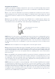
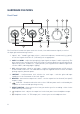
The Front Panel includes the input connectors for Mic, Line and Instrument signals, as well as
the input gain and monitoring controls.
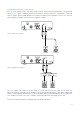
1. Inputs 1 & 2 – “Combo” type input sockets - connect microphones, instruments (e.g., guitar),
or line level signals via XLR or ¼” (6.35 mm) jacks as appropriate.
2. GAIN 1 and GAIN 2 – adjust the input gain for input signals on inputs 1 and 2 respectively. The
gain controls have concentric bi-colour LED ‘rings’ to confirm signal level: green indicates an
input level of at least -24 dBFS (i.e., ‘signal present’), the ring then turns red when signal level
reaches 0 dBFS, indicating digital clipping.
3. 48V – phantom power switch for mic inputs - enables 48 V phantom power at XLR contacts
of both Combo connectors. The CM25 MkII microphone supplied with the Scarlett 2i2 Studio
package requires phantom power.
4. LINE/INST – Line/Instrument level switches for each input – switches gain and input
impedance to suit instrument or line level signals.
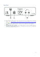
5. MONITOR – main monitor output level control - sets the output level at the main (rear panel)
outputs 1 and 2.
6. USB LED – illuminates when the unit receives USB bus power and is confirmed by the
computer as connected and operating correctly.
7. DIRECT MONITOR – allows you to select how you monitor your live recording - either via the
DAW or directly (zero latency).
8. Headphone level – adjusts the output level at the front panel stereo headphone output.
9. Headphone socket – ¼” TRS output jack - connect your stereo headphones here.