
User guide


14
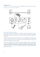
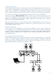
The line output connectors are standard phono (RCA) sockets. Typical consumer (hi-fi) amplifiers
and small powered monitors will have inputs on phono (RCA) sockets or a single 3.5 mm 3-pole jack
plug (intended for direct connection to a computer). In either case, use a suitable connecting cable
with phono plugs (RCA jacks) at one end.
NOTE: You run the risk of creating an audio feedback loop if loudspeakers are active at the same time
as a microphone! We recommend that you always turn off (or turn down) monitoring loudspeakers
while recording, and use headphones when overdubbing.
HARDWARE FEATURES
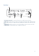
Front Panel
3 4 6 9
1 2 5 7 8
The front panel includes the input connectors for mic and instrument signals, and the input gain and
monitoring controls.
1. Input 1 - electronically balanced input via 3-pin XLR socket for microphones.
2. GAIN 01 - adjust the gain for the microphone signal on input 1. The gain control has a concentric
bi-colour LED ‘ring’ to confirm signal level: green indicates an input level of at least -24 dBFS
(i.e.,‘signal present’), the ring then turns red when signal level reaches 0 dBFS.
3. 48V - phantom power switch for mic input - enables 48 V phantom power at the XLR socket.
4. Input 2 - unbalanced input for connecting instruments; ¼” TS jack socket.
5. GAIN 02 - adjust the gain for the instrument signal on input 2.
6. MONITOR - main monitor output level control - sets the output level at the main (rear panel)
outputs 1 & 2 and the front panel headphone output.
7. USB LED - illuminates when the unit in connected and receives power via the USB connection.
8. DIRECT MONITOR - selects monitoring of input signals to be directly from inputs (On) or via DAW
(Off).
9. Headphone socket - ¼” TRS output jack - connect your stereo headphones here.