
User Manual


7
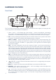
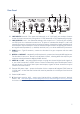
Rear Panel
1415 12 10
1016
17
11
13 11
10. LINE INPUTS 3 and 4 – The inputs are balanced, on ¼” (6.35 mm) jack sockets. Connect
further line level sources here, using either ¼” TRS (balanced) or TS (unbalanced) jack plugs.
11. LINE OUTPUTS 1 to 4 – four balanced analogue line outputs on ¼” (6.35 mm) jack sockets;
use TRS jacks for a balanced connection or TS jacks for unbalanced. Outputs 1 and 2 will
normally be used to drive the primary monitoring system, though the signals available at all
these outputs may be defined in Focusrite Control. Outputs 3 and 4 can typically be used for
driving alternative speakers (i.e., midfield, nearfield, etc.), or to drive outboard FX processors.
12. USB 2.0 port – Type B connector; connect the Scarlett 6i6 to your computer with the cable
supplied.
13. MIDI IN and MIDI OUT – standard 5-pin DIN sockets for connection of external MIDI equipment.
The Scarlett 6i6 acts as a “Break-out (and Break-in) Box”, allowing MIDI data to/from your
computer to be distributed to additional MIDI devices.
14. SPDIF IN and OUT – two phono (RCA) sockets carrying two-channel digital audio signals in
or out of the Scarlett 6i6 in S/PDIF format. These are essentially Inputs and Outputs 5 and 6
to/from the unit. Like all the other inputs and outputs, signals at these connectors may be
routed in Focusrite Control.
15. External DC power input – power the Scarlett 6i6 via a separate AC adaptor (PSU) rated at
12 V DC and 1 A. Note that the Scarlett 6i6 canot be powered via its USB port from the host
computer.
16. Power On/Off switch.
17. K (Kensington security lock) – secure your Scarlett 6i6 to a suitable structure if desired.
Please see www.kensington.com/kensington/us/us/s/1704/kensington-security-slot.aspx
for further information on how to use this feature.