
Installation Instructions
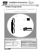

2
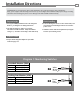
Installation Directions
1. If using the LCBMA (Latchbolt monitor & Locking Cam
Monitor), see Diagram 1 for wiring instructions.
2. The strike body ships as either a 12 or 24 volt
unit and is not field selectable. Verify the available
voltage is +/- 10% of the rated voltage of the strike body.
Prepare Strike
CAUTION! Before connecting any device at the installation site, verify input voltage using a multimeter.
Many power supplies and low voltage transformers operate at higher levels than listed. Any input voltage exceeding
10% of the solenoid rating may cause severe damage to the unit and will void the warranty.
Prepare Frame
Finish Installing
4. Connect the Plug In Connector to the electric strike, and
connect wires from the Plug In Connector leads to the
power source.
5. Install the electric strike unit in jamb cutout, using the
#12-24 x 1/2” mounting screws.
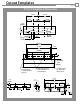
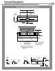
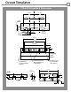
3. Prepare frame using the template for your strike
located on pages 3-7.
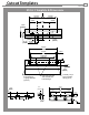
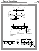
Diagram 1: Monitoring Switches
Latchbolt Monitor (LBM)
White
Orange
Normally Open
Green
Normally Closed
Common
Locking Cam Monitor (LCM)
Brown
Blue
Normally Open
Yellow
Normally Closed
Common
White
Orange
Green
Brown
Blue
Yellow