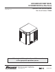
HCD/HMD/HCF/HMF1000R, HCD/HMD1000N Ice Machines Order parts online www.follettice.com Operation and Service Manual After Serial Number C20000 208264 tion e Plat tifica ule k Mod Stoc No. ule Mod uct Prod No.
Horizon 1000R/N Ice Machines
Table of contents Welcome to Follett Corporation .................................................................................................................................. 4 Specifications .............................................................................................................................................................. 5 Operation.................................................................................................................................................
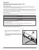
Welcome to Follett Follett equipment enjoys a well-deserved reputation for excellent performance, long-term reliability and outstanding after-the-sale support. To ensure that this equipment delivers the same degree of service, we ask that you review the installation manual (provided as a separate document) before beginning to install the unit. Our instructions are designed to help you achieve a trouble-free installation.
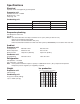
Specifications Electrical Separate circuit and equipment ground required. Evaporator unit Standard electrical – 115/60/1 Maximum fuse – 15A Amperage – 6A Condensing unit Single-Phase 3-Phase Electrical 208-230 V, 60 Hz 208-230 V, 60 Hz Maximum Circuit HVACR breaker size 15A 15A Minimum Circuit Ampacity 10.7A 9.9A Evaporator plumbing 3/8" OD push-in water inlet 3/4" MPT Notes: 3/4" vented drain line must slope a minimum of 1/4" per ft (6 mm per 30.4 cm run). Drain to be hard piped and insulated.
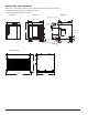
Dimensions and clearances Entire front of ice machine must be clear of obstructions/connections to allow removal. 1" (26 mm) clearance above ice machine for service. 1" (26 mm) minimum clearance on sides. Front View Side View Back View Ice transport hose connection 21.28" (541 mm) 19.3" (491 mm) L2 NEMA 5-15 right angle 23.50" (597 mm) G L1 5/8" suction line 15.56" (395 mm) 3/8" liquid line 21.05" (535 mm) 22.8" (580 mm) 6.95" (177 mm) 2.53" (65 mm) 1.75" (45 mm) min.
Operation Cleaning and preventive maintenance (all models) Note: Do not use bleach to sanitize or clean the ice machine. Preventive maintenance Periodic cleaning of Follett’s ice machine system is required to ensure peak performance and delivery of clean, sanitary ice. The recommended cleaning procedures that follow should be performed at least as frequently as recommended, and more often if environmental conditions dictate.
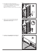
Fig. 2 2. Mix 1 gallon (3.8 L) 120 F (49 C) water and 7 oz (198 g) (one 7 oz packet of Follett SafeCLEAN ice machine cleaner, P/N 00132001). Locate cleaning cup. Fill until HI WATER light comes on (Fig. 2). HI WATER Note: Do not use bleach to sanitize or clean the ice machine. Fig. 3 3. Replace cover on cleaning cup. Wait until machine restarts. Machine will clean, then flush 3 times in approximately 12 minutes (Fig. 3). 12 Fig. 4 4. To sanitize – Press CLEAN button. The machine will drain.
Fig. 5 5. Mix 1 gallon 120 F (49 C) water and 1.6 oz (48 ml) NU-CALGON IMS-II SANITIZER. Fill until HI WATER light comes on (Fig. 5). Note: Do not use bleach to sanitize or clean the ice machine. HI WATER Fig. 6 6. Replace cover on cleaning cup. Wait until machine restarts. Machine will sanitize, then flush 3 times in approximately 12 minutes (Fig. 6). 12 Fig. 7 7. To clean transport tube – Press power switch OFF (Fig. 7).
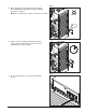
Fig. 8 8. Disconnect coupling as shown (Fig. 8). Fig. 9 9. Using disposable food service grade gloves, insert dry Sani-Sponge™ (kit P/N 00132068). Next, insert SaniSponge soaked in Nu-Calgon IMS-II sanitizer solution. Push both Sani-Sponges down ice transport tube with supplied pusher tube (Fig. 9). (40 16" 7m m 1 2 ) 3 Fig. 10 10. Remove and discard 16” (407 mm) pusher tube (Fig. 10).
Fig. 11 11. Reconnect coupling. Press power switch ON. Ice pushes Sani-Sponges through tube (Fig. 11). Fig. 12 12. Place a sanitary (2 gallon or larger) container in bin or dispenser to collect Sani-Sponges and ice for 10 minutes. Collect 5.5 lb (3 kg) of ice from unit. Discard ice and Sani-Sponges (Fig. 12).
Service Ice machine operation (all models) Follett’s ice machine consists of five distinct functional systems covered in detail as follows: • Water system • Electrical control system • Mechanical assembly • Refrigeration system • Bin full The Horizon ice machine overview The Follett Horizon ice machine uses a horizontal, cylindrical evaporator to freeze water on its inner surface. The refrigeration cycle is continuous; there is no batch cycle.
Water system The water level in the evaporator is controlled by a feed solenoid and level detecting sensors. Referencing the diagram below, water sensing rods extend down into the reservoir at the end of the evaporator assembly. The system works via electrical conductivity as follows: One of the longest probes is a common. When water is between any of the other probes and the common, the PC board will sense the activation.
Electrical system Normal control board operation The PC board indicator lights provide all the information necessary to determine the machine’s status. Green indicator lights generally represent “go” or normal operation; Yellow indicators represent normal off conditions; Red indicators generally represent alarm conditions, some of which will lock the machine off. A green light labeled POWER indicates power to the machine.
Test points: The Horizon PC board incorporates on-board test points that can be used to determine various electrical outputs. The test point holes allow a standard probe to be inserted for quick voltage measurement. Error faults: The Horizon PC board monitors various operating parameters including high pressure, auger gearmotor amperage limits, clogged drain, and high and low water alarm conditions. There are two types of errors namely “hard” or “soft”.
Gearmotor data (Brother) Gearmotor current 5.
Single-phase condensing unit wiring diagram IMPORTANT: COMPRESSOR EQUIPPED WITH AN INTERNAL OVERLOAD PROTECTOR. ALLOW TIME FOR RESET. USE COPPER CONDUCTORS ONLY.
Fig. 13 Mechanical system Evaporator disassembly 1. Press PURGE button to purge evaporator, and then turn power OFF. 2. Unscrew and remove stream divider as shown. Fig. 14 3. Unplug and remove gearmotor as shown. 4. Remove all traces of petrol-gel from the auger shaft. Fig. 15 5. Unscrew and disconnect transport tube from louvered docking assembly. 6. Unplug sensor at the electrical box. 7. 18 Remove vent tube from shuttle housing as shown.
Fig. 16 8. Unscrew and disconnect transport tube from louvered docking assembly. 9. Unplug sensor at the electrical box. 10. Remove vent tube from shuttle housing as shown. Fig. 17 11. Remove and discard mating ring and seal. 12. Carefully remove auger. Fig. 18 Evaporator reassembly 1. Remove and inspect O ring seal. Discard if damaged in any way. 2. Clean O ring groove. Lubricate O ring with petrol-gel and reinstall.
Fig. 19 3. Press new mating ring into main housing as shown. 4. Lube the shaft with liquid soap in the area shown and slip on seal and spring. Cardboard disc Note: Do not touch the sealing surfaces. Use cardboard disk to install. Lube with soap Do not touch Fig. 20 5. Reinstall main housing as shown. Fig. 21 6. Orient auger shaft with keyway in the upward position. 7. Force main housing into position against evaporator and place 1/4" (7 mm) diameter Phillips screwdriver into hole in the auger shaft.
Fig. 22 11. Reconnect transport tube to louvered docking assembly. 12. Plug sensor in at the electrical box. 13. Reconnect vent tube to the shuttle housing as shown. Fig. 23 14. Apply a coat of petrol-gel to the auger shaft. 15. Install gearmotor, making sure that insulation is properly seated between gearmotor and main housing as shown. 16. Firmly tighten four gearmotor bolts in place. Apply petrol-gel Fig. 24 14. Insert a bolt into the auger shaft and finger tighten. 15.
Fig. 25 17. Remove bolt and reinstall the washer and bolt. Place retainer over bolt and secure with nut and washer. Fig. 26 18. Lubricate body of stream divider with petrol-gel and reinstall. 19.
Refrigeration system Condenser unit operation The condensing unit is weatherproof and equipped to operate in ambient temperatures from -20 F to 120 F (-29 C to 48.9 C). The condensing unit is controlled by a low pressure control, which works in concert with a refrigerant solenoid valve on the evaporator module. On start-up, the refrigerant solenoid valve opens and suction pressure rises above the “on” set point of the control. The compressor and fan turn on and the refrigeration system operates.
Refrigeration system diagram high side service valve with service port filter drier Condenser unit low side service valve with service port filter-drier compressor receiver 14 pounds sight glass high side service valve with service port low side service valve with service port condenser head control valve, 215 PSI check valve Evaporator unit high side service port sight glass high side refrigeration line run filter-drier high side service valve with service port SOLENOID VALVE low side refrigera
Refrigerant replacement requirements 1. Non-contaminated refrigerant removed from any Follett refrigeration system can be recycled and returned to the same system after completing repairs. Recycled refrigerant must be stored in a clean, approved storage container. If additional refrigerant is required, virgin or reclaimed refrigerant that meets ARI standard 700-88 must be used. 2.
“Bin full” detection system The Follett Horizon ice machine incorporates a unique “bin full” detection system, that consists of the shuttle and actuator. The shuttle incorporates a flag and sensor. Referencing the figure below, the normal running position of the flag is down, out of the sensor. When the bin fills to the top and ice can no longer move through the tube, the machine will force the shuttle flag up into the sensor, shutting the machine off.
Troubleshooting Please see “Service” section for a description of each function. Ice machine disposition Legend: OFF ON or OFF POWER LOW BIN AUGER ON REFRIG ON TIME DELAY CLEANING PURGE SERVICE HI AMPS HI PRESS DRAIN CLOG HI WATER LO WATER Ice machine is in running condition but not making ice. CPU 1. ON Possible causes 1. 2. 3. 4. 5. 6. 7. Corrective action FLASHING Defective compressor. Defective start relay. Defective start capacitor. Defective run capacitor.
Ice machine disposition Legend: ON Possible causes OFF ON or OFF POWER LOW BIN AUGER ON REFRIG ON TIME DELAY CLEANING PURGE SERVICE HI AMPS HI PRESS DRAIN CLOG HI WATER LO WATER CPU 5. Ice machine is not making ice. Locked in PURGE. FLASHING 1. A self-flush occurred but could 1. Replace drain solenoid valve. not drain evaporator due to a 2. Level ice machine. Check water failed drain solenoid valve. reservoir to make sure it is not 2.
This page intentionally left blank.
Order parts online www.follettice.
Order parts online www.follettice.
Low side assembly 2 4 3 1 5 9 10 6 7 8 16 12 13 11 15 14 32 Horizon 1000R/N Ice Machines
Reference # Description Part # 1 Tubing, liquid line (includes insulation) 01012533 2 Tubing, suction line (includes insulation) 01012541 3 Sight glass 00107045 4 Electrical box support 00153635 5 Split system support bracket assembly 00151762 6 Valve, expansion, thermal (includes TXV insulation and bulb insulation) 00136317 7 Insulation, TXV 502830 8 Valve, shut-off, liquid line 00107060 9 Valve, solenoid 00107052 10 Insulation, bulb, TXV 00106534 11 Hardware, evaporator m
Electrical box Order parts online www.follettice.
Integration kit – top-mount and RIDE model Order parts online www.follettice.
Skins assembly Order parts online www.follettice.com 1 6 2 5 4 3 14 4 20826 ule Mod Stock No. ule Mod t Produc No.
Order parts online www.follettice.
Single-phase condensing unit Order parts online www.follettice.
Single-phase condensing unit Order parts online www.follettice.
3-phase condensing unit Order parts online www.follettice.