Ice Pro™ DB1000 Series Automatic Ice Bagging and Dispensing System Order parts online www.follettice.com Installation, Operation and Service Manual Serial numbers above D51557 Following installation, please forward this manual to the appropriate operations person. 801 Church Lane • Easton, PA 18040, USA Toll free (877) 612-5086 • +1 (610) 252-7301 www.follettice.
Table of contents Welcome to Follett Corporation Important cautions Specifications Installation Door entry Locating unit Leg extension accessory Leveling Utility connections Foot pedal Bag wicket Sanitize Icemaker Adjustments Cleaning and sanitizing Exterior care Interior care Semi-annual cleaning Operation How the dispenser works System overview Control functions Bag pins – installing wickets Adjusting bag stand height Using Totes™ or other containers Using SmartCART™ or other mobile ice storage devices Re
Welcome to Follett Follett ice dispensers enjoy a well-deserved reputation for excellent performance, long-term reliability and outstanding after-the-sale support. To ensure that this dispenser delivers that same degree of service, we ask that you take a moment to review this manual before beginning the installation of the dispenser. Should you have any questions or require technical help at any point, please call our technical service group, (877) 612-5086 or +1 (610) 252-7301.
Specifications Electrical Each icemaker and dispenser requires separate circuit. Equipment ground required. Standard electrical - 220V, 60Hz, 1 phase, Max. fuse – 5 amps, 15 amp circuit. Cord and plug provided. Plumbing Drain 1" PVC FPT for hopper drain Note: Drains should be hard piped and insulated.
Dimensions and clearances Side view Front view 45.5" (1156mm) 52.0" (1321mm) 71.75" (1823mm) 12" (305mm) Service Clearance 31" (788mm) max. cart 27.35" (695mm) max. bag 7" (18mm) 22.5" (572mm) 1" FPT drain 34" (864mm) 46.75" (1188mm) 9.5" (242mm) 1" FPT drain Notes Special top required for icemakers weighing more than 800 lbs (364kg). Adds an additional 2.125" (54mm) to height. Contact factory. Add 2" (51mm) to depth and 10 lbs (4.5kg) to shipping weight when drain pan accessory used.
Installation Fig. 1 Door Entry 1 Some disassembly may be necessary to gain access through door openings with a width of 34.25" (850mm) to 45.5" (1156mm). Note: Disassembly is NOT necessary for gaining entry through door openings larger than 45.5" (1156mm) 1. Remove lower splash panel with four screws (Fig. 1.1). 2. Detach the following plugs from the left side of control box: a) b) c) d) Window interlock J26 (Fig. 2.1) Control J21 (Fig. 2.2) PCB power J22 (Fig. 2.3) Auger motor J24 (Fig. 2.
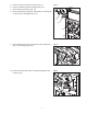
5. Remove transfer case with two latches (Fig. 4.1). Fig. 4 6. Remove ice deflection plate by lifting up (Fig. 4.2). 7. Remove auger by lifting up (Fig. 4.3). 8. Remove auger tube by lifting up. Note position of locating slot on lower end for reinstallation (Fig. 4.4). 1 2 3 4 9. Remove blower duct by loosening thumb screw, rotating clip (Fig. 5.1) and lifting up (Fig. 5.2). Fig. 5 2 1 10. Remove control box/fan motor mounting assembly with two screws (Fig. 6). 7 Fig.
11. Remove auger motor bracket with 8 screws (Fig 7). Fig. 7 12. Remove bag pin bracket with two thumbscrews (Fig. 7). 13. The unit's width may be further reduced by removing the upper ice storage section (Fig. 8). This reduces unit width by 1.75" (45mm) to an overall width of 34" (864mm). Fig. 8 a) Remove window. b) Pull window interlock switch cable through wire trough in upper right corner of base (Fig. 8.1). c) Cut tie wrap. d) Release latch from each side of ice storage section (Fig. 8.2).
Locating unit Fig. 9 A minimum of 12" (305mm) to the left of the unit must be unobstructed for service clearance (see dimensions and clearances). 1 Leg extension accessory 1. Raise unit off feet. 2. Remove each standard foot channel with four carriage bolts (Fig. 9.1). 1 1 2 2 2 3. Remove foot insert and cap insert from standard foot channel. 4. Align each accessory extension foot channel to the eight holes of leg. 4.
Bag wicket Fig. 11 Note: Bags must be placed behind rear stainless chute. 1. Move chute lever to down position (Fig. 11.1). 2. Transfer bags from wicket to bag pins by removing cardboard backing and sliding 15 to 20 bags onto pins at a time until posts are full (Fig. 11.2). 1 3. Return chute lever to up position (Fig. 12). 2 Sanitize Follow cleaning and sanitizing instructions. Icemaker Follow icemaker manufacturer’s recommendations for installation. Fig.
Review operation procedures with appropriate operations person. Give manual to appropriate operations person. Cleaning and sanitizing Fig. 14 Solution A – Cleaning solution: Combine 1 oz (30ml) bleach with 2 gal (8L) hot water or use an equivalent sanitizer and mix for 200 ppm. 1 Solution B – Sanitizing solution: Combine 1/4 oz (7ml) bleach with 2 gal (8L) hot water or use an equivalent sanitizer and mix for 50 ppm.
Operation How the dispenser works Follett’s Ice Pro bagging and dispensing system is available in manual or semi-automatic ice dispensing and bagging configurations. The semi-automatic model includes a blower to puff bags open for high volume, handsfree dispensing, bag holder pins for use with wicketed bags and programmable dispense timer. Ice is stored above a dispense auger in the dispenser storage area. An automatic agitation cycle keeps the ice from congealing by periodically activating the agitator.
Control functions Model DB1000SA – Semi-automatic ice bagging and dispensing system controls 1. Open bag Press to turn on blower. Automatically blows open one bag at a time Press again to turn blower off. Blower automatically turns off after 10 minutes. 1. Open bag 2. Adjust time Press +/– to change timed dispense duration in seconds - maximum time: 30 seconds 3. Dispense ice 2. Adjust time Press Timed once to dispense automatically. Hold Manual to top off bag or fill other containers 3.
Bag pin – installing wickets (Model DB1000SA only) Fig. 16 Note: Bags must be placed behind rear stainless chute. 1. Move chute lever to down position (Fig. 16.1). 2. Transfer bags from wicket to bag pins by removing cardboard backing and sliding 15 to 20 bags onto pins at a time until posts are full (Fig. 16.2). 1 3. Return chute lever to up position (Fig. 17). 2 Adjusting bag stand height (Model DB1000SA only) The bag stand platform may be raised or lowered to accommodate multiple bag sizes (Fig.
Service Fig. 20 Agitator removal 1 1. Remove all ice from dispenser. 2. Disconnect power to dispenser and icemaker. 3. Remove window from upper ice storage section. 2 4. Remove connection pin from left side of agitator bar (Fig. 20). 5. Move agitator bar toward left dispenser wall (Fig. 21.1) while pulling out the right side from bearing (Fig. 21.2). 6. Push right side of agitator bar toward rear right corner of bin (Fig. 22.1) while pulling out the left side from the drive shaft (Fig. 22.2). 7.
Wiring diagram DB1000 - ICE PRO SCHEMATIC DB1000SA - ICE PRO SCHEMATIC OPERATOR INTERFACE PB5 TIMED MODE INCREASE PB6 BAG OPEN START/STOP PB3 TIMED MODE START/STOP 6.
Before calling for service 1. 2. 3. 4. Check that ice is in the dispenser and that congealed cubes are not causing a jam. Check that circuit breaker and switches are in ON position. Check that window is on securely. If ajar, dispenser will not operate. Check that all drains are clear. Troubleshooting guide Symptom Ice does not dispense Bags tear off pins during filling Possible cause Solution 1. No ice in bin 1. Check operation of ice maker 2. Dispense switch not closing 2.
Replacement parts 2 19 16 5 18 16 1 8 15 17 9 15 21 13 14 12 21 14 7 4 10 3 21 22 3 6 11 Reference # Description 20 Part # 1 Panel, access, side 00109751 2 Latch, hopper 00109769 3 Tensioner (includes 00109868) 00109777 4 Bearing (includes 00109876) 00109785 5 Sprocket, agitator (includes 00101048) 00109793 6 Sprocket, drive 00109801 7 Sprocket, idler (includes 00109884) 00109819 8 Frame, outer bearing support (includes (2) 00109785, (2) 00109876) 00109827 9 Ha
21 11 24 1 17 14 20 15 18 16 25 7 9 10 12 26 8 23 22 23 2 5 15 6 5 13 3 4 5 19 Reference # Description Part # 1 Hood, dispense 00109918 2 Cover, dispense (includes 00111039) 00109926 3 Bag stand (includes (2) 00104299) 00109934 4 Drain pan 00925503 5 Handle, insert 00104299 6 Panel, access, front (includes 00104299) 00109959 7 Chute, outer, dispense 00109967 8 Bracket, bag hanger (includes (2) 208626, (2) 208940, (2) 500915) 00109975 9 Chute, inner, dispense 00
15 24 20 16 8 14 2 1 18 12 21 22 2 11 19 23 23 17 19 5 10 6 4 7 9 8 3 1 Reference # Description Part # 1 Tube, auger 00100958 2 Auger 208816 3 Deflector, ice 00110106 4 Plate, lower, auger drive 00110114 5 Plate, cover, auger drive 00110122 6 Chain, auger drive 208935 7 Latch, auger drive 00110148 8 Coupling, auger motor 00110155 9 Transmission, auger drive (includes 00110114, 00110122, 00110130, 00110155, 00110171) 00110163 10 Tensioner, auger chain 00110171
3 9 2 1 5 6 8 7 4 Reference # Description Part # 1 Bearing, agitator support 00110254 2 Kit, shaft seal, agitator (includes 00110338) 00110312 3 Gasket, tube seal, auger 00102061 4 Kit, tube seal, auger (includes 00102061, 00110346) 00110320 5 Base, seal 00101246 6 Seal, agitator 00103911 7 Collar, seal 00101535 8 Hardware, mounting, shaft seal (set of 4) 00110338 9 Hardware, mounting, tube seal (set of 6) 00110346 21
2 5 1 3 Reference # Description 4 Part # 1 Inverter, auger 00925651 2 Inverter, agitator 00925651 3 Fuse holder 00105411 4 Fuse, 10 amp 208823 5 Switch, rocker 208867 22
DB1000-SA DB1000 2 3 3 5 1 1 2 5 4 Reference # Description 4 Part # DB1000–SA 1 Control board (Serial # above D51557) 00924597 1 Control board, green display (before Serial # D51558) 00104521 Control board (red display) – obsolete. Use retrofit kit 00129833 below.
801 Church Lane • Easton, PA 18040, USA Toll free (877) 612-5086 • +1 (610) 252-7301 www.follettice.