25 and 50 Series - 220 V 60 Hz/230 V 50 Hz Ice and Water Dispensers Installation, Operation and Service Manual Order parts online www.follettice.com C/E25CT400A/W-S C/E25CR400A/W-S C/E50CR400A/W-S C/E50CT400A/W-S C/E25HR400A/W-S C/E25HT400A/W-S C/E50HR400A/W-S C/E50HT400A/W-S C/E25FB400A/W-S C/E50FB400A/W-S Following installation, please forward this manual to the appropriate operations person. 801 Church Lane • Easton, PA 18040, USA Toll free (877) 612-5086 • +1 (610) 252-7301 www.follettice.
25/50 Series 220 V 60 Hz/230 V 50 Hz Dispensers
Table of contents Before you begin Specifications Field wiring Installation Installing freestanding dispensers Installing countertop dispensers Installing wall mount dispensers Installing ice machines with RIDE® remote ice delivery equipment Installing top mount ice machines User information Cleaning and sanitizing procedures Service Information Wiring diagram – models with lever dispensing Wiring diagram – models with SensorSAFE™ infrared dispensing Dispenser troubleshooting Troubleshooting SensorSAFE boar
Welcome to Follett Follett equipment enjoys a well-deserved reputation for excellent performance, long-term reliability and outstanding after-the-sale support. To ensure that this equipment delivers that same degree of service, we ask that you review the installation portion of this manual before beginning to install the unit. Our instructions are designed to help you achieve a trouble-free installation.
Specifications Electrical 1. Models with RIDE ice machines (C/E25CR400A/W, C/E50CR400A/W, C/E25HR400A/W, C/E50HR400A/W) Basic electrical: 220 V 60 Hz/230 V 50 Hz 2. Ice machine Dispenser 5A 1.5A Freestanding models and models with integral ice machines (C/E25FB400A/W, C/E50FB400A/W, C/E25CT400A/W, C/E50CT400A/W, C/E25HT400A/W, C/E50HT400A/W) Total system Basic electrical: 220 V 60 Hz/230 V 50 Hz 3. 6.5A Dispensers and RIDE ice machines are supplied with a 2m (7ft) power cord.
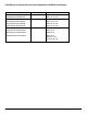
Field Wiring: countertop and wall mount dispensers with RIDE ice machines Model Electrical connection Current C25FB400A/W, C50FB400A/W cord provided 220 V 60 Hz, 6.5A E25FB400A/W, E50FB400A/W C25CT400A/W, C50CT400A/W 230 V 50 Hz, 6.5A cord provided 220 V 60 Hz, 6.5A E25CT400A/W, E50CT400A/W 230 V 50 Hz, 6.5A C25HT400A/W, C50HT400A/W 220 V 60 Hz, 6.5A E25HT400A/W, E50HT400A/W 230 V 50 Hz, 6.
Installation procedures Before you begin • All dispensers must be installed level in both directions to ensure proper operation • Required ventilation and recommended service clearances: • Countertop and wall mount models with RIDE ice machine (C/E25CR400A/W, C/E25HR400A/W, C/E50CR400A/W, C/E50HR400A/W) — none. 305mm (12") at top recommended for service • Countertop and wall mount models with integral ice machine (C/E25CT400A/W, C/E25HT400A/W, C/E50CT400A/W, C/E50HT400A/W) — 153mm (6") at top.
Fig. 1 – Rear connections, freestanding models access panel (19mm) 3/4" FPT drain (B) power cord 20mm (.8") (A) 10mm (3/8") push-in water inlet 267mm (10.5") 10mm (3/8") FPT condenser inlet location (D) (water-cooled only) 10mm (3/8") FPT condenser outlet location (E) (water-cooled only) 19mm (3/4") MPT icemaker drain location (C) (water-cooled only) 171mm (6.75") 800mm (31.5") 384mm (15.125") 259mm (10.25") 79mm (3.125") 79mm (3.
Installing countertop dispensers 1. Position dispenser in desired location, mark dispenser outline on counter and remove dispenser. Dispensers with top mount ice machines cannot be mounted on legs. They must be bolted to counter. Use gloves when lifting ice machine to protect hands from sheet metal edges. ! 2. Drill four 10mm (3/8") holes in counter (Fig. 2) to anchor dispenser to counter.
6. Temporarily remove rear access panel (Figs. 4, 5) from rear of dispenser. Fig. 4 – Rear connections, countertop models with integral ice machines 7. Loosen junction box mounting screws. Lift junction box and power cord up until cord and mounting screws clear notches on rear panel of dispenser. Remove Phillips head screws from right side of junction box. 8. Rotate junction box 90 degrees so that screw holes on right side of junction box align with holes on rear dispenser panel.
Installing wall mount dispensers 1. Install supplied wall bracket with six 10 mm (3/8") diameter fasteners as shown in Fig. 7. Note: Three holes are available at each fastening site to allow capture of studs/support within wall. Steps 2 - 3 are required for models with integral ice machine only (C/E25HT400A/W and C/E50HT400A/W). 2. For models with integral ice machine, use straight edge to position filler strip flush with top edge of wall bracket. 3. Fasten filler strip to wall as shown in Fig. 8. 4.
8. Remove utility knock-out (Fig. 4, 5F) from rear of dispenser and install supplied protective grommet. For dispensers using RIDE ice machines, remove ice transport tube knock-out (Fig. 5G) from rear of dispenser. 9. Run water supply line from back through utility knock-out (Fig. 5F) and connect water supply line to 3/8" FPT fitting on utility flange at bottom of dispenser (Fig. 3G). 10. Connect and run a dedicated drain line from 3/4" drain tube to wall or floor drain. An air break should be provided. 11.
Installing RIDE ice machines (models C/E25CR400A/W, C/E50CR400A/W, C/E25HR400A/W, C/E50HR400A/W) ! See Ice machine Installation Manual (form #00124453) for critical installation instructions for remote ice machines. Failure to comply with these instructions will result in poor performance and void warranty. 1. Install RIDE ice machine following instructions in ice machine manual. 2. Run uninsulated ice transport tube from dispenser through ice transport tube knock-out (Fig.
Installing top mount ice machines (models C/E25CT400A/W, C/E50CT400A/W, C/E25HT400A/W, C/E50HT400A/W) ! Dispensers with top mount ice machines cannot be mounted on legs. They must be bolted to counter. Use gloves when lifting ice machine to protect hands from sheet metal edges. 1. On dispensers equipped with top mounted, water-cooled ice machines, feed condenser supply and drain lines from back through utility knock-out (Fig. 4F) or through counter, as appropriate.
Fig. 11 – Ice transport tube and bin thermostat capillary tube mounting units with top mounted ice machines capillary tube 19mm (.75") Hand bend cap tube end to approx.
User information How the dispenser works Follett’s 25 and 50 automatic load ice and water dispensers receive ice from Follett’s 181kg (400lb)/day ice machine located in the dispenser base, in the cabinet top or in a remote location up to 6m (20 ft) away. Ice produced is stored in the bin section of the dispenser. When the dispense lever is pushed, the wheel motor is energized, causing the wheel to turn. This moves ice to the dispense chute where it drops by gravity into the container held below the chute.
Recommended cleaning/descaling and sanitizing intervals* Symphony Frequency Drain Line weekly Drain Pan/Drip Pan weekly Exterior Condenser * as needed monthly (air-cooled only) Dispenser and Components semi-annually Ice Machine semi-annually Chilled Water Accessory semi-annually Transport Tube semi-annually Ice Storage Area/Bin semi-annually Ice machine and dispenser must be cleaned and sanitized prior to start-up.
CAUTION! § § § § Wear rubber gloves and safety goggles (or face shield) when handling cleaner or sanitizer mixtures. Use only Follett approved cleaners. It is a violation of Federal law to use Solution A or Solution B in a manner inconsistent with their labeling. Do not use solvents, abrasive cleaners, metal scrapers or sharp objects to clean any part of the dispenser. Solution A: Following manufacturer’s instructions, mix cleaning solution of 1 gal. (3.8 L) 120 F (49 C) water and 7 oz. (198 g) (one 7 oz.
Service information Wiring diagrams How unit works — lever models The dispense wheel motor is energized through the power and ice dispense switches. The water solenoid valve is energized through the power and water dispense switches. The ice machine receives the bin signal through the normally closed bin thermostat and the bin signal switch. When the bin level thermostat is calling for ice, a 16V circuit is completed to the bin signal terminals on the ice machine circuit board.
How unit works — SensorSAFE models SensorSAFE models provide “touchless” ice and water dispensing. When a container is placed within the actuation zone below the ice or water chute on SensorSAFE dispenser models, an infrared signal reflects off the container and is detected by the sensor. The sensor then sends a signal to the control board to activate the appropriate components to dispense ice or water. LEDs on the board indicate when the board is receiving a signal from the sensors.
Dispenser troubleshooting Before calling for service: ! Disconnect power to dispenser and ice machine before putting hands or arms in storage area, or attempting any repair or service to equipment. • Check that there is ice in dispenser bin area • Check that all switches and circuit breakers are on • Check that congealed cubes are not causing a jam • Check that all drains are clear Symptom 1. Does not dispense ice. a. b. c. d. e. Possible cause Power switch off or faulty. Faulty dispense switch.
Troubleshooting SensorSAFE board and sensors Board guide LEDs, when illuminated, indicate the following: Terminals: L1 (incoming power, hot) L2 (neutral terminals) WTR (power terminal for water solenoid) SOL (power terminal for dispense gate solenoid) not used WM (power terminal for wheel motor) CLN (terminals for clean cycle switch) PWR (board power) CLN (cleaning, no dispensing cycle) ICE (ice dispensing activated) WTR (water dispensing activated) Problem: Does not dispense ice or water Action PWR Ch
Lens/sensor troubleshooting 1. Turn dispenser power switch off. 2. Remove splash panel. 3. Disconnect wires from output terminal(s) (WTR, WM) on board. 4. Gently remove appropriate sensor/mounting block assembly from panel by moving block sideways until edge of block clears retaining tab of panel. 5. Inspect lens and sensor assembly for foreign material and remove using non-abrasive cleaner. 6.
Disassembly and replacement instructions Dispense chute removal 1. Remove dispenser front cover. 2. Slide plastic dispense chute cover up and out to remove. 3. Pull out four white plastic fasteners and remove dispense chute. Dispense wheel removal and installation Note: Models with top mount ice machines require removal of ice machine before removing wheel. 1. Remove all ice from storage area of dispenser. 2. Remove center thumbnut from dispense wheel. 3.
Ice transport tube replacement models C/E25FB400A/W, C/E50FB400A/W, C/E25CR400A/W, C/E50CR400A/W ! Correct installation of ice transport tube is critical to RIDE ice machine performance. Replacement ice transport tubes for remote ice machines must be insulated and run continuously from ice machine to dispenser with no dips or bends with a radius of less than 153mm (6"). 1. Remove top and rear access panel from dispenser (lower front panel in freestanding unit). 2.
Thermostat locations Thermostat locations – C/E25CT400A/W, C/E25HT400A/W, C/E50CT400A/W, C/E50HT400A/W ice deflector bracket assembly rubber grommet capillary tube capillary tube bin thermostat control box assembly hopper assembly control box assembly capillary tube 19mm (.75") Hand bend cap tube end to approx.
Replacement parts Dispenser exterior 7 6 2 2 4 9 3 1 5 Part # 502916 502917 502918 502919 502694 502681 501100 502682 502683 502688 502684 502699 502088 502298 502920 502685 00112854 502924 502923 502921 502268 502700 502922 502778 502701 00109728 502359 502816 502817 502945 502931 502930 502805 502925 10 8 Description Reference Cover, top front, 25 countertop (CT) & wall mount (HT) units 1 Cover, top front, 50 countertop (CT) & wall mount (HT) units 1 Cover, top front, 25 countertop units with RIDE i
Dispense chute and splash panel areas (lever models) — Serial Number E08194 and above 4 15 2 12 6 1 8 10 13 5 3 9 7 11 14 Reference Description Part # 1 Fastener, 10-32 x 3/8" stainless steel 00982421 2 Tube, water station 502356 3 Cover, dispense chute 502681 4 Switch, dispense, lever actuated (includes 501841) 502359 5 Bracket, lever and water solenoid 01039635 6 Bracket, lever 00958793 7 Lever, dispense 00976845 Agion® antimicrobial product protection1) 01041201 8 C
Dispense chute and splash panel areas (lever models) — Serial Numbers below E08193 7 4 13 2 10 8 14 12 11 1 6 5 15 9 3 16 Reference Description Part # 1 Fastener, dispense chute bracket 502057 2 Tube, water station 502356 3 Cover, dispense chute 502681 4 Switch, dispense, ice, lever actuated (includes 501841) 502359 5 Switch, dispense, water, lever actuated (includes 501841) 502359 6 Bracket, chute (includes fasteners 502057) 502247 7 Lever, dispense 502358 8 Chute and fu
Dispense chute and splash panel areas (SensorSAFE) — Serial Number E08194 and above 8 5 7 9 10 2 6 1 11 12 13 3 4 Reference Description Part # 1 Cover, dispense chute 502681 2 Chute, ice (with Agion® antimicrobial product protection1) 01041201 3 Chute, water (with Agion) 01042266 Not shown Chute, ice (with Agion® antimicrobial product protection1), wall hung 01040005 Not shown Chute, water (with Agion), wall hung 00984898 4 Lens, sensor 502690 5 Splash panel, SensorSAFE dispen
Dispense chute and splash panel areas (SensorSAFE) — Serial Numbers below E08193 10 12 8 15 3 13 11 9 1 14 7 2 5 4 6 Reference Description Part # 1 Fastener, dispense chute bracket 502057 2 Cover, dispense chute (includes labels) 502681 3 Chute and funnel, ice 502689 4 Chute, water 502249 5 Bracket, chute (includes fasteners 502057) 502247 6 Lens, sensor 502690 7 Splash panel, units with drain pan (includes 2 of 502690) 502695 Not shown Splash panel, wall mount units w/o d
Electrical box (front view) – SensorSAFE models 1 3 2 2 Reference Description Part # 1 Thermostat, bin level 500514 2 Switch, dispenser power 502209 2 Switch, ice machine bin signal 502209 3 Control board, SensorSAFE 220V 60Hz/230V 50Hz 502915 Not shown Clean switch, SensorSAFE 502359 Not shown Boot, clean switch 501841 Wheel motor and drive system 3 8 7 5 4 3 2 6 7 1 1 Reference Description Part # 1 Wheel motor, 220 V 60 Hz/230 V 50 Hz 501699 2 Washer, thrust 501026
Hopper components Top view – freestanding and RIDE units Top View – All top mounted units 6 16 13 2 15 1 17 12 14 4 8 1 2 7 Ice tube bracket, side view all top mounted units Ice tube bracket, side view, freestanding & RIDE units 5 9 10 8 4 Reference Description Part # 1 Baffle, ice 501608 2 Wheel, dispense (includes 501612) 502821 4 Bracket, ice tube 502712 6 Rod, threaded (includes knurled nut) 501612 8 Ice deflector/cap tube bracket (units with top mounted ice machine) 5016
Ice transport tubing Reference Description Part # Not shown Ice transport tube (RIDE units) 3m (10 ft) 502522 Not shown Ice transport tube (Satellite-fill units) 6m (20 ft) 502523 Not shown Ice transport tube insulation (RIDE units only) - sold by the foot 501176 Not shown Ice transport tube assembly (50 freestanding (FB) units) 502328 Not shown Ice transport tube assembly (25 freestanding (FB) units) 502329 Not shown Ice transport tube assembly (top mount units) 502697 Chilled water co
25/50 Series 220 V 60 Hz/230 V 50 Hz Dispensers 35
SensorSAFE and Symphony are trademarks of Follett Corporation. Follett and RIDE are registered trademarks of Follett Corporation, registered in the US. 801 Church Lane • Easton, PA 18040, USA Toll free (877) 612-5086 • +1 (610) 252-7301 www.follettice.