10 Series – 220V 60Hz/230V 50Hz Ice and Water Dispensers Order parts online www.follettice.com Installation, Operation and Service Manual C/E110CT400A/W C/E110CR400A/W C/E110FB400A/W Following installation, please forward this manual to the appropriate operations person. 801 Church Lane • Easton, PA 18040, USA (610) 252-7301 • Fax (610) 250-0696 • www.follettice.
Table of contents Before you begin Specifications Field wiring Installation Installing freestanding dispensers Installing countertop dispensers Installing Satellite-fill™ icemakers Installing top mount icemakers User information Cleaning and sanitizing procedures Service Information Wiring diagram – lever models Wiring diagram – SensorSAFE™ models Dispenser troubleshooting Troubleshooting SensorSAFE board and sensors Disassembly and replacement instructions Thermostat locations Parts Dispenser exterior Disp
Welcome to Follett Follett equipment enjoys a well-deserved reputation for excellent performance, long-term reliability and outstanding after-the-sale support. To ensure that this equipment delivers that same degree of service, we ask that you review the installation portion of this manual before beginning to install the unit. Our installation instructions are designed to help you achieve a trouble-free installation.
Specifications Electrical 1. Models with Satellite-fill icemakers (C/E110CR400A/W) Icemaker 5 amps 5 amps 220V/60Hz/1 phase 230V/50Hz/1 phase 2. Freestanding models and models with integral icemakers (C/E110FB400A/W, C/E110CT400A/W) Total system 6.5 amps 6.5 amps 220V/60Hz/1 phase 230V/50Hz/1 phase 3. Dispenser 1.5 amps 1.5 amps Dispensers and Satellite-fill icemakers are supplied with 7-foot power cord Ambient Air temp Water temp Water pressure 38°C/100° F max. 32°C/90°F max. 70 P.S.I. max.
Field wiring for countertop dispensers with Satellite-fill icemakers Model Electrical connection Current C110FB400A/W cord provided 220V 60Hz, 6.5 amp E110FB400A/W C110CT400A/W 230V 50Hz, 6.5 amp cord provided E110CT400A/W C110CR400A/W E110CR400A/W 220V 60Hz, 6.5 amp 230V 50Hz, 6.5 amp cord provided 220V 60Hz 230V 50Hz dispenser: 1.5 amp icemaker: 5.
Installation procedures Before you begin • All dispensers must be installed level in both directions to ensure proper operation • Required ventilation and recommended service clearances: • Countertop models with Satellite-fill icemaker (C/E110CR400A/W) — none. 305mm (12") at top recommended for service. • Countertop models with integral icemaker (C/E110CT400A/W) — 153mm (6") at top. 153mm (6") each side recommended for service. • Freestanding models (C/E110FB400A/W) — 102mm (4") at rear.
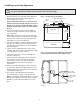
Fig. 1 – Rear connections, freestanding models access panel (B) 3/4” FPT drain (A) 3/8" FPT water inlet (A) 800mm (31.5") (D) 3/8" FPT condenser inlet location (watercooled only) water inlet (C) 3/4" MPT icemaker drain location (watercooled only) (E) 3/8" FPT condenser drain location (watercooled only) 800mm (31.5") (C) 3/4" MPT icemaker drain location (aircooled only) 260mm (10.25") 12. Verify that water sensor tabs are immersed in water in reservoir. 13.
Installing countertop dispensers ! Dispensers with top mount icemakers cannot be mounted on legs. They must be bolted to counter. Use gloves when lifting icemaker to protect hands from sheet metal edges. 1. Position dispenser in desired location, mark dispenser outline on counter and remove dispenser. Fig. 2 – Counter cut-out, all models 2. Drill four 5mm (3/8") holes in counter (Fig. 2) to anchor dispenser to counter. 227mm x 356mm (9" X 14") 622mm (24.
10. Apply a thick bead, approximately. 6mm (1/4") diameter, of NSF listed silicone sealant (DowCorning RTV-732 or equivalent) 6mm (1/4") inside marked outline of dispenser. Fig. 4 – Rear connections, countertop models with integral icemakers (M) 3/8" FPT icemaker water inlet 11. Carefully position dispenser on counter. 12. Remove four screws securing splash panel to front of dispenser and gently lay splash panel on counter.
Installing Satellite-fill icemakers Models C/E110CR400A/W ! See Icemaker Installation Manual (form #00124453) for critical installation instructions for Satellitefill icemakers. Failure to comply with these instructions will result in poor performance and void warranty. 1. Install Satellite-fill icemaker following instructions in icemaker manual. 2. Run uninsulated ice transport tube from dispenser through ice transport tube knock-out, (Fig. 5G) or through counter opening to icemaker. 3.
1. Remove dispenser top front cover by removing two screws at bottom corners of cover, lifting cover slightly and pulling forward. 2. Remove icemaker compartment top and side panels. 3. Remove icemaker hold-down bracket from front of icemaker compartment. 4. Lift icemaker onto dispenser top and slide icemaker completely into position, compressor end first. Front of icemaker base must be flush with front of dispenser. 5.
User information How the dispenser works Follett’s 110 series automatic load ice and water dispensers receive ice from Follett’s 181kg (400 lb)/day icemaker located in the dispenser base, in the cabinet top or in a remote location up to 6m (20 ft) away. Ice produced is stored in the bin section of the dispenser. When dispensing is activated, the wheel motor is energized, causing the wheel to turn. This moves ice to the dispense chute where it drops by gravity into the container held below the chute.
Recommended weekly cleaning 1. Wash drain pan and grille with Solution A above. Rinse thoroughly. 2. Slowly pour solution of one cup (237ml/8 oz) household bleach mixed with 3.8L (1 gallon) hot water into drain pan to help prevent algae growth in drain lines. If dispenser is a SensorSAFE unit: 3. Deactivate dispenser by depressing and releasing clean switch located on left side of unit under top front cover. 4. Clean lens using soft cloth and mild, non-abrasive cleaner. 5.
Service information Wiring diagrams How unit works — lever models The dispense wheel motor and dispense solenoid are energized through the power and ice dispense switches. The water solenoid valve is energized through the power and water dispense switches. The icemaker receives the bin signal through the power switch, the normally closed bin thermostat and the icemaker switch.
How unit works — SensorSAFE models SensorSAFE models provide “touchless” ice and water dispensing. When a container is placed within the actuation zone below the ice or water chute on SensorSAFE dispenser models, an infra-red signal reflects off the container and is detected by the sensor. The sensor then sends a signal to the control board to activate the appropriate components to dispense ice or water. LEDs on the board indicate when the board is receiving a signal from the sensors.
Dispenser troubleshooting ! Disconnect power to dispenser and icemaker before putting hands or arms in storage area, or attempting any repair or service to equipment. Before calling for service: • Check that there is ice in dispenser bin area • Check that all switches and circuit breakers are on • Check that congealed cubes are not causing a jam • Check that all drains are clear Symptom 1. Does not dispense ice a. b. c. d. e. f. g.
Troubleshooting SensorSAFE board and sensors Board guide LEDs, when illuminated, indicate the following: PWR CLN ICE WTR Terminals: (board power) (cleaning, no dispensing cycle) (ice dispensing activated) (water dispensing activated) L1 L2 WTR SOL WM CLN (incoming power, hot) (neutral terminals) (power terminal for water solenoid) (power terminal for dispense gate solenoid) not used (power terminal for wheel motor) (terminals for clean cycle switch) Problem: Does not dispense ice or water Action PWR Ch
Lens/sensor troubleshooting 1. Turn dispenser power switch off. 2. Remove splash panel. 3. Disconnect wires from output terminal(s) (WTR, SOL, WM) on board. 4. Gently remove appropriate sensor/mounting block assembly from panel by moving block sideways until edge of block clears retaining tab of panel. 5. Inspect lens and sensor assembly for foreign material and remove using non-abrasive cleaner. 6. Turn dispenser power on and test sensor by moving hands through activation area (no closer than1.
Ice transport tube replacement Top mount ice machines, model C/E110CT400A/W ! Only use tubing supplied by Follett Corporation. 3 2 1 TIGHTEN CLAMP SCREW 4 Ice transport tube replacement Models C/E110FB400A/W, C/E110CR400A/W ! Correct installation of ice transport tube is critical to Satellite-fill icemaker performance.
All units 9. Slip supplied hose clamp onto tube and push tube onto exit port of evaporator. Do not twist hose when securing to evaporator. ! Only use tubing supplied by Follett Corporation. 10. Fasten tube on port with hose clamp, being sure that clamp is positioned on evaporator side of nozzle flange. 11. Tighten clamp.
Thermostat locations Thermostat locations – C/E110CT400A/W ice deflector bracket assembly rubber grommet ice level control stat ice level control stat bin thermostat control box assembly hopper assembly control box assembly ice level control stat .75" (20mm) Hand bend cap tube end to approx.
Parts Dispenser exterior 7 6 2 2 4 5 5 1 9 3 5 Part # 502756 502703 502704 502681 501100 502705 502706 502779 502709 502702 502088 502298 500376 502711 00112854 502100 502433 502222 502268 502716 502225 502701 00109728 502776 502777 502816 502817 502359 502788 502786 502805 8 Description Cover, top front, 110 countertop (CT) Cover, top front, 110 countertop unit with Satellite-fill icemaker (CR) & freestanding (FB) Cover, lower section, 110 freestanding (FB) units Cover, dispense chute Knurled screw
Dispense chute and splash panel areas — lever models 7 2 13 4 10 8 14 12 11 1 6 5 3 Part # 502057 502356 502681 501829 502359 502247 502358 502248 502249 502927 502355 502246 502262 502926 501841 502079 502789 9 16 Description Fastener, dispense chute bracket Tube, water station Cover, dispense chute Switch, dispense, ice, lever actuated (includes 501841) Switch, dispense, water, lever actuated (includes 501841) Bracket, chute (includes fasteners 502057) Lever, dispense Chute and funnel, ice Chute
Dispense chute and splash panel areas – SensorSAFE™ models 10 12 8 3 15 13 11 9 1 14 7 2 Part # 502057 502681 502248 502249 502247 502690 502710 502927 502355 502356 502246 502262 502926 00122978 203611 5 4 6 Description Fastener, dispense chute bracket Cover, dispense chute (includes labels) Chute and funnel, ice Chute, water Bracket, chute (includes fasteners 502057) Lens, sensor Splash panel (includes 2 of 502690) Solenoid assy, water, 220V, 60Hz/230V, 50Hz (incl.
Wheel motor and drive system 3 8 7 5 4 3 2 6 7 1 1 Part # 501699 501026 501607 501619 502691 502692 501019 501024 500799 500637 502929 Description Wheel motor, 220V, 60Hz/230V, 50Hz Washer, thrust Fan blade, wheel motor Drive shaft (includes threaded rod and nut, see #6, page 26) Chain, 54 link Sprocket, drive shaft, 35 teeth Sprocket, wheel motor, 10 teeth Bearing, drive shaft Connecting link, chain Key, driveshaft Dispenser drive assembly 25 Reference 1 2 Not shown 3 4 5 6 7 Not shown 8 Include
Hopper components Top view – freestanding and Satellite-fill units Top view – top mounted unit 17 6 16 13 2 15 5 4.
Ice transport tubing Part # 502522 502523 501176 502327 502697 Description Ice transport tube (Satellite-fill units) – 3.1m (10 ft) Ice transport tube (Satellite-fill units) – 6.
Solenoid dispense assembly 1 2 3 4 5 6 8 Part # 501844 502040 502039 502042 502054 502045 502038 501824 00128157 7 Description Solenoid, dispense, 220V, 60 Hz/230V, 50Hz Cotter pin Linkage, solenoid (includes 502054 grommet) Block, dispense gate Grommet Splash pan, gate assembly Shoulder screw and washer Spring, gate assembly Gate assembly, 220V, 60 Hz/230V, 50Hz (includes reference numbers 1 through 8 above) 801 Church Lane • Easton, PA 18040, USA (610) 252-7301 • Fax (610) 250-0696 • www.