Symphony Plus™ 12 Series Ice and Water Dispensers 12CI425A, 12HI425A Installation, Operation and Service Manual After serial number K39863 Please visit https://www.follettice.com/technicaldocuments for the Operation and Service manual for your unit. Welcome to Follett Follett equipment enjoys a well-deserved reputation for excellent performance, long-term reliability and outstanding after-the-sale support.
Contents Welcome to Follett. . . . . . . . . . . . . . . . . . . . . . . . . . . . . . . . . . . . . . . . . . . . . . . . . . . . . . . . . . . . . . . . . . . . . . . . . . . 3 Before you begin. . . . . . . . . . . . . . . . . . . . . . . . . . . . . . . . . . . . . . . . . . . . . . . . . . . . . . . . . . . . . . . . . . . . . . . . . . . 3 Specifications . . . . . . . . . . . . . . . . . . . . . . . . . . . . . . . . . . . . . . . . . . . . . . . . . . . . . . . . . . . . . . . . . . . . . . . . . . .
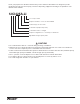
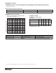
Check your paperwork to determine which model you have. Follett model numbers are designed to provide information about the type and capacity of Follett ice dispensing equipment. Following is an explanation of the different model numbers.
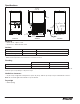
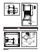
Specifications 22.625" (57.5 cm) air exhaust 32.00" (82.6 cm) 3/4" MPT drain air intake 16.00" (40.7 cm) 4.00" (10.2 cm) 23.5" (59.7 cm) Front View 18.00" (45.8 cm) Side View 3/8" FPT water inlet power cord (NEMA 5-15) Rear View Electrical § 115 V, 60 Hz, 1 phase, 11.0A § Connect to a 15A dedicated circuit. Ambient Air temp* 100 F/38 C Max. 50 F/10 C Min. Best performance below 80 F (27 C) Water temp 90 F/32 C Max. 45 F/4 C Min.
Refrigeration system Important: All service on refrigeration system must be performed in accordance with all federal, state and local laws that pertain to the use of refrigerants. It is the responsibility of the technician to ensure that these requirements are met. R425 ice machine charge specifications Model 12CI425A, 12HI425A (air-cooled) Charge Refrigerant type 15 oz R404A Refrigeration pressure data Air-cooled ice machine capacity/24 hrs.
Installation Before you begin § All dispensers must be installed level in both directions to ensure proper operation. § Service and ventilation clearances: 6" (15.3 cm) on right side of dispenser, 6" (15.3 cm) at top for ventilation and 12" (30.5 cm) at top recommended for service. § Countertop units installed without legs provide the option of taking utilities out bottom or back of dispenser (on wall mount units and countertop units with legs, utilities exit from back).
Installing countertop dispensers with legs accessory (P/N AF10LBLEGS) CAUTION! § Do not tilt unit further than 30° off vertical plane. § Countertop dispensers that sit on legs (not bolted to counter) can be inadvertently moved. Care should be taken when operating and cleaning to avoid accidents. 1. Carefully tip dispenser back to expose underside and block up in place. 2.
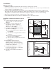
Installing wall mount dispensers CAUTION! § WALL PREPARATION: Wall and fasteners must be of sufficient strength to carry weight of unit (185 lb (83.9 kg). Hardware for this is not included. Notes: § SensorSAFE™ infrared dispensing is standard. 1. Recommended minimum counter depth and mounting height (Fig. 6) ensures that ice will drop into sink. 2. See Fig. 6 for model dimensions. The dimensions include the 0.5" (13 mm) mounting bracket supplied with the unit. 3. Cut utility hole in wall as shown (Fig. 5).
Fig. 5 – Wall mount dimensions Fig. 6 – Wall mount side view FRONT VIEW WALL STUDS 23.70" (60.2 cm) 16.00" TYP. (40.6 cm) ANCHOR POINTS 0.438" (11 mm) CLEARANCE WALL MOUNT BRACKET 13.00" (33.0 cm) 15.08" (38.3 cm) 32.00" (81.3 cm) 13.50" (34.3 cm) 2.88" (7.3 cm) 2.88" (7.3 cm) 8.08" (20.5 cm) 1.08" (2.7 cm) WALL CUTOUT 18.51" (47.0 cm) 20.53" (52.2 cm) 30.00" (76.2 cm) MIN DISTANCE TO SINK FRONT SUGGESTED POWER CORD ROUTING CAUTION! § Do not rest dispenser weight on bottom of support bracket.
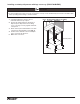
Fig. 9 – Wall mount, utility location FRONT VIEW water and drain tubing WALL MOUNT BRACKET WALL CUTOUT 1.41" (3.6 cm) 3.70" (9.4 cm) POTABLE WATER SUPPLY 3/8 COPPER TUBE 7.88" (20.0 cm) DRAIN 3/4 COPPER TUBE WALL 1.72" (4.4 cm) 0.92" (23 mm) 11.75" (29.9 cm) POWER CORD EXIT 3.00" (7.7 m) MAX. SIDE VIEW UTILITIES EXITING WALL User information How the dispenser works Follett’s 12 series automatic-load ice and water dispensers are equipped with Follett’s 425 lb (193 kg)/day ice machine.
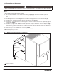
Panel removal Fig. 10 Fig. 11 Top cover: Lift cover up and off Velcro strips. Front cover: Pull bottom of cover, then lift cover up and forward to unhook from keyhole slots. Fig. 12 Fig. 13 Splash panel: Remove 4 screws. Pull out bottom of panel to allow top to slide out from under hopper support lip. Side panels: Remove screws. Lift panel to disengage from back panel, then remove. Note: Before removing right hand side, remove side louver panel by lifting up and pulling forward on panel.
Cleaning and sanitizing Follett ice machines and dispensers, and their associated cleaning and sanitizing procedures, are designed for use with potable water sources. The presence, or suspected presence, of infectious agents may call for additional measures, including the replacement of components and more comprehensive disinfection measures.
Weekly CAUTION! § Do not use solvents, abrasive cleaners, metal scrapers or sharp objects to clean any part of the dispenser. Dispenser drain pan and drain line § Pour 1 gal. (3.8 L) of hot tap water into drain pan to flush drains. Splash panel front, SensorSAFE infrared dispensing 1. Deactivate dispensing by pressing and releasing clean switch located on left side of unit under top front cover. 2. Clean lens and splash panel front using a soft cloth and mild, non-abrasive, non-chlorine based cleaner. 3.
Ice Machine and Dispenser Cleaning procedure Note: Check drains and drain cup to ensure they are open and flowing freely. 1. If ice machine was running recently, ensure that the evaporator is completely free of ice before proceeding. If there is ice in the evaporator, complete steps 2-7 using only hot water to remove the ice then begin Cleaning Procedure again. 2. Remove front cover and turn OFF bin signal switch. 3. Dispense all ice from storage hopper and discard. 4. Remove top of machine and hopper lid.
[OPTIONAL] Finish cleaning – No-rinse sanitizing with Nu-Calgon IMS-III 19. Press CLEAN switch. The MAINTENANCE light will turn on and the machine will drain. Wait for the LOW WATER light to turn on. 20. Remove lid from cleaning cup and fill (about 1 quart) until sanitizing solution overflows from the ice transport tube into the hopper. Place lid back on cup. Save remainder of sanitizing solution. 21.
Service Ice machine operation (all models) Follett’s ice machine consists of four distinct functional systems: § Harvesting system § Water system § Electrical control system § Refrigeration system These four systems work together to accomplish the production and harvesting of ice. A problem in any one of these systems will result in improper operation of the entire ice production cycle.
Water system The water level in the evaporator is controlled by a fill solenoid (Fig. 14) and level detecting sensors. Water sensing rods (Fig. 15) extend down into the reservoir at the end of the evaporator assembly. The system works via electrical conductivity as follows: One of the longest probes is a common. When water is between any of the other probes and the common, the PC board will sense the activation.
Access to electrical box and control board The 12 series electrical box has been designed to slide out for easy access to the control board and more convenient troubleshooting. 1. Remove top and front panels of dispenser (for panel removal instructions see page 12). 2. Remove electrical box cover. 3. Pull electrical box toward front of unit. Fig. 16 electrical box electrical cover Electrical system ATTENTION! To prevent circuit breaker overload, wait 15 minutes before restarting this unit.
Control board DIP switch settings OFF POSITION OFF 2 ON Sleep cycle dispense duration 5 4 6 7 5 5 8 7 4 5 5 4 6 15 s 5s 3 5 35 s 4 ON 4 OFF 2 4 8 Sleep cycle enabled Not used Sleep cycle dispense duration 60 min. time delay Flush enabled Maint. timer OFF 1 3 Maint. timer ON 1 Sleep cycle disabled Not used Sleep cycle dispense duration 20 min.
Wiring diagram POWER SWITCH L1 B BLACK #19 L2/N GND GND TO MAIN FRAME BLACK #23 BLACK #24 BLACK #25 GRN #27 WHITE #22 WHITE # WHITE #26 WHITE # LEVER ONLY NEUTRAL BLACK #39 WATER SENSOR ICE SENSOR 4 1 1 COMPONENTS MOUNTED ON SPLASH PANEL LEVER ONLY 4 4 BLACK #41 ICE STATION SWITCH COMPONENTS MOUNTED ON MAIN FRAME 1 2 3 4 M WHEELMOTOR COVER INTERLOCK SWITCH BLACK #61 WHITE #62 GREEN #63 WHITE #64 WATER DISPENSE SOLENOID WHITE #34 S SENSORSAFE ONLY 1 BLACK #31 BLACK #33 BLA
BLACK #19 WHITE #22 BLACK #23 BLACK #23 WHITE #26 BLACK #24 N N N N N N N N N ICE AUX WATER AUX P15 P16 BLACK #01 T1 L1 L1 BLACK #24 P2 COMPRESSOR BLACK #51 D3 D4 D5 K1 D16 L1 HI PRS P14 S1 P1 MODEL SELECT D19 BLACK #21 (SENSORSAFE) BLACK #25 (LEVER) D1 D2 D6 D7 D8 D22 P6 D37 K3 CURRENT SENS P17 WATER LEVELS D17 P3 6 5 PROGRAM D20 P19 2 1 D18 D21 P20 D9 P9 P21 S2 P10 SERIAL COMM P22 D48 P7 P4 P5 T2 AUGER D11 D12 RESET P13 P12 BIN P11 D10 RS48
Wiring diagram - Lever only POWER SWITCH BLACK #19 L1 L2/N GND BLACK #23 BLACK #24 BLACK #24 GRN #27 BLACK #25 BLACK #25 BLACK #23 WHITE #26 GND TO MAIN FRAME 4 4 12CI425A, 12HI425A ICE STATION SWITCH 1 4 BLACK #41 BLACK #33 S WHITE #34 WATER DISPENSE SOLENOID 22 COMPONENTS MOUNTED ON SPLASH PANEL LEVER ONLY BLACK #30 BLACK #31 BLACK #32 WATER STATION SWITCH 1 1 BLACK #29 BLACK #28 M COMPONENTS MOUNTED ON MAIN FRAME WHEELMOTOR COVER INTERLOCK SWITCH WHITE #26
Wiring diagram - SensorSAFE only POWER SWITCH BLACK #19 L1 L2/N GND WHITE #26 SENSORSAFE ONLY GRN #27 NEUTRAL BLACK #38 BLACK #39 BLACK #24 ICE BLACK #25 WTR BLACK #23 WHITE #26 GND PWR CLN 1 L1 SOL WM BLACK #24 WTR BLACK #25 BLACK #21 WHITE #22 GND TO MAIN FRAME WHITE #22 BLACK #23 WATER SENSOR ICE SENSOR GRN #20 4 CLEAN SWITCH COMPONENTS MOUNTED ON SPLASH PANEL WATER DISPENSE SOLENOID 1 4 S BLACK #41 BLACK #33 WHITE #34 BLACK #32 SENSORSAFE ONLY M COMPONENTS MOUNTE
Ice machine operational and diagnostic sequences The wiring diagrams that follow illustrate the circuitry of Follett ice machines used with 12 series ice dispensers. Both normal operation (stages 1–8) and non-normal diagnostic sequences showing torque-out for use in troubleshooting are shown. Circuitry notes § Bin signal is contact closure only - DO NOT SUPPLY POWER. Note: The operation stage descriptions that follow are based on the unit containing the split-phase gear motor.
Normal operation – Stage 2 When continuity is seen between B and C, the water valve de-energizes, the AUGER output (P4) comes on along with the MAKING ICE LED. The auger gearmotor’s start windings are energized through a current style start relay that is pulled in by the initial high current draw of the gearmotor. T.O.L.
Normal operation – Stage 4 One second (1 s) after the fan comes on, the COMPRESSOR output comes on. The compressor circuit uses both run and start capacitors along with a potential start relay. The start capacitor in energized through the normally closed contacts of the start relay. T.O.L.
Normal operation – Stage 6 Once the bin thermostat control opens, the LOW BIN LED goes out. After a 10 second delay the compressor output turns off, the MAKING ICE LED goes out and the TIME DELAY LED comes on. T.O.L.
Normal operation – Stage 8 When the dwell time of 20 minutes has expired, the TIME DELAY LED goes off. If 5 seconds of ice has been dispensed and the SLEEP CYCLE LED (Symphony Plus only) is off, the ice machine will go through the normal start-up sequence when the bin level control signals the control board for ice. T.O.L.
T.O.L.
High gearmotor amps – Stage 2 If the restart is successful the board will continue to monitor the current draw on P4 for 60 minutes looking for a second high amps (above 3A) occurrence. If the ice machine runs without problems for 60 minutes and no additional torque errors occur, the ice machine will continue normal operation. T.O.L.
Loss of water During operation, the water level cycles between the normal low (D) and normal high (C) water probes - the fill valve (P21) cycling on and off. If continuity is not detected between the common probe (B) and normal low (D) within 10 seconds, the LOW WATER and TIME DELAY LEDs will come on and the machine will shut down for the one hour time delay period. After the time delay, the fill valve will re-energize and wait for continuity between the common probe and normal high before restarting.
High refrigerant pressure Should the refrigeration pressure rise above 425 psi, the high pressure switch contacts will open. The board sees the open circuit and the HIGH PRESSURE and TIME DELAY LEDs will come on, the machine shuts down. After the one hour time delay, the machine will attempt to restart. If the pressure has fallen below the reset point of 295 psi and the board see the contacts closed, the machine will resume normal operation.
Refrigeration system Important: All service on refrigeration system must be performed in accordance with all federal, state and local laws that pertain to the use of refrigerants. It is the responsibility of the technician to ensure that these requirements are met.
R425 ice machine charge specifications Model 12CI425A, 12HI425A (air-cooled) Charge Refrigerant type 15 oz R404A CAUTION! § Recharging of unit at other than factory specifications will void ice machine warranty. Refrigerant replacement requirements 1. Non-contaminated refrigerant removed from any Follett refrigeration system can be recycled and returned to the same system after completing repairs. Recycled refrigerant must be stored in a clean, approved storage container.
Dispenser troubleshooting CAUTION! § Disconnect power to unit before putting hands or arms in storage area or attempting any repair or service to equipment. Before calling for service 1. Check that no ice is in the dispenser bin area. 2. Check that congealed ice is not causing a jam 3. Check that all switches and circuit breakers are on 4. Check that all drains are clear. 5. Check water is supplied. Lever model troubleshooting guide Problem Indicators Does not dispense ice. Corrective Action 1.
Fig. 17 L1 GND ICE NEUTRAL SensorSAFE board guide LEDs, when illuminated, indicate the following: PWR (board power), CLN (clean button pressed WTR and WM outputs disabled), ICE (ice dispensing activated), WTR (water dispensing activated). Terminals: L1 (incoming power, hot), L2 (neutral terminals), WTR (power terminal for water solenoid), WM (power terminal for wheelmotor), CLN (terminals for clean cycle switch). PWR WTR CLN WTR Note: SOL terminal not used in 12 series dispensers.
Fig.
Evaporator disassembly Note: The upper bearing, lower bearing and auger assemblies must be replaced as assemblies. The bottom and top bearing assemblies cannot be field assembled to factory specifications. 1. 2. 3. 4. 5. 6. 7. Press CLEAN switch. Wait for LOW WATER light to illuminate. Turn OFF power. Remove top bearing insulation. Remove compression nozzle insulation. Disconnect vent and drain tube from nozzle. Disconnect compression nozzle from evaporator. 8. Disconnect evaporator water feed line. 9.
Evaporator reassembly 1. Clean gearmotor boss, output shaft and shaft well. 2. Install drain pan and evaporator mounting base. 3. Fill gearmotor shaft well with food grade grease (Fig. 21). 4. Install condensate shield and seat against gearmotor boss. 5. Install bearing O ring in groove in evaporator mounting base. 6. While maintaining firm downward pressure on bottom bearing assembly, tighten hex head bolt with a 5/16 wrench. 7.
Fan removal 1. Remove 4 fan mounting screws and 3 drain tubes from bracket. Fig. 24 REMOVE DRAIN TUBES FROM DRAIN CAP. REMOVE DRAIN CUP AND CAP. REMOVE FAN BASE MOUNTING SCREWS. 2. Rotate fan mounting bracket toward back of unit and pull fan assembly toward front of unit. Fig. 25 ROTATE BASE OF FAN TOWARDS BACK OF UNIT. MOVE FAN AWAY FROM CONDENSER. MOVE FAN TOWARDS FRONT OF UNIT TO COMPLETE REMOVAL.
Thermostat and ice transport tube replacement ice tube retainer 3" (76 mm) 2" (51 mm) 0.50 TYP .25 ice tube gasket capillary tube bracket Thermostat: hand bend cap tube end as shown Ice transport tube: tube may extend a maximum of 1/4" (6 mm) into ice bin Ice transport tube replacement 1. Refer to Fig. 23.
Replacement parts Dispenser exterior 8 9 1 5 10 2 14 3 4 7 16 11 7 Reference # 1 Not shown 2 Not shown 3 4 5 6 7 8 9 10 11 12 13 14 Not shown Not shown Not shown 42 Description Cover, front, ice and water Cover, front, ice only Louver, intake, plastic Grille, drain pan, gray plastic Drain pan, plastic Drain pan assembly (includes hardware, pan and grille) Panel, rear Leg kit, 4" (10.
Wheelmotor and drive system 12 13 9 4 5 2 3 6 7 3 14 6 5 8 15 2 10 11 1 Reference # 1 2 3 4 5 See page 41 See page 41 See page 41 6 7 8 9 10 11 12 13 Not shown 14 15 Description Motor, wheel, long shaft (includes gear motor shield) Baffle, ice (securing hardware, part# 00167973, included) Wheel with Agion, agitator Rod, threaded (includes knurled nut) Agitator, rotating Bracket, capillary tube Retainer, ice tube Gasket, ice tube Assembly, hopper with Agion (includes drain fitting) Reservoir body
Dispense chute and splash panel (models with lever dispensing) 7 6 6 7 5 4 11 1 4 3 9 2 5 9 Description Chute, ice or water (with Agion® antimicrobial product protection1) Support, water tube Lever Boot, dispense switch button Screw, panel Switch, dispense Bracket, lever support Tube, water solenoid Fitting, bulkhead (with nut) Splash panel (ice only) Splash panel Fitting, 1/4" stem x 1/4" push-in Disclaimer: Antimicrobial protection is limited to the treated components and does not treat water o
Dispense chute and splash panel (models with SensorSAFE infrared dispensing) 2 10 2 1 5 3 4 5 8 7 1 Reference # 1 2 3 4 5 6 Not shown 7 8 Not shown 9 10 6 8 Description Chute, ice or water (with Agion) Sensor (includes lens and Ty-rap*) Support, water tube Screw, panel Fitting, bulkhead (with nut) Tube, water solenoid Splash panel, without drain pan (includes 2 Ty-raps and 2 lenses) Splash panel, (includes 2 Ty-raps and 2 lenses) Lens, sensor (each) Splash panel, ice only (includes 1 Ty-raps an
Ice machine components 3 22 16 15 31 3 6 29 30 23 13 14 26 3 21 8 26 28 32 19 24 27 25 25 18 2 1 11 Rear view Right side view 5 17 9 10 12 20 Top view (lower section) 46 12CI425A, 12HI425A Left side view 7
Reference # 1 2 3 Not shown 4 5 6 7 8 9 10 11 Not shown 12 13 14 15 16 17 18 19 20 21 Not shown 22 23 24 25 26 27 28 29 30 31 32 Description Drier Coil, condenser (includes shroud) Reservoir (includes lid, gasket, fasteners, clean and vent tubing, cleaning cup) Gasket, reservoir Evaporator (see page 50 for detailed drawing) Drain pan, evaporator Valve, expansion, thermal Valve, shut-off, water, plastic, 1/4" Gearbox & motor, 115 V, 60 Hz (includes 307192) Fan blade Motor, fan, 115 V, 60 Hz Bracket, fan mot
Electrical components 6 7 4 3 1 2 5 Reference # Description Part # 1 Board, control circuit, 115 V, 60 Hz 01064708 2 Switch, clean 01229418 3 Switch, rocker, power 502209 4 Switch, rocker, bin signal 502209 5 Switch, cleaning, SensorSAFE models 502409 6 Control board, SensorSAFE models 502242 7 Bin thermostat 500514 48 12CI425A, 12HI425A
Compressor 3 2 1 4 5 6 Reference # Description Part # 1 Compressor, 120 V (includes start cap, run cap, and start relay) 01065259 2 Capacitor, start 01026145 3 Cap, end 01027556 4 Overload, compressor 01027572 5 Capacitor, run 00997759 6 Relay, start 00997726 12CI425A, 12HI425A 49
Evaporator replacement parts 24 2 23 1 3 4 27 17 HEALTHCARE 5 15 18 19 29 20 1 25 7 6 8 10 12 11 16 28 22 9 21 13 50 12CI425A, 12HI425A 26 13
Reference # Description Part # 1 Coupling, vee band, includes nut 502735 2 Bearing assembly, top 502736 3 Loop, ice compression, beveled 502110 4 Auger (see below for Flaker-specific components) 502737 5 Evaporator (includes insulation jacket, and top bearing insulation) 01064658 6 Bearing assembly, bottom (includes O rings and condensate shield) 502738 7 O ring, bearing housing 500496 8 O ring, mounting base 501063 9 Shield, condensate 500744 10 Screw, Allen 1/4 20 x 1/2 (set
Water supply and drains 9 2 12 9 3 9 11 6 8 6 10 20 4 5 7 16 17 13 15 1 18 1 14 18 19 Reference # Description Part # 1 2 3 4 5 6 7 8 9 Cup, drain Tube, nozzle vent Tube, nozzle drain Tube, purge Tube, bin Tube, fill/purge - reservoir-solenoid-evaporator feed (includes hose clamp) Tube, evaporator drain pan Solenoid, purge Reservoir (includes lid, gasket, fasteners, clean and vent tubing, cleaning cup) Tee, water, 1/4" Solenoid, fill, dispense Fitting, 1/4" stem x 1/4" push-in Tubing, 1/4
Water treatment accessories for Symphony Plus ice and water dispensers Reference # Description Part # Standard capacity filter system Not shown Follett QC4-FL4S water filter system (includes FL4S primary cartridge and head, coarse pre-filter and head, pressure gauge, flushing valve; assembled and installed on mounting bracket), one per ice machine 00130229 Not shown Follett FL4S primary replacement cartridge 00130245 Not shown Water filter cartridge – primary, carton of 6 00954297 Not shown Eve
Warranty Registration and Equipment Evaluation Thank you for purchasing Follett ® equipment. Our goal is to deliver high value products and services that earn your complete satisfaction by delivering high-value products and services backed by outstanding customer and technical support. Please review the installation instructions thoroughly. It is important that the installation be performed to factory specifications so your equipment operates at its maximum efficiency.
12CI425A, 12HI425A 55
Calgon is a licensed trademark distributed by Nu-Calgon, in the United States. Dow Corning is a registered trademark of Dow Corning Corporation in the United States and other countries. SafeCLEAN, SaniSponge, SensorSAFE, and Symphony Plus are trademarks of Follett LLC. Follett is a registered trademarks of Follett LLC, registered in US. 801 Church Lane • Easton, PA 18040, USA Toll free (877) 612-5086 • +1 (610) 252-7301 www.follettice.