EU155N Series - 230V 50Hz Ice and Water Dispensers Installation, Operation and Service Manual Automatic load units with one icemaker Automatic load units with two icemakers Following installation, please forward this manual to the appropriate operations person. 801 Church Lane • PO Box D, Easton, PA 18044 Cool Ideas For Ice Management (610) 252-7301 • FAX (610) 250-0696 • www.follettice.
Table of contents Welcome to Follett. . . . . . . . . . . . . . . . . . . . . . . . . . . . . . . . . . . . . . . . . . 3 Before you begin. . . . . . . . . . . . . . . . . . . . . . . . . . . . . . . . . . . . . . . . . 3 Specifications . . . . . . . . . . . . . . . . . . . . . . . . . . . . . . . . . . . . . . . . . . . . . 3 Electrical requirements. . . . . . . . . . . . . . . . . . . . . . . . . . . . . . . . . . . . 3 Plumbing and clearance requirements. . . .. . . .. . . . . . . . . . . . . . . . .
Welcome to Follett Follett ice and water dispensers enjoy a well-deserved reputation for excellent performance, long-term reliability and outstanding after-the-sale support. To ensure that this dispenser delivers that same degree of service, we ask that you take a moment to review this manual before beginning the installation of the dispenser. Should you have any questions or require technical help at any point, please call our technical service group at (610) 252-7301.
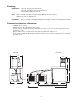
Plumbing Dispenser Note: 3/4" PVC slip joint for hopper drain 3/4" PVC pipe nipple for beverage drain pan 3/8 ID red line tubing for water in Drains should be hard piped and insulated.
Field wiring: Model Circuits required EU155N 230V 50Hz, (1) circuit required Field wiring diagrams Automatic load units IMPORTANT Field wiring diagram is intended to aid electrician or technician in understanding how equipment works.
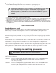
Installation Installing EU155N dispenser in counter ! All EU155N dispensers must be installed level in both directions and supported from below with 153 – 229mm adjustable legs provided, or channels installed on site. DO NOT hang dispenser on flange of counter. 1. Check that dispenser location meets all requirements in this manual and cut counter as shown. 2. Block up area below counter cut-out to support dispenser when lowered into place. 3.
Installing remote icemaker (automatic load units only) ! Correct installation of remote icemaker(s) is critical to proper performance of icemaker and dispenser. Check to make sure bin signal on icemaker control board is switched to 24 volt connection. Refer to installation manual packed with icemaker for important details on ice transport tube run, ventilation requirements and other installation requirements. Failure to comply with instructions will void warranty. 1.
To start up and operate dispenser 1. Follow detailed cleaning instructions in service manual before operating dispenser. 2. For manual load units, remove front drain pan or rear lid and fill storage area with compatible ice. ! Follett manual load dispensers can accommodate most cube/cubelet ices up to 26mm square and Follett compressed nugget ice. Crushed, flake, nugget, bagged or congealed ice cannot be used. Use of these ices can jam dispenser and void warranty.
Cleaning bin before use 1. Wipe storage area with Solution A. 2. Rinse thoroughly with clear, potable water. 3. Wipe with Solution B to sanitize. Periodic cleaning of dispenser Recommended daily cleaning of drain pan ! DO NOT run plastic parts (drain pan, dispense chute cover, dispense wheel) through a dishwasher. 1. Remove all debris from drain pan. 2. Pour 1 gallon (4L) hot water into drain pan to keep drain lines clear. Recommended weekly cleaning 1.
Disassembly instructions for periodic cleaning Fig. 1 Dispense chute cover removal Front view right-hand unit 1. Remove top cover. 2. Push chute cover up vertically to slip off holding tab. 3. After clearing tab, pull chute cover forward to remove. Dispense mechanism assembly removal 1. 2. 3. 4. top cover chute cover drain pan assembly Remove top cover. Remove chute cover (see above). Remove auger motor assembly (see above).
Fig. 3 side view front view auger auger tube dispense wheel auger motor (side view) stationary agitator rotating agitator wheel motor auger bearing plate baffle plate wheel motor mounting plate 2 Service Disassembly instructions for service requirements only – NOT required for any cleaning procedure Dispense wheel motor removal (Fig. 3) 1. 2. 3. 4. 5. 6. Remove drain pan, bin access cover and dispense wheel. Remove stainless steel baffle plate under dispense wheel.
Wiring diagrams WATER SWITCH C L2 WATER SOLENOID NO Wht Blk Orn L1 AUGER MOTOR COUNTERCLOCKWISE ROTATION INterlock RELAY R3 DISPENSE RELAY R1 Orn BLK 4 Pur 4 7 Red Pur Red Wht Blk M1 7 PL2-1 POWER PL2-2 PL2-3 Blu Blu WHEEL COUNTERCLOCKWISE ROTATION AUTOFILL R2 Pur Red Red 1 Wht Blk M2 7 PL3-2 PL3-3 AUTOFILL R2 Orn Blu 9 6 Blk Blu PL3-1 Wht 220 Volts T1 Red Yel 24 Volts DISPENSE SWITCH EU155N Right hand dispenser DISPENSE RELAY Red Brn C Yel R1 NO B
Before calling for service 1. Check that there is ice in dispenser and that congealed cubes are not causing a jam. 2. Check that circuit breaker and switches are in “ON” position. 3. Check that drain pan, rear lid and top are on securely. If ajar, dispenser will not operate. When the top is off, auger does not operate, even though the solenoids do. 4. Check that all drains are clear.
Replacement parts Dispenser exterior Front view right hand (RH) tower (push button dispensing) Top view unit with right hand (RH) tower 8 6 7 17 9 10 2 12 5 14 1 13 3 3 4 Reference # 1 2 3 4 5 6 Not shown 7 8 9 10 11 Not shown 12 13 Not shown 14 Not shown 16 Not shown Not shown Not shown Not shown Not shown Not shown 17 Not shown Not shown 11 15 17 4 16 Description Label, “Follett” Top cover (includes label and magnet) Drain pan (includes magnet) Grille, drain pan Cover, electrical component
Dispense assembly – side view Dispense assembly side view (RH unit shown) 5 3 9 top view 1 9 6 7 2 11 4 8 10 Reference # 1 2 3 4 5 Not shown 6 7 8 9 10 11 Description Gate, dispense Linkage pin, gate/solenoid Pin, quick release, 141mm, dispense gate Solenoid (includes linkage pin) Dispense mechanism assembly, right hand unit Dispense mechanism assembly, left hand unit Spring, dispense mechanism (1 per side) Chute, ice Wrap, dispense mechanism Bushing, Ni liners Screw, 8-32 x 5/16 Pin, spring 15
Hopper – side view 5 1 7 9 3 8 11 2 6 10 4 2 Reference # 1 Not shown 2 Not shown Not shown 3 4 Not shown 5 6 Not shown Not shown Not shown 7 8 9 Not shown Not shown Not shown Not shown Not shown 10 11 Not shown Not shown Not shown Description Auger, LH unit (black, stamped with “1”) Auger, RH unit (gray, stamped with “2”) Plate, auger bearing Tube, auger, right hand unit Tube, auger, left hand unit Wheel, dispense (includes stud and rotating agitator) Baffle (under dispense wheel) Drive bar (under di
Auger motor top view side view 7 6 3 4 10 6 5 9 1 8 2 11 Reference # 1 2 3 4 5 6 7 8 9 10 11 Description Auger motor/drive assembly, vertical (includes all items below) Motor, vertical auger (includes gearbox and capacitor) Chain, auger drive #35, 40p Sprocket 35#, 22T 5/8 bore Sprocket 35#, 12T 5/8 bore Drive shaft Bearing, auger, upper and lower Cover and bearing, chain drive (includes 501314) Capacitor, 25mf, 270V Key, Woodruff Washers, thrust (4) Mounting plate, auger motor (includes 501314) 1
Electrical components 14 6 11 8 13 1 9 9 15 10 5 11 7 Reference # 1 2 3 4 5 6 7 8 9 10 11 13 14 Not shown 15 Not shown Not shown Not shown 4 3 7 6 15 2 Description Transformer, 24V Relay, dispense Relay, auto fill Timer, auto fill (automatic fill units) Strip, terminal Tube, water dispense, stainless steel Bracket, water solenoid Fitting, outlet, 1/8 MPT x 3/8, compression Valve, solenoid, water Fitting, inlet, plastic, 1/4 barb Tubing, water (sold by the foot) Switches (power and icemaker) Bra
801 Church Lane • PO Box D, Easton, PA 18044 Cool Ideas For Ice Management (610) 252-7301 • FAX (610) 250-0696 • www.follettice.