25 and 50 Series Ice and Water Dispensers Order parts online www.follettice.com Installation, Operation and Service Manual 25CT400A/W 50CT400A/W (shown with SensorSAFE™ accessory) 25CR400A/W 50CR400A/W 25HT400A/W 50HT400A/W (shown with SensorSAFE accessory) 25HR400A/W 50HR400A/W 25FB400A/W 50FB400A/W (shown with SensorSAFE accessory) Following installation, please forward this manual to the appropriate operations person.
Table of contents Before you begin Specifications Field wiring Installation Installing freestanding dispensers Installing countertop dispensers Installing wall mount dispensers Installing Satellite-fill™ icemakers Installing top mount icemakers User information Cleaning and sanitizing procedures Service Information Wiring diagram – lever models Wiring diagram – SensorSAFE models Dispenser troubleshooting Troubleshooting SensorSAFE board and sensors Disassembly and replacement instructions Thermostat locatio
Welcome to Follett Follett equipment enjoys a well-deserved reputation for excellent performance, long-term reliability and outstanding after-the-sale support. To ensure that this equipment delivers that same degree of service, we ask that you review the installation portion of this manual before beginning to install the unit. Our installation instructions are designed to help you achieve a trouble-free installation.
Specifications Electrical 1. Models with Satellite-fill icemakers (25CR400A/W, 50CR400A/W, 25HR400A/W, 50HR400A/W) Basic electrical: 115V/60Hz/1 phase 2. Max. fuse 20 amps Dispenser 4.0 amps Max. fuse 20 amps Freestanding models and models with integral icemakers (25FB400A/W, 50FB400A/W, 25CT400A/W, 50CT400A/W, 25HT400A/W, 50HT400A/W) Basic electrical: 115V/60Hz/1 phase 3. Icemaker 11.0 amps Total system 14.0 amps Max.
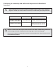
Field wiring for countertop and wall mount dispensers with Satellite-fill icemakers ! ! All field wiring must be installed in accordance with NEC and local electrical codes. Field wiring diagram is intended only to aid electrician or technician in understanding how equipment works. Model Electrical connection Circuits required 25FB400A/W, 50FB400A/W cord & plug provided 115/60/1, 20 amp max.
Field Wiring diagrams (For installations requiring hard-wiring equipment) Freestanding dispensers, countertop and wall mount dispensers with integral icemakers IMPORTANT Electric Power Source FIELD WIRING DIAGRAM IS INTENDED TO AID ELECTRICIAN OR TECHNICIAN IN UNDERSTANDING HOW EQUIPMENT WORKS. ALL FIELD WIRING MUST BE INSTALLED IN ACCORDANCE WITH NEC AND LOCAL ELECTRICAL CODES. GND B W X GRN DISPENSER JUNCTION BOX LEGEND Standard electrical - 115V, 1 Ph, 60 Hz, max.
Installation procedure Before you begin • All dispensers must be installed level in both directions to ensure proper operation • Required ventilation and recommended service clearances: • Countertop and wall mount models with Satellite-fill icemaker (25CR400A/W, 25HR400A/W, 50CR400A/W, 50HR400A/W) — none. 12" (305mm) at top recommended for service • Countertop and wall mount models with integral icemaker (25CT400A/W, 25HT400A/W, 50CT400A/W, 50HT400A/W) — 6" (153mm) at top.
Fig. 1 – Rear connections, freestanding models access panel (B) 3/4" FPT drain power cord .8" (20mm) (A) 3/8" FPT water inlet (D) 3/8" FPT condenser inlet location (water-cooled only) (E) 3/8" FPT condenser outlet location (water-cooled only) 10.5" (267mm) 31.5" (800mm) (C) 3/4" MPT icemaker drain location (water-cooled only) 6.75" (171mm) 15.125" (384mm) 10.25" (259mm) 3.125" (79mm) 3.
Installing countertop dispensers ! Dispensers with top mount icemakers cannot be mounted on legs. They must be bolted to counter. Use gloves when lifting icemaker to protect hands from sheet metal edges. 1. Position dispenser in desired location, mark dispenser outline on counter and remove dispenser. Fig. 2 – Counter cut-out, all models 2. Drill four 3/8" (5mm) holes in counter (Fig. 2) to anchor dispenser to counter. .
5. If power is to be supplied through counter cut-out, complete steps 6-9. If power is to be supplied through rear of dispenser, proceed to step 10. 6. Temporarily remove rear access panel (Figs. 4 and 5) from rear of dispenser. 7. Loosen junction box mounting screws. Lift junction box and power cord up until cord and mounting screws clear notches on rear panel of dispenser. Remove Phillips head screws from right side of junction box. 8.
Installing wall mount dispensers 1. Install supplied wall bracket with six 3/8" diameter fasteners as shown in Fig. 7. Note: Three holes are available at each fastening site to allow capture of studs/support within wall. Steps 2 - 3 are required for models with integral icemaker only (25HT400A/W and 50HT400A/W). 2. For models with integral icemaker, use straight edge to position filler strip flush with top edge of wall bracket. 3. Fasten filler strip to wall as shown in Fig. 8. 4.
8. Remove utility knock-out (Fig.4, 5F) from rear of dispenser and install supplied protective grommet. For dispensers using remote icemakers, remove ice transport tube knock-out (Fig. 5G) from rear of dispenser. 9. Run water supply line from back through utility knock-out (Fig. 5F) and connect water supply line to 3/8" FPT fitting on utility flange at bottom of dispenser (Fig. 3G). 10. Connect and run a dedicated drain line from 3/4" drain tube to wall or floor drain. An air break should be provided. 11.
Installing Satellite-fill icemakers Models 25CR400A/W, 50CR400A/W, 25HR400A/W, 50HR400A/W ! See Icemaker Installation Manual (form #208600) for critical installation instructions for Satellitefill icemakers. Failure to comply with these instructions will result in poor performance and void warranty. 1. Install Satellite-fill icemaker following instructions in icemaker manual. 2. Run uninsulated ice transport tube from dispenser through ice transport tube knock-out (Fig.
Installing top mount icemakers Models 25CT400A/W, 50CT400A/W, 25HT400A/W, 50HT400A/W ! Dispensers with top mount icemakers cannot be mounted on legs. They must be bolted to counter. Use gloves when lifting icemaker to protect hands from sheet metal edges. 1. On dispensers equipped with top-mounted, water-cooled icemakers, feed condenser supply and drain lines from back through utility knock-out (Fig. 4F) or through counter, as appropriate. Connect condenser supply line to inlet fitting (Fig.
Fig. 11 – Ice transport tube and ice level control stat mounting units with top-mounted icemakers ice level control stat .75" (19mm) Hand bend cap tube end to approx.
User information How the dispenser works Follett’s 25 and 50 automatic load ice and water dispensers receive ice from Follett’s 400 lb (181kg)/day icemaker located in the dispenser base, in the cabinet top or in a remote location up to 20 ft (6m) away. Ice produced is stored in the bin section of the dispenser. When the dispense lever is pushed, the wheel motor is energized, causing the wheel to turn. This moves ice to the dispense chute where it drops by gravity into the container held below the chute.
If dispenser is a SensorSAFE unit: 3. Deactivate dispenser by depressing and releasing clean switch located on left side of unit under top front cover. 4. Clean lens using soft cloth and mild, non-abrasive cleaner. 5. Reactivate dispenser by depressing and releasing clean switch a second time (dispenser automatically reactivates after two minutes).
Service information Wiring diagrams How unit works — lever models The dispense wheel motor is energized through the power and ice dispense switches. The water solenoid valve is energized through the power and water dispense switches. The icemaker receives the bin signal through the power switch, the normally closed bin thermostat and the icemaker switch. When the bin level thermostat is calling for ice, a 115v bin signal is applied to the bin signal terminals on the icemaker circuit board.
How unit works — SensorSAFE models SensorSAFE models provide “touchless” ice and water dispensing. When a container is placed within the actuation zone below the ice or water chute on SensorSAFE dispenser models, an infrared signal reflects off the container and is detected by the sensor. The sensor then sends a signal to the control board to activate the appropriate components to dispense ice or water. LEDs on the board indicate when the board is receiving a signal from the sensors.
Dispenser troubleshooting ! Disconnect power to dispenser and icemaker before putting hands or arms in storage area, or attempting any repair or service to equipment. Before calling for service: • Check that there is ice in dispenser bin area • Check that all switches and circuit breakers are on • Check that congealed cubes are not causing a jam • Check that all drains are clear Symptom 1. Does not dispense ice a. b. c. d. e.
Troubleshooting SensorSAFE board and sensors Board guide LEDs, when illuminated, indicate the following: Terminals: L1 (incoming power, hot) L2 (neutral terminals) WTR (power terminal for water solenoid) SOL (power terminal for dispense gate solenoid) not used WM (power terminal for wheel motor) CLN (terminals for clean cycle switch) PWR (board power) CLN (cleaning, no dispensing cycle) ICE (ice dispensing activated) WTR (water dispensing activated) Problem: Does not dispense ice or water Action PWR Chec
Lens/sensor troubleshooting 1. Turn dispenser power switch off. 2. Remove splash panel. 3. Disconnect wires from output terminal(s) (WTR, WM) on board. 4. Gently remove appropriate sensor/mounting block assembly from panel by moving block sideways until edge of block clears retaining tab of panel. 5. Inspect lens and sensor assembly for foreign material and remove using non-abrasive cleaner. 6.
Disassembly and replacement instructions Dispense chute removal 1. Remove dispenser front cover. 2. Slide plastic dispense chute cover up and out to remove. 3. Pull out four white plastic fasteners and remove dispense chute. Dispense wheel removal and installation Note: Models with top mount icemakers require removal of icemaker before removing wheel. 1. Remove all ice from storage area of dispenser. 2. Remove center thumbnut from dispense wheel. 3.
Ice transport tube replacement Models 25FB400A/W, 50FB400A/W, 25CR400A/W, 50CR400A/W Correct installation of ice transport tube is critical to Satellite-fill icemaker performance. Replacement ice transport tubes for Satellite-fill icemakers must be insulated and run continuously from icemaker t o dispenser with no dips or bends with a radius of less than 6" (153mm). ! 1. Remove top and rear access panel from dispenser (lower front panel in freestanding unit). 2.
Thermostat locations Thermostat locations – 25CT400A/W, 25HT400A/W, 50CT400A/W, 50HT400A/W ice deflector bracket assembly rubber grommet ice level control stat ice level control stat bin thermostat control box assembly hopper assembly control box assembly ice level control stat .75" (20mm) Hand bend cap tube end to approx.
Parts Dispenser exterior 7 6 2 2 4 9 3 1 5 Part # 502679 502680 502677 502678 502694 502681 501100 502682 502683 502688 502684 502699 502088 502298 00112854 502700 502778 502701 00109728 502776 502777 502359 502816 502817 502788 502786 502805 10 8 Description Cover, top front, 25 countertop (CT) & wall mount (HT) units Cover, top front, 50 countertop (CT) & wall mount (HT) units Cover, top front, 25 countertop units with Satellite-fill icemaker (CR), wall mount (HR) units & freestanding (FB) Cover, to
Dispense chute and splash panel areas — lever models 2 7 13 4 10 8 14 12 11 1 6 5 3 15 9 Part # 502057 502356 502681 502359 Description Fastener, dispense chute bracket Tube, water station Cover, dispense chute Switch, dispense, ice, lever actuated (includes 501841) 502359 502247 502358 502689 502249 502357 Switch, dispense, water, lever actuated (includes 501841) Bracket, chute (includes fasteners 502057) Lever, dispense Chute and funnel, ice Chute, water Solenoid assembly, water (includes 502
Dispense chute and splash panel areas — SensorSAFE models 10 12 8 3 15 13 11 9 1 14 7 2 5 4 6 Part # 502057 502681 502689 502249 00129908 00129155 502247 502690 502695 502715 502357 502355 502356 502246 502262 502243 00122978 203611 Description Reference Fastener, dispense chute bracket 1 Cover, dispense chute (includes labels) 2 Chute and funnel, ice 3 Chute, water 4 Chute and funnel, ice, wall mount, no drain pan Not shown Chute, water, wall hung, no drain pan Not shown Bracket, chute (includes
Electrical box (front view) – SensorSAFE models Part # 500514 502209 502209 502242 502359 501841 Description Thermostat, bin level Switch, dispenser power Switch, icemaker bin signal Control board, SensorSAFE Clean switch, SensorSAFE Boot, clean switch 1 Reference 1 2 2 3 Not shown Not shown 3 2 2 Wheel motor and drive system 3 8 7 5 4 3 2 6 7 1 1 Part # 501861 501026 501607 501619 502691 502692 501019 501024 500799 500637 502020 Description Wheel motor, 120V, 60Hz Washer, thrust Fan blade, w
Hopper components Top view – all top mounted units Top view – freestanding and Satellite-fill units 6 16 13 15 2 18 5 4.
Ice transport tubing Part # 502522 502523 501176 502328 502329 502697 Description Ice transport tube (Satellite-fill units) - 10 ft Ice transport tube (Satellite-fill units) - 20 ft Ice transport tube insulation (Satellite-fill units only) - sold by the foot Ice transport tube assembly (50 freestanding (FB) units) Ice transport tube assembly (25 freestanding (FB) units) Ice transport tube assembly (top mount units) Reference Not shown Not shown Not shown Not shown Not shown Not shown Chilled water compon
Countertop dispenser plumbing connections 1 Mounting plate fittings 2 3 7 4 6 5 Part # 00136663 502222 502685 502100 502682 502718 502433 Description Strainer Valve, water shut-off Drain tube assembly Fitting, water inlet with mounting plate Drain pan Elbow Tee, water inlet Reference 1 2 3 4 5 6 7 1 Bulkhead fittings 2 3 7 4 6 5 Part # 00136663 502222 502685 00151134 502682 00149674 502433 Description Strainer Valve, water shut-off Drain tube assembly Fitting, water inlet Drain pan Elbow Tee, wa