
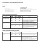
corp. Ice and Water Dispensers 25, 50

Ice transport tube replacement
Models 25FB400A/W, 50FB400A/W, 25CR400A/W, 50CR400A/W
1. Remove top and rear access panel from dispenser (lower front panel in freestanding unit).
2. Disconnect existing ice tube from engaging pin on transport tube bracket in ice storage bin and pull down through
dispenser chase.
3. Disconnect opposite end of tube from icemaker.
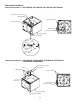
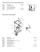
4. Run end of new ice transport tube with 3/16" (5mm) hole through ice transport tube knockout (Fig. 5G) in back of
dispenser or through counter into bottom of dispenser, being careful to avoid any bends with less than 6" (153mm)
radius.
5. Insert tube in internal chase in rear inside corner of dispenser (left side as you face dispenser) and push up into
storage area.
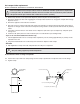
6. Push the 3/16" (5mm) hole near end of tube into pin on ice tube bracket (see drawing below).
Steps 7-8 for units with Satellite-fill icemakers only
7. Install supplied insulation to run of transport tube required for your site, leaving approximately 2" (51mm) of tube
exposed at free end.
8. Check that insulated tube runs continuously from icemaker to dispenser with no dips.
All units
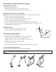
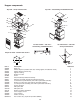
9. Slip supplied hose clamp onto tube and push tube onto exit port of evaporator.
Do not twist hose when securing to evaporator.
10. Fasten tube on port with hose clamp, being sure that clamp is positioned on evaporator side of nozzle flange.
11. Tighten clamp.
Correct installation of ice transport tube is critical to Satellite-fill icemaker performance. Replacement
ice transport tubes for Satellite-fill icemakers must be insulated and run continuously from icemaker t
o dispenser with no dips or bends with a radius of less than 6" (153mm).
!
engaging pin
3/16 (5mm) ice tube hole
ice hose mounting bracket
ice level control stat
ice tube
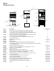
1"
(26mm)
A
A
1"
(26mm)
Section A – A
.3/16" (5mm)
dia. hole
Only use tubing supplied by Follett Corporation.
!
24