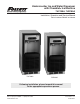
Undercounter Ice and Water Dispenser with Chewblet® Ice Machine 7UC100A, 7UD100A Installation, Operation and Service Manual Serial numbers E01087 and above 7UC100A 7UD100A Following installation, please forward this manual to the appropriate operations person. 801 Church Lane • Easton, PA 18040, USA Toll free (877) 612-5086 • +1 (610) 252-7301 www.follettice.com Order parts online: www.follettice.
Undercounter Dispenser and Ice machine 7UC100A/7UD100A
Contents Welcome. . . . . . . . . . . . . . . . . . . . . . . . . . . . . . . . . . . . . . . . . . . . . . . . . . . . . . . . . . . . . . . . . . . . . . . . . . . . . . . . . . . . . . 4 Before You Begin. . . . . . . . . . . . . . . . . . . . . . . . . . . . . . . . . . . . . . . . . . . . . . . . . . . . . . . . . . . . . . . . . . . . . . . . . . .
Welcome––––––––––––––––––––––––––––––––––––––––––––––––––––––––––– Follett equipment enjoys a well-deserved reputation for excellent performance, long-term reliability, and outstanding after-the-sale support. To ensure that this product delivers that same degree of service, we ask that you take a moment to review this manual before beginning the installation. Should you have any questions or require technical help at any point, please call our technical service group at (877) 612-5086 or +1 (610) 252-7301.
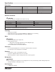
Specifications–––––––––––––––––––––––––––––––––––––––––––––––––––––– Dimensions 7UC100A 7UD100A Width 14.55" (370 mm) 14.55" (370 mm) Depth 22.05" (560 mm) 22.05" (560 mm) Height 33.50" (851 mm) 31.50" (800 mm) Unit Shipping Weight 110 lb (50 kg) 110 lb (50 kg) Ambient Information CAUTION! The 7UC100A and 7UD100A are for indoor use only. Maximum* Minimum* Air Temperature 100 F (38 C) 50 F (10 C) Water Temperature 90 F (32.2 C) 40 F (4.
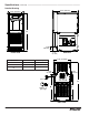
Specifications (continued)––––––––––––––––––––––––––––––––––––––––––––––– Detailed Drawing 22.05" (560 mm) 14.55" (370 mm) A 4.00" (102 mm) FRONT VIEW Dimension 3.81" (97 mm) 7UC100A 7UD100A (ADA) A 33.50” (851 mm) 31.50” (800 mm) B 22.76” (578 mm) 20.76” (527mm) C 22.69” (576 mm) 20.69” (526 mm) SIDE VIEW 14.55" (370 mm) 2.40" (61 mm) 2.
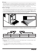
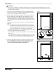
Installation––––––––––––––––––––––––––––––––––––––––––––––––––––––––– CAUTION! No service or maintenance should be performed until the technician has thoroughly read this service manual. Except for routine cleaning and sanitizing, only qualified technicians should attempt to service or maintain this equipment. 1. Measure to verify that the dispenser will fit in the desired location. A clearance of at least 3" (77 mm) is required behind the dispenser for the electrical and optional drain connection. Fig.
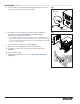
Installation (continued) –––––––––––––––––––––––––––––––––––––––––––––––––– 5. Connect water line. Recommended routing (Fig. 3) allows easy access to water for cleaning and sanitizing procedure. Fig. 3 3' (91.4 cm) Plug Valve 1/4" MPT 6. If installing the optional internal water filter*, please complete the steps shown in Cleaning and Sanitizing on page 11 before proceeding. If not, proceed to step 10.
Maintenance/Cleaning Mode–––––––––––––––––––––––––––––––––––––––––– Fig. 5 Cleaning Mode (Dispensing Disabled) - Use when cleaning surface Entering Cleaning Mode disables the User Interface and allows you to clean the outside of the dispenser without accidentally dispensing water or ice. 2 1. To enter Cleaning Mode, press and immediately release the maintenance/clean switch (Fig. 5.1) so that only "FRESH FILTERED ICE AND WATER" displays in the user interface (Fig. 5.2). 1 2.
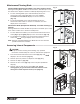
Filter Display Indicator Activation–––––––––––––––––––––––––––––––––––––– If you purchased your dispenser with a Follett filter, the filter display indicator Fig. 7 activation has been preset at the factory. If you are using an “after market filter,” an adjustment may be made to activate the “Fresh Filtered Ice & Water” display. 1 Activating “Fresh Filtered Ice & Water” 1. Remove the front panel as explained in Accessing Internal Components on page 9 then refer to Fig. 7. 2. Remove top panel (Fig. 7.1).
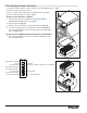
Cleaning and Sanitizing–––––––––––––––––––––––––––––––––––––––––––––– Cleaning and sanitizing should be performed at least every 6 months (more often if local water conditions dictate). For initial startup, only sanitizing is required. Fig. 9 IMPORTANT! Prior to cleaning and sanitizing, the dispenser must be moved forward at least 4" (10.16 cm). Do not remove the Bin Lid, cleaning and sanitizing solution is added through the Bin Lid Access Spout (Fig. 9.6).
Cleaning and Sanitizing (continued)––––––––––––––––––––––––––––––––––––––– Cleaning: User Interface and Exterior Cabinet 1. Press and release maintenance/clean switch so that only "FRESH FILTERED ICE AND WATER" displays in the user interface to enter Cleaning Mode (and disable dispensing). 2. Plastic parts, including the user interface, can be cleaned with a non-abrasive glass cleaner. Clean stainless steel panels with stainless steel cleaner. 3.
Service (continued)––––––––––––––––––––––––––––––––––––––––––––––––––––– Evaporator Disassembly Fig. 11 1. Disconnect power from the dispenser. 2. Turn off water supply to dispenser. 2 3. Remove (unscrew) chrome ice dispenser chute (Fig. 11.1). 4. Remove the drip tray (Fig. 11.2). 5. Remove the two screws (Fig. 11.3) on the front panel (behind the drip tray). 1 6. Remove and set aside the front panel (Fig. 11.4) - do not disengage the plug on the back of the User Interface. 7.
Service (continued)––––––––––––––––––––––––––––––––––––––––––––––––––––– 10. Unplug the gear motor (three connectors) (Fig. 12). Fig. 12 11. Remove ground screw connection. 12. Remove gear motor: Fig. 13 §§ Remove M6 allen screw, retainer, spacer and key (Fig. 13.1). §§ Remove two M6x90 allen screws (Fig. 13.2). §§ Pull gear motor from auger (Fig. 13.3). §§ Remove main housing insulation (Fig. 13.4). 13. Remove all traces of petro-gel from auger shaft. 4 2 3 1 2 14.
Service (continued)–––––––––––––––––––––––––––––––––––––––––––––––––––– 15. Remove M6 socket head allen screw (Fig. 15.1). Fig. 15 16. Remove compression nozzle retainer (Fig. 15.2). 1 17. Remove compression nozzle (Fig. 15.3). 2 3 18. Remove main housing: Fig. 16 §§ Disconnect vent line from T fitting (Fig. 16.1). 1 19. Remove three M6x25 socket head allen screws (Fig. 17.1). Fig. 17 20. Remove main housing (Fig. 17.2).
Service (continued)–––––––––––––––––––––––––––––––––––––––––––––––––––– 21. Remove and discard mating ring and seal (Fig. 18.1). Fig. 18 22. Carefully remove auger (Fig. 18.2). WARNING! Use caution when removing auger. The auger is very sharp - handle with care to avoid personal injury. 2 1 Evaporator Assembly Fig. 19 1. Remove and inspect main housing O-ring seal. Replace if damaged in any way. 2. Clean O-ring groove. Lubricate O-ring with Petro-gel and reinstall. 3.
Service (continued)–––––––––––––––––––––––––––––––––––––––––––––––––––– 7. Install compression nozzle: Fig. 21 §§ Remove and inspect compression nozzle O-ring seal. Replace if damaged in any way. §§ Clean O-ring groove. Lubricate O-ring with Petro-gel and reinstall. §§ Install compression nozzle (Fig. 21.1). §§ Install compression nozzle retainer (Fig. 21.2). §§ Install M6 socket head allen screw (Fig. 21.3). 3 2 1 8. Install transport tube (Fig. 22.1). Fig. 22 9. Tighten hose clamp (Fig. 22.2).
Service (continued)–––––––––––––––––––––––––––––––––––––––––––––––––––– 11. Use screwdriver to orient auger shaft to align with motor shaft keyway (Fig. 24.1). Fig. 24 12. Install key into keyway (Fig. 24.2). 2 1 13. Install spacer, ensure that key is captured in slot (Fig. 25.1) Fig. 25 1 14. Insert screwdriver into groove of auger shaft and pry shaft outwards (Fig. 26.1). Fig. 26 15. Insert retainer into groove (Fig. 26.2), ensure that retainer is aligned with hole in spacer.
Service (continued)–––––––––––––––––––––––––––––––––––––––––––––––––––– 16. Install screw and tighten (Fig. 27.1). Fig. 27 1 2 17. Plug in gear motor (Fig. 28). §§ §§ §§ §§ Fig. 28 BLUE to BLUE BLACK to BLACK WHITE to WHITE Connect ground wire with ground screw.
Service (continued)––––––––––––––––––––––––––––––––––––––––––––––––––––– Water Feed Schematic Evaporator Float Water Chute (optional) Filter (optional) Water Solenoid Valve (optional) Water Solenoid Valve 20 Undercounter Dispenser and Ice machine 7UC100A/7UD100A
Service (continued)––––––––––––––––––––––––––––––––––––––––––––––––––––– Bin Melt Water/Evaporator Feed/Clean Out System Schematic Storage Bin Vent System Schematic Storage Bin Vent Tube Reservoir Undercounter Dispenser and Ice machine 7UC100A/7UD100A 21
Service (continued)––––––––––––––––––––––––––––––––––––––––––––––––––––– Refrigeration Schematic CONDENSER FILTER-DRIER CAP TUBE COMPRESSOR EVAPORATOR ACCUMULATOR 22 HIGH PRESSURE VAPOR LOW PRESSURE LIQUID HIGH PRESSURE LIQUID LOW PRESSURE VAPOR Undercounter Dispenser and Ice machine 7UC100A/7UD100A
Service (continued)––––––––––––––––––––––––––––––––––––––––––––––––––––– Condenser Fan Motor Removal Undercounter Dispenser and Ice machine 7UC100A/7UD100A 23
Service (continued)––––––––––––––––––––––––––––––––––––––––––––––––––––– User Interface Display Identification Operation Display Condition Procedure Normal operation PM — Cleaning Mode Press and release maintenance/clean switch to clean the user interface without dispensing ice or water (see Maintenance/Cleaning Mode on page 9). Drip tray full Empty drip tray. Six-month periodic maintenance required Follow Maintenance Mode procedure (below) and also see Cleaning and Sanitizing on page 11.
Service (continued)––––––––––––––––––––––––––––––––––––––––––––––––––––– RESERVOIR WATER SENSOR DRIP TRAY WATER SENSOR POWER CHASSIS WATER SENSOR BIN MAINTENANCE CLEAN USER INTERFACE Electrical Wiring Diagram Undercounter Dispenser and Ice machine 7UC100A/7UD100A 25
Parts–––––––––––––––––––––––––––––––––––––––––––––––––––––––––––––– Exterior 6 4 7 11 5 10 9 2 8 26 1 Undercounter Dispenser and Ice machine 7UC100A/7UD100A 3
Parts (continued)––––––––––––––––––––––––––––––––––––––––––––––––––––––– Exterior Reference # Description Part # 1 Drain, Tray Assy 00957613 2 Panel, Front Assy - Includes Water Nozzle and Plug 00957621 3 Chute, Water (water option) 00957688 4 Panel, Top Left 00924761 5 Panel, Top Right 00924779 6 Panel, Top 00957654 7 Panel, Rear 00957662 Panel, Lower, 7UC100A Height: 12.0" (304.8 mm) 00924738 Panel, Lower, 7UD100A Height: 10.
Parts (continued)––––––––––––––––––––––––––––––––––––––––––––––––––––––– Interior 4 7 3 1 12 2 10 10 6 5 11 14 9 8 13 28 Undercounter Dispenser and Ice machine 7UC100A/7UD100A
Parts (continued)––––––––––––––––––––––––––––––––––––––––––––––––––––––– Interior Reference # Description Part # 1 Valve, Dispense Solenoid (water option) 00957704 2 Switch, Cleaning 00957712 3 Drain/Feed Tube with Cap 00957720 4 Valve, Failsafe Solenoid 00957738 5 Compressor with Mounting Hardware 00958009 6 Condenser 00958017 7 Condenser Fan and Cord 00958025 8 Control Board with Stand-offs 00958033 9 Capacitor, Gearmotor 00958041 10 Sensor, Retainer Hardware Kit 00958066
Parts (continued)––––––––––––––––––––––––––––––––––––––––––––––––––––––– Bin Assembly 9 3 4 5 6 2 1 7 8 30 Undercounter Dispenser and Ice machine 7UC100A/7UD100A
Parts (continued)––––––––––––––––––––––––––––––––––––––––––––––––––––––– Bin Assembly Reference # Description Part # 1 Ice Chute Assembly 00957670 2 Ice Transport Tubing with Insulation 00957746 3 Switch, Shuttle 00957753 4 Shuttle, Complete Assy 00957761 5 Lid, Bin Assy 00957779 6 Bin, Assy 00957787 7 Auger, Dispense 00957795 8 Motor, Dispense 00957803 9 Cap and Insulation, Bin 00957936 Not Shown For serial numbers D17619 and below: Bin Cap 00931519 Ice Chute 00927210 C
Parts (continued)––––––––––––––––––––––––––––––––––––––––––––––––––––––– Evaporator Assembly 10 11 12 13 14 13 2 8 5 6 1 3 7 4 9 32 Undercounter Dispenser and Ice machine 7UC100A/7UD100A
Parts (continued)––––––––––––––––––––––––––––––––––––––––––––––––––––––– Evaporator Assembly Reference # Description Part # 1 Gearmotor Assembly 00957811 2 Main Housing with Front Seal and Screws 00957829 3 Screws, Main Housing 00957837 4 Auger with front seal (includes gearmotor hardware kit) 00957845 5 Ice Compression Nozzle Assy 00957852 6 Front Seal and O-Ring 00957860 7 Evaporator Assembly with Insulation 00957878 8 Housing, Bushing with Insulation 00957886 9 Hardware kit,
Undercounter Dispenser and Ice machine 7UC100A/7UD100A
Undercounter Dispenser and Ice machine 7UC100A/7UD100A 35
SafeCLEAN is a trademark of Follett Corporation. Follett is a registered trademark of Follett Corporation, registered in US. 801 Church Lane • Easton, PA 18040, USA Toll free (877) 612-5086 • +1 (610) 252-7301 www.follettice.