
Use and Care


Undercounter Dispenser and Ice machine 7UC100A/7UD100A 7
Installation ––––––––––––––––––––––––––––––––––––––––––––––––––––––––
CAUTION!
No service or maintenance should be performed until the technician has thoroughly read this service
manual. Except for routine cleaning and sanitizing, only qualied technicians should attempt to service
or maintain this equipment.
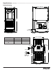
1. Measure to verify that the dispenser will t in the desired location.
A clearance of at least 3" (77 mm) is required behind the dispenser
for the electrical and optional drain connection.
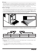
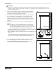
2. Ensure that the nished oor inside the cabinet is ush (level) with
the oor outside the cabinet (Fig. 1). If the cabinet oor is lower
than the nished oor, the cabinet oor must be built up (using
appropriate materials) until it is ush with the nished oor. A ush
oor is required for proper operation and maintenance/service of the
dispenser.
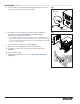
3. Rough-in the electrical service, water line, and optional Drip Tray
Drain Kit*.
Note: The dispenser must be installed such that it can be moved
forward at least 4" (10.16 cm) to allow access to the Bin Lid
Cleaning Spout (Fig. 9.6) for dispenser cleaning and sanitizing.
Take this requirement into consideration during rough-in.
§ Electrical: 115V, single phase, 15A receptacle required. The dispenser
has an integral 8 ft. (2.4 m) cord and plug.
§ Water: supply line (with shut-off valve) connects to the dispenser's 1/4"
MPT inlet.
* The optional Drip Tray Drain Kit (item# 00956375) requires a oor drain
within 15 ft. (4.5 m) of the dispenser. For detailed installation instructions,
please refer to the instructions shipped with the Drip Tray Drain Kit.
Fig. 1
floor
cabinet space
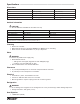
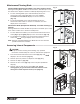
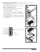
4. Install the angle bracket inside the cabinet,18.15" (461mm) from
the toe kick (Fig. 2.1). The bracket prevents the dispenser from
being located/pushed beyond the recommended cabinet space
depth. Do not attach the bracket to the dispenser.
Fig. 2
1
18.15” (461 mm)