FZR Series Undercounter Freezer Order parts online www.follettice.com Installation, Operation and Service Manual Serial numbers C45184 and above Following installation, please forward this manual to the appropriate operations person. 801 Church Lane • Easton, PA 18040, USA Toll free (800) 523-9361 • (610) 252-7301 Fax (610) 250-0696 • www.follettice.
Welcome to Follett Follett equipment enjoys a well-deserved reputation for excellent performance, long-term reliability and outstanding after-the-sale support. To ensure that this product delivers that same degree of service, we ask that you take a moment to review this manual before beginning the installation. Should you have any questions or require technical help at any point, please call our technical service group at (800) 523-9361 or (610) 252-7301.
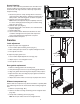
Installation Installing legs – required Fig. 1 1. Remove legs from plastic bag packed inside freezer. 2. Tip freezer back and screw legs in all the way to stop (they will extend 1/8" below base of freezer). 3. Adjust legs as needed to level freezer in both directions. To access legs, remove the lower front panel. Turn legs clockwise to extend legs. Installing shelves – required Fig. 2 1. Remove shelves and shelf brackets packed inside freezer. 2.
Reversing the door swing – optional Fig. 4 NOTICE When reinstalling latch and hinge screws, 242 blue Loctite* MUST be applied to screws. Torque screws to 25 in-lbs. 1. Remove screws and latch from refrigerator cabinet (Fig. 4.1). 2. Use flat screwdriver to carefully remove (do not scratch) hinge covers (Fig. 5.1). 1 3. Support door and remove screws attaching hinge to refrigerator cabinet (Fig. 5.2). 2 4. Cover hinge screw holes with screw hole plugs removed from opposite side. 5. Reverse door.
Fig. 7 Controller operation In normal operation the controller displays cabinet temperatures in degrees C (default) or user-selected degrees F. Degrees C temperatures are displayed to 1 decimal point. refrigeration system energized Rocker buttons to the right of the temperature display control all programming functions. The controller is pre-programmed with a -25 C (-13 F) set point which provides a compressor cut-in at -23 C (-9 F) and cut-out at -25 C (-13 F).
Controller security The controller panel can be locked to prevent inadvertent or intentional programming changes. In locked mode, the controller will display cabinet temperature and cut-out set point only. To lock the controller 1. Press the UP and DOWN ARROW buttons together for 3 seconds until “PoF” displays (will flash 3 times). 2. Programmer is now locked. To unlock the controller 1. Press UP and DOWN ARROW buttons together for 3 seconds until “Pon” displays (will flash 3 times). 2.
Operation The temperature controller and probe indicate when the refrigeration system is required to turn on and off. The refrigeration system removes heat from the cabinet interior and rejects it to the surrounding room air. When the cabinet interior temperature reaches +2.2 C (+4 F) above the controller set point, the probe signals the controller to turn the refrigeration system on.
Fig. 8 Annual cleaning Removal of dust and other particulates from air intake areas and the condenser is important for proper operation. Some environments with large amounts of dust may require more frequent cleaning. 1. Disconnect power to unit by turning switch on the lower front panel to the OFF position, switching circuit breaker to OFF position, and removing power cord from receptacle. 2. Remove lower front panel (Fig. 8.1).
Controller replacement 1. Disconnect power to unit. a. Push front panel rocker switch to OFF position. b. Disconnect power cord. 2. Remove 6 screws from front panel and slide panel forward to access back of controller. 3. Disconnect front panel and wiring harness from freezer at the 3, 4, and 5 pin connectors and door heater connector to simplify replacement. 4. Push in on center of side brackets (on controller) to release and slide brackets back and off controller. 5.
Refrigeration system The FZR series -20 C (-4 F) freezer refrigeration system is designed to give many years of trouble-free service. Except for routine cleaning of the air-cooled condenser and related parts, the refrigeration system requires no service or maintenance. The system uses a thermostatic expansion valve and is critically charged. Access fittings are provided for ease of service.
Freezer troubleshooting guide Before calling for service 1. Check that unit is plugged in. 2. Test outlet with another appliance to verify power. Symptom Possible cause Solution Freezer does not operate (no components run). 1. Power switch faulty or in OFF position; loose connection. 2. Freezer not plugged in. 3. No power to cord. 4. Temp controller not energizing components. 5. Probe not sensing cut in temperature. 1. Turn power switch to ON position; check switch and connections. 2. Connect plug. 3.
Accessories Temperature alarm Fig. 11 Before installing alarm OFF 1. Remove supplied 9-volt back-up battery from packing box. OFF 2. Remove 2 screws from module face and remove faceplate. OFF OFF 3. Install back-up battery on battery connector. 4. Locate DIP switches on the back of the faceplate (Fig. 11). 5. Review the factory DIP switch settings (Fig. 12) and make any changes required to meet the needs of your specific application. POWER SENSOR OUTPUT 6. Reinstall faceplate. Fig.
Setting alarm temperatures Fig. 15 1. After the installation is complete, allow 30 minutes for the system to stabilize to ambient temperature. 2. Calibrate temperature alarm to refrigerator display a. Calibration is best done with the alarm probe removed from the probe bottle and placed in the vicinity of the temperature controller probe. Allow at least 15 minutes for the probe temperature to stabilize. b.
Replacement parts 11 10 9 5 1 2 4 3 6 8 13 7 12 Evaporator Reference # 1 1 2 3 4 5 6 7 7 8 9 10 11 12 13 Description Cover, evaporator, FZR5 (includes 00152892) Cover, evaporator, FZR4-ADA (includes 00152892) Fan guard Fan blade Bracket, fan motor Fan motor, evaporator Defrost heater Drain pan, evaporator, FZR5 Drain pan, evaporator, FZR4-ADA Evaporator Heater safety switch Expansion valve (includes 00106534) Insulation, bulb Evaporator cover guard Clips, defrost heater (2 needed) 15 Part # 00155
3 2 4 7 1 8 5 6 Condensing Unit Reference # 1 2 3 4 5 6 7 8 Not shown Not shown Not shown Description Condensing unit Condenser Shroud, condenser Condenser fan blade Condenser fan motor Fan motor bracket Compressor Starting capacitor Filter drier Cap, starting capacitor Starting relay Overload protector Part # 00153874 00157339 00157347 00105007 00104992 00157412 00157313 00104968 502724 00105627 00157305 00104984 16
12 11 1 9 3 1 8 10 7 2 6 4 5 Hardware Reference # 1 2 3 3 4 5 6 6 7 7 8 8 9 10 11 12 Not shown Description Latch & striker includes screws Latch screws, 3 per latch Door, FZR5 (includes gasket - 21 3/8" x 21 3/8") Door, FZR4-ADA (includes gasket - 21 3/8" x 18 5/8") Hinge, each - 2 required, includes screws Hinge screws, each - 6 per hinge Gasket, FZR5 Gasket, FZR4-ADA Strip sealer (set of 4) FZR5 Strip sealer (set of 4) FZR4-ADA Door heater, FZR4-ADA (includes 00130146) Door heater, FZR5 (includes 0
6 5 3 2 4 1 Hardware & electrical components Reference # 1 Not shown 2 3 4 Not shown Not shown 5 6 Not shown Not shown Not shown Description Temperature controller Temperature probes & harness Power switch Front panel (includes 00114371 and 00105379) Front panel screws, each - 6 per panel Rear panel, includes screws Rear panel screws, each - 6 per panel Condensate pan Evaporator drain line, sold by the foot Freezer programming key, degrees F Freezer programming key, degrees C Power cord Part # 00900092
801 Church Lane • Easton, PA 18040, USA Toll free (800) 523-9361 • (610) 252-7301 Fax (610) 250-0696 • www.follettice.