
Undercounter Freezer Installation,Operation and Service Manual


Annual cleaning
Removal of dust and other particulates from air intake areas
and the condenser is important for proper operation. Some
environments with large amounts of dust may require more
frequent cleaning.
1. Disconnect power to unit by turning switch on the lower
front panel to the OFF position, switching circuit breaker to
OFF position, and removing power cord from receptacle.
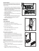
2. Remove lower front panel (Fig. 8.1).
Note: Front louvered panel may be completely removed
for easier cleaning by disconnecting the controller wiring
plugs from the freezer.
3. Remove drain pan (Fig. 8.2).
4. Clean drain pan with a non-abrasive, non-chlorinated all-
purpose detergent.
5. Reinstall drain pan.
6. Use a vacuum cleaner with brush attachment to clean
condenser through lower front panel and compressor
motor and related parts through lower rear panel.
7. Reinstall lower front panel.
Service
Latch adjustment
To adjust for proper latch engagement
1. Loosen striker plate mounting screws (Fig. 9.1).
2. Move striker plate up or down as required and tighten screws.
3. Test operation of latch.
To adjust for proper gasket seal
1. Loosen striker depth adjustment screw (Fig. 9.2).
2. Adjust stop in or out and tighten screws.
3. Test operation of latch.
Door gasket replacement
1. Remove existing gasket from mounting track.
2. Verify mounting track is free of any remaining gasket material.
3. Align new gasket with mounting track and press rmly in place.
4. Open and close door, checking for proper gasket seal without
pinching against freezer.
5. Adjust latch and or striker as necessary for proper door closure.
Slide-out compressor tray
Follett’s slide-out compressor tray allows technicians to partially slide
the condensing unit from the freezer back without cutting refrigerant
lines.
1. Remove rear panel (Fig. 10.1).
2. Remove two bolts securing condensing unit to refrigerator base
(Fig. 10.2).
3. Gently slide condensing unit out (Fig. 10.3).
Note: Do not put undue strain on the refrigerant lines.
9
1
2
Fig. 9
2
0
8
2
6
4
P
r
o
d
u
c
t
M
o
d
u
l
e
N
o
.
S
e
r
v
i
c
e
N
o
.
Easton Pennsylvania
MOTOR COMPRESSOR THER
MALLY PRO
TECTED
DESIGN PRESSURE HIGH SIDE
M
IN
.
B
RAN
CH CIRCUIT AMP
ACITY
MAX. BRANC
H C
IRCUIT FUSE SIZE
SINGLE
PHASE
LOW SIDE
L
THE USA
MA
DE I
N
O
Z
P
S
I
G
R
C
N
S
F
U
L
PART NO
HZ
CHARGE
A
M
P
S
R
A
M
P
S
U
VOLTS
CORPORATION
SERIAL NO
MODEL
FULL LOAD AMPS
REFRIGERANT
1
2
3
Fig. 10
1
2
Fig. 8