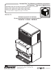
Horizon Elite™ Ice Machine Installation Instructions for Harmony™ Top-mount Applications HCD/HMD710AHT, HCC1010AHT, HCC1410AHT, HCC1010WHT, HCC1410WHT, HMC1010AHT, HMC1410AHT, HMC1010WHT, HMC1410WHT, HCE1010AHT, HCE1410AHT, HCE1010WHT, HCE1410WHT HME1010AHT, HME1410AHT, HME1010WHT, HME1410WHT (See model number configurator on page 2 for details.) Order parts online www.follettice.
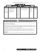
Chewblet® Ice Machine Model Number Configurations HC Icemaker MC Maestro™ Chewblet® (425 Series) HC Horizon Chewblet (710, 1010, 1410, 1810, 2110 Series) HM Horizon Micro Chewblet Voltage D 1810 A V Series 425 up to C 208-230/60/1 (icemaking head) Self-contained only. 425 lbs D 115/60/1 (icemaking head) (193 kg) Self-contained and remote. If remote 710 up to unit, high side is 208-230/60/1. 675 lbs E 230/50/1 (icemaking head) (306 kg) Self-contained only.
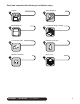
Read and complete the following 8 installation steps 1 3 5 7 Unpack 2 Bin preparation 4 Ice transport tube 6 Internal connection HARMONY • TOP-MOUNT 8 self-contained Site preparation Louvered docking assembly External connection Front cover 3
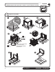
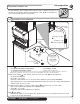
Unpack Carefully unpack and inspect the contents of your Follett ice machine. 1.
Site preparation Prepare the installation site. 2 Provide drainage, water supply and electrical power to within 6 feet (2m) of ice machine in accordance with local and national codes. Outdoor installation is not recommended and will void warranty. 2.1 2.1 Installation site requirements Minimum 8" radius 2 ft. x 1" OD silicone tubing 3/4" barb x 3/4" FPT H_C1010A/W NEMA 6-15 ➋ ➌ NEMA 5-15 H_C1410A/W NEMA 6-20 H_E1010A/W‡ requires 15A circuit, 1.
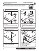
Dispenser preparation Prepare the dispenser. 3 Note: The instructions below only apply to 22" & 30" wide dispensers. 44" wide dispenser instructions may be found with the top kit. 3.1 3.2 Top preparation – ALL Top preparation – ALL ➊ ➊ ➌ ➊ ➊ ➋ All models • Remove protective tape from gaskets ➊ • Apply gaskets ➊. • Install coupling ➋ through bottom of dispenser top and secure with locking nut ➌ 3.3 3.
3.5 Top preparation – LANCER 3.6 Agitation adjust. – CORNELIUS ➊ ON OFF ➋ ➋ Lancer models only • Remove protective tape • Apply gaskets ➋ Adjust the agitation timer located on the Cornelius PC board to 1 second on, 1 hour off. Note: See Cornelius manual for more information. Agitation adjustments – LANCER 4500 SERIES PRESS IN ON THIS SIDE TO TURN SWITCH ON.
3.9 Agitation adjustments – LANCER FS SERIES Initialization Screen (Boot Up Only) Lancer FS-16 Ver. 0.
3.
3.12 Dispenser diverter plate installation – CORNELIUS ED, DF and DB SERIES GATE MOUNTING PLATE STORAGE HOPPER FLANGE EXTENDS INTO STORAGE HOPPER THROUGH GATE OPENING ICE DIVERTER ICE CHUTE COVER APPLY RTV TO THIS SURFACE TO SEAL TO HOPPER GATE MOUNTING PLATE 10-32 WASHER GASKET ICE CHUTE Cornelius ED, DF and10-32 DB NUT series only These dispensers require the installation of an ice diverter at the dispenser opening.
Install the louvered docking assembly. Louvered docking assembly 4 BEFORE PROCEEDING Prior to installing the louvered docking assembly, ensure that the drain fitting is oriented (right or left) correctly for your installation. An optional straight drain fitting is also supplied. You may need to remove the back panel of the docking assembly in order to re-orient or change the drain fitting. Replace back panel prior to mounting the docking assembly. 4.
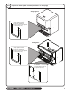
Ice transport tube Install the ice transport tube. 5.
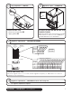
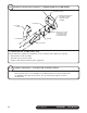
External connections Connect utilities to louvered docking assembly. 6.1 Air-cooled ice machines only 6.2 6 Water-cooled ice machines only ➊ ➊ ➏ ➋ ➋ ➐ ➌ ➌ Minimum 8" radius ➏ Minimum 8" radius ➑ 2 ft. x 1" OD silicone tubing 2 ft. x 1" OD silicone tubing 3/4" barb x 3/4" FPT 3/4" barb x 3/4" FPT ➍ ➍ 3/4" MPT x 1" slip 3/4" MPT x 1" slip ➎1" Stand pipe/Drain • Rough-in ice machine potable water supply ➊.
Internal connections Connect louvered docking assembly to ice machine. 7 CAUTION • Plug must be accessible after final installation. • H_E1410A/W 230/50/1 requires a 20A circuit (4.00 mm2 wire) Air-cooled ice machines – follow steps 7.1 through 7.5. 7.1 7.
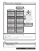
Water-cooled ice machines – follow steps 7.6 through 7.12. 7.6 TDS switch Cooling lines CLEAN POWER ON HIGH LOW BIN MAKING ICE SLEEP CYCLE TIME DELAY LOW WATER MAINT/CLEAN SERVICE HIGH AMPS HIGH PRES TDS DRAIN CLOG CLEANER FULL 7.5 In Out LOW • Set the TDS switch on the electrical box: HIGH: for extended service life LOW: for low-scale water 7.7 • Install ice machine cooling water lines to louvered docking assembly 7.
7.9 7.10 Cooling lines and power Power cord ➋ ➊ • Remove twist tie • Carefully pass cord thru opening and plug into wall outlet • For HCE/HME units, install a suitable plug • Connect cooling water lines to ice machine (Water "Out" connects to water regulator.) ➊ • Water valve is set at the factory. DO NOT remove seal or adjust water valve ➋ Power cord 7.
Front cover Install front cover to ice machine. 8.1 8 Install front cover ➋ ➌ ➊ • Slide ice machine cover over machine ensuring that tabs on back of cover slip under louvers on back of louvered docking assembly ➊ • Insert and tighten two screws through cover and into louvered docking assembly ➋ • For air-cooled machines only, install plastic grill ➌ NOTICE Ice machine MUST be sanitized prior to operation! Consult Operation and Service Manual provided with ice machine for sanitizing instructions.
Long tube run recommendations max.
HARMONY • TOP-MOUNT self-contained 19
Horizon, Horizon Elite, Maestro, Harmony, Ice Manager, SafeCLEAN, Sani-Sponge and Vision are trademarks of Follett LLC. Chewblet, RIDE and Follett are registered trademarks of Follett LLC, registered in the US. 801 Church Lane • Easton, PA 18040, USA Toll free (877) 612-5086 • +1 (610) 252-7301 www.follettice.