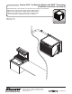
Horizon Elite™ Ice Machine Models with RIDE™ Technology Installation Instructions for Drop-In HCC/HCD710AJS, HCC1010AJS, HCC1410AJS, HCC1010WJS, HCC1410WJS, HMC1010AJS, HMC1410AJS, HMC1010WJS, HMC1410WJS, HCE1010AJS, HCE1410AJS, HCE1010WJS, HCE1410WJS HME1010AJS, HME1410AJS, HME1010WJS, HME1410WJS (See model number configurator on page 2 for details.) Order parts online www.follettice.com self-contained 801 Church Lane • Easton, PA 18040, USA Toll free (877) 612-5086 • +1 (610) 252-7301 www.follettice.
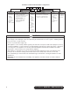
Chewblet® Ice Machine Model Number Configurations HC Icemaker MC Maestro™ Chewblet® (425 Series) HC Horizon Chewblet (710, 1010, 1410, 1810, 2110 Series) HM Horizon Micro Chewblet Voltage D 1810 A V Series 425 up to C 208-230/60/1 (icemaking head) Self-contained only. 425 lbs D 115/60/1 (icemaking head) (193 kg) Self-contained and remote. If remote 710 up to unit, high side is 208-230/60/1. 675 lbs E 230/50/1 (icemaking head) (306 kg) Self-contained only.
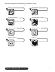
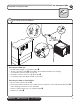
Read and complete the following 8 installation steps 1 3 5 7 Unpack Dispenser preparation Ice transport tube Internal connection DROP-IN • RIDE Technology self-contained 2 4 6 8 Site preparation Louvered docking assembly External connection Front cover 3
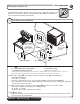
Carefully unpack and inspect the contents of your Follett ice machine. 1.
Site preparation Prepare the installation site. 2 Provide drainage, water supply and electrical power to within 6 feet (2m) of ice machine in accordance with local and national codes. Outdoor installation is not recommended and will void warranty. 2.1 2.1 Installation site requirements NEMA 6-15 H_E1010A/W ‡ requires 15 amp circuit 1.50 mm2 wire H_E1410A/W H_C1010A/W ➊ ‡ requires 20 amp circuit 4.00 mm2 wire ➋ ➌ 2 ft.
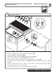
Dispenser preparation Prepare the dispenser. 2.1 3.1 3 Dispenser preparation Hot Water 160 F (71 C) ➌ ➍ 4" (101,6mm) 12" (304,8mm) min. ➐ ➋ ➊ ➒ ➎ ➏ ➓ ➐ ➑ Determine best route for ice transport tube run. Note: 12" (304,8mm) clearance is required.
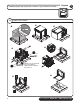
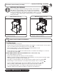
Install the louvered docking assembly. Louvered docking assembly 4 BEFORE PROCEEDING Prior to installing the louvered docking assembly, ensure that the drain fitting is oriented (right or left) correctly for your installation. An optional straight drain fitting is also supplied. You may need to remove the back panel of the docking assembly in order to re-orient or change the drain fitting. Replace back panel prior to mounting the docking assembly.
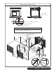
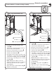
Undercounter installation detail Front View Top View Access panel/ door on counter 2" (51 mm) ➌ ➊ 2.25" (57 mm) ➍ 2" (51 mm) 24" x 15" cutout (610 mm x 381 mm) bottom of ice machine side of ice machine CAUTION • Keep ventilation openings in the appliance enclosure clear of obstruction. • To ensure proper ventilation (if not using supplied grille) carefully review air circulation specifications on facing page (4.1) 3D Counter View 31.25" min. (794 mm) 23.5" min. (597 mm) 24" min.
Ice transport tube Install the ice transport tube. 5.1 5 Ice transport tube installation. ➋ Hot Water 160 F (71 C) ➎ ➊ 1/4" ➌ 1' ➍ ➏ ➐ Ice transport tube tips • Insulate entire length of ice transport tube ➊ • Secure ice transport tube ➋ as needed to prevent dips and traps from forming. For long tube runs see guide on page 16. • Pitch tube at least 1/4" per foot (6,4mm/.
External connections Connect utilities to louvered docking assembly. 6.1 Air-cooled ice machines only 6.2 6 Water-cooled ice machines only ➊ ➊ ➏ ➋ ➋ ➐ ➌ Minimum 8" radius ➑ Minimum 8" radius ➏ ➌ 2 ft. x 1" OD silicone tubing 2 ft. x 1" OD silicone tubing 3/4" barb x 3/4" FPT 3/4" barb x 3/4" FPT ➍ 3/4" MPT x 1" slip 3/4" MPT x 1" slip ➎1" Stand pipe/Drain • Rough-in ice machine potable water supply ➊.
Connect louvered docking assembly to ice machine. Internal connections 7 CAUTION • Plug must be accessible after final installation. • H_E1410A/W 230/50/1) requires a 20 amp circuit (4.00 mm2 wire) Air-cooled ice machines – follow steps 7.1 through 7.5. 7.1 7.
Water-cooled ice machines – follow steps 7.6 through 7.12. 7.6 TDS switch Cooling lines CLEAN POWER ON HIGH LOW BIN MAKING ICE SLEEP CYCLE TIME DELAY LOW WATER MAINT/CLEAN SERVICE HIGH AMPS HIGH PRES TDS DRAIN CLOG CLEANER FULL 7.5 In LOW • Set the TDS switch on the electrical box: HIGH: for extended service life LOW: for low-scale water 7.7 • Install ice machine cooling water lines to louvered docking assembly 7.
7.9 7.10 Cooling lines and power Power cord ➋ ➊ • Remove twist tie • Carefully pass cord thru opening and plug into wall outlet • For H_E units, install a suitable plug • Connect cooling water lines to ice machine (Water "Out" connects to water regulator.) ➊ • Water valve is set at the factory. DO NOT remove seal or adjust water valve ➋ 7.
Front cover Install front cover to ice machine. 8 Install front cover Front cover installation – air-cooled undercounter only ➊ ➋ ➋ ➌ ➊ ➌ • Slide ice machine cover over machine ensuring that tabs on back of cover slip under louvers on back of louvered docking assembly ➊ • Insert and tighten two screws through cover and into louvered docking assembly CAUTION • Keep ventilation openings in the appliance enclosure clear of obstruction.
Long tube run recommendations max. 2 ft (.6m) ➋ ➊ 1/4" 1' • Pitch ice transport tube to allow melt water to drain towards ice machine ➊ • Secure insulated ice transport tube at least every 2 ft (.
801 Church Lane • Easton, PA 18040, USA Toll free (877) 612-5086 • +1 (610) 252-7301 www.follettice.