
Installation Instructions

7
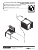
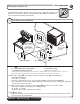
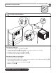
DROP-IN • RIDE Technology self-contained
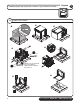
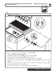
Install the louvered docking assembly.
Louvered docking assembly
4
DOCKING STATION
(See detail drawing on page 8)
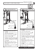
• Position and screw louvered docking assembly to the bottom of counter inside of access panel/
door 2" (51 mm) from the front edge of the cross brace
➊
• The mounting surface for the louvered docking assembly must be solid.
Do not mount directly onto runners or channels.
• There must be no lip or edge that would hinder the ice machine from sliding in or out of the
louvered docking station
➋
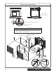
INTAKE AND EXHAUST GRILLE PLACEMENT: Air-cooled models only
(See detail drawing on page 9)
• Position the intake grille cut out in the access panel/door
Note: Ice machine must be aligned with cut out and inside of access panel to provide a tight
seal and prevent recirculation of hot exhaust air.
• Left edge of cutout should be 2.25" (57 mm) from the left side of the ice machine
➌
• Bottom edge of cutout should be 2" (51 mm) from the bottom of the ice machine
➍
• Position supplied exhaust grille at least 18" (458mm) away from intake grille
➎
.
Where possible, install exhaust grille to the rear or side of the base cabinet.
• If not using supplied grille, air circulation requirements below must be met:
250 sq. in (1613 sq cm) intake air, 250 sq. in (1613 sq. cm) exhaust air
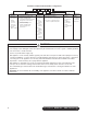
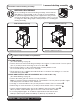
Undercounter installation requirements
4.1
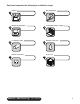
Wall bracket accessory Machine stand accessory
• Mount louvered docking assembly to wall
bracket accessory
• Mount louvered docking assembly to
machine stand accessory
Prior to installing the louvered docking assembly, ensure that the
drain tting is oriented (right or left) correctly for your installation.
An optional straight drain tting is also supplied. You may need to
remove the back panel of the docking assembly in order to re-orient
or change the drain tting. Replace back panel prior to mounting the
docking assembly.
BEFORE PROCEEDING