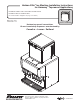
Horizon Elite™ Ice Machine Installation Instructions for Harmony™ Top-mount Applications HCD/HMD/HCF/HMF1010RHT, HCD/HMD/HCF/HMF1410RHT, HCD/HMD1010NHT, HCD/HMD1410NHT (See model number configurator on page 2 for details.) Order parts online www.follettice.com remote condensing Horizon top-mount ice machines fit most countertop dispensers manufactured by Cornelius • Lancer • SerVend 801 Church Lane • Easton, PA 18040, USA Toll free (877) 612-5086 • +1 (610) 252-7301 www.follettice.
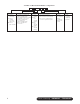
Chewblet® Ice Machine Model Number Configurations HC Icemaker MC Maestro™ Chewblet® (400 Series) HC Horizon Chewblet (1000, 1400, 1650 Series) HM Horizon Micro Chewblet 2 Voltage C 1400 A Series 400 up to C 208-230/60/1 (icemaking head) Self-contained only. 454 lbs D 115/60/1 (icemaking head) (206kg) Self-contained and remote. If remote 1000/1010 unit, high side is 208-230/60/1. up to E 230/50/1 (icemaking head) 1036 lbs Self-contained only.
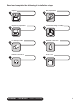
Read and complete the following 8 installation steps 1 3 5 7 Unpack 2 Dispenser preparation 4 Ice transport tube 6 Internal connection HARMONY • TOP-MOUNT 8 remote condensing Site preparation Louvered docking assembly External connection Front cover 3
Carefully unpack and inspect the contents of your Follett ice machine. 1.
Site preparation Prepare the installation site. 2 Provide drainage, water supply and electrical power to within 6 feet (2m) of ice machine in accordance with local and national codes. Outdoor installation of low side is not recommended and will void warranty. 2.1 2.
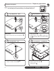
Dispenser preparation Prepare the dispenser. 3 Note: The instructions below only apply to 22" & 30" wide dispensers. 44" wide dispenser instructions may be found with the top kit. 3.1 3.2 Top preparation – ALL Top preparation – ALL ➊ ➊ ➌ ➊ ➊ ➋ All models • Remove protective tape from gaskets 3.3 ➊ • Apply gaskets ➊ • Install shuttle actuator ➋ through bottom of dispenser top and secure with locking nut ➌ 3.
3.5 3.6 Top preparation – LANCER Agitation adjust. – CORNELIUS ➊ ON OFF ➋ ➋ Lancer models only • Remove protective tape • Apply gaskets ➋ Adjust the agitation timer located on the Cornelius PC board to 1 second on, 1 hour off. Note: See Cornelius manual for more information. Agitation adjustments – LANCER 4500 SERIES PRESS IN ON THIS SIDE TO TURN SWITCH ON.
3.9 Agitation adjustments – LANCER FS SERIES Initialization Screen (Boot Up Only) Lancer FS-16 Ver. 0.
3.
3.12 Dispenser diverter plate installation – CORNELIUS ED, DF and DB SERIES GATE MOUNTING PLATE STORAGE HOPPER FLANGE EXTENDS INTO STORAGE HOPPER THROUGH GATE OPENING ICE DIVERTER ICE CHUTE COVER APPLY RTV TO THIS SURFACE TO SEAL TO HOPPER GATE MOUNTING PLATE 10-32 WASHER GASKET ICE CHUTE Cornelius ED, DF and10-32 DB NUT series only These dispensers require the installation of an ice diverter at the dispenser opening.
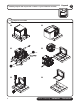
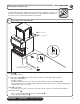
Louvered docking assembly Install the louvered docking assembly. 2.1 4.1 4 Louvered docking assembly 2" (50,8 mm) 1.88" (47,8 mm) ➋ ➊ 3/8˝ ∅ high pressure line 1" (25,4 mm) Stub Typ 3.
Ice transport tube 5 Install the ice transport tube. 5.
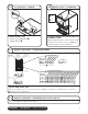
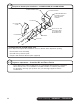
External connections Connect utilities to louvered docking assembly. 6.1 6.2 Water and drain ➋ 6 Refrigerant lines ➊ ➌ ➊ • Remove access panel if necessary. • Install drain line ➊. The rigid drain line from the ice machine must have at least 1/4" per foot pitch (6,4mm/0,3m). • Rough-in ice machine potable water supply ➋. 3/8" push-in connection will be made at shut-off valve inside machine. • Apply Petrogel to barbed drain fitting ➌ • Replace access panel.
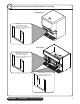
Internal connections Connect louvered docking assembly to ice machine. 7.1 Ice transport tube installation 7.2 7 Water line ➋ ➊ ➋ ➊ • Slide ice machine into louvered docking assembly ensuring that drain tube is fully seated on barbed drain fitting ➊ • Insert ice transport tube all the way into coupling and tighten nut firmly ➋ • Insert potable water line into valve 7.3 7.
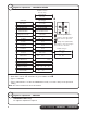
7.6 Power cord TDS switch CLEAN POWER ON HIGH LOW BIN MAKING ICE SLEEP CYCLE TIME DELAY LOW WATER MAINT/CLEAN SERVICE HIGH AMPS HIGH PRES TDS DRAIN CLOG CLEANER FULL 7.5 LOW • Set the TDS switch on the electrical box: HIGH: for extended service life LOW: for low-scale water • Position plate into opening and secure with supplied screw NOTICE Ice machine MUST be sanitized prior to operation! Consult Operation and Service Manual provided with ice machine for sanitizing instructions.
Front cover Install front cover to ice machine. 8.1 Install condensing unit 8.2 Install ice machine front cover ➋ • Complete installation of condensing unit or connection to rack system. • Required rack system capacity at 0 F (-18 C) evaporator (EPR supplied by installer).