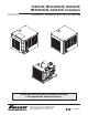
T400A/W, MCD400A/W, R400A/W, MFD400A/W, D400A/W Icemakers Order parts online www.follettice.com Installation, Operation and Service Manual Following installation, please forward this manual to the appropriate operations person. 801 Church Lane • Easton, PA 18040, USA Toll free (800) 523-9361 • (610) 252-7301 Fax (610) 250-0696 • www.follettice.
Follett Corporation Equipment Return Policy Follett equipment may be returned for credit under the following conditions: 1. The equipment is new and unused. 2. A return authorization number has been issued by customer service within 30 days after shipment. 3. Follett receives the equipment at the factory in Easton, PA within 30 days after issuance of the return authorization number. 4. The equipment must be returned in Follett packaging.
Table of contents Welcome to Follett Corporation Specifications Installation Top mount icemakers (models T400A/W, MCD400A/W and MFD400A/W) Satellite-fill icemakers (models MCD400A/W, R400A/W) Ventilation Ice transport tube Start up Operation Cleaning Weekly exterior care Monthly condenser cleaning Semi-annual evaporator cleaning Service Icemaker operation Technical specifications Refrigeration system diagram Refrigeration pressure data Compressor data Gearmotor data MCD400A/W wiring diagram Electrical contr
Welcome to Follett Follett equipment enjoys a well-deserved reputation for excellent performance, long-term reliability and outstanding after-the-sale support. To ensure that this equipment delivers that same degree of service, we ask that you review the installation portion of this manual before beginning to install the unit. Our instructions are designed to help you achieve a trouble-free installation.
Specifications Electrical Each icemaker and dispenser require a separate circuit with electrical disconnect within 10 ft (6m). Equipment ground required. Standard electrical – 115V, 60Hz, 1 phase. Maximum dispenser fuse – 15 amps, Maximum icemaker fuse – 20 amps each Maximum icemaker amperage – 11 amps each Cord and plug provided on icemaker and dispenser Electrical connections Model Electrical connection Circuits required 25FB400A/W, 50FB400A/W, 110FB400A/W cord & plug provided 115/60/1, 20 amp max.
Dimensions and clearances Entire front of icemaker must be clear of obstructions/connections to allow removal. 12" (305mm) clearance above icemaker for service. 6" (153mm) minimum clearance between exhaust side of icemaker and any adjacent equipment. MCD400A & R400A – 18" (457mm) minimum, 10 ft (3m) maximum clearance between discharge and air intake grilles. Front view — air-cooled top mount Back view — air-cooled top mount 13.00" (331mm) C 4.875" (124mm) 2.
Installation Icemaker performance is very sensitive to the quality of installation. To ensure proper performance, ease of service and warranty coverage, it is critical that you follow the requirements detailed in this manual. If you cannot meet these requirements or have questions, call our technical service group immediately at (800) 523-9361 or (610) 252-7301. Top mount icemaker on bin installation procedure (models MCD400A/WBT and MFD400A/WBT) Install icemaker and rough-in utilities 1.
After turning power on 1. Turn power to icemaker on and confirm that gearmotor, compressor and fan motor start immediately. 2. Check that ice begins to enter bin within approximately 10 minutes. 3. With icemaker running, check that float reservoir water level is approximately 3/8" (10mm) below internal overflow and adjust to this level (raised line on side of reservoir) if necessary. 4. After making ice for 10 minutes, put ice against ice level control stat cap tube and check that icemaker shuts down. 5.
Field wiring diagrams for Satellite-fill icemaker installations All field wiring must be installed in accordance with NEC and local electrical codes. Field wiring diagram is intended only to aid electrician or technician in understanding how equipment works. Should local codes require a hard-wired connection and/or shielded wiring, eliminate the cord and plug(s) and follow the appropriate field wiring diagram. MCD400A/W and R400A/W icemakers have separate power supply from dispenser.
Installing Satellite-fill icemaker and rough-in utilities with optional slide-out accessory The slide-out accessory allows the icemaker to be pulled out on a track from below a counter without disconnecting utilities. A leg supports the icemaker in the full-out position. If your order did not include a slide-out accessory proceed to icemaker ventilation and exhaust.
Step 2 – Installing Satellite-fill icemaker on slide-out track A. When icemaker is shipped with slide-out track accessory (follow either A or B) 1. 2. 3. 4. Connect inlet water, drain, and power supply to back of vertical utility panel. Place icemaker on slide-out track assembly. Connect drain and water lines. Connect electrical plugs from icemaker to utility panel. B. When icemaker is installed in and shipped with counter 1. 2. 3. 4. 5. 6. 7. 8.
Front view 3/8" OD push-in condenser inlet (water-cooled only) 5.25" (134mm) icemaker power outlet 3/8" OD push-in condenser drain (water-cooled only) icemaker twist-lock bin signal cord 3/8" OD push-in icemaker water inlet barbed push-on icemaker drain 25.
Satellite-fill icemaker ventilation and exhaust requirements Fabricator-supplied, custom air intake grilles must have 12" x 12" (305mm x 305mm) opening yielding 100 sq. inches (645 sq. cm) of open air space within duct perimeter. Block off any open area outside of the air duct. Intake air requirements — air-cooled icemakers (MCD400AHS, MCD400AVS & R400A only) 1. Check that 2" (51mm) duct is installed on condenser front. 2. Cut a 12" x 12" (305mm x 305mm) opening in counter face to align with duct. 3.
Satellite-fill icemaker ice transport tube installation Incorrect ice transport tube installation can result in wet ice and dispensing problems. Follow guidelines below to ensure correct installation. Call factory for assistance if you are unable to meet these requirements. General requirements Maximum length of tube run – 20 ft (6m). Factory approval required for longer runs. Run tube without dips. One continuous length of tube; no splices. Minimum radius of bends in tube – 6" (153mm) inside radius.
Additional ice transport tube connection specifications for Vision series ice and beverage dispensers Check to make sure bin signal on icemaker control board is switched to 24 volt connection. 1. Push one end of ice transport tube(s) through hole(s) provided in side of dispenser. 2. Route tube into ice tube bracket inside dispenser and engage bracket tabs in holes located in end of ice transport tube(s) (see drawings below). 3. Verify bin thermostat capillary tube is mounted correctly (see drawings below).
Ice transport tube installation detail install insulation on full run of tube Dispenser Evaporator grommet install clamp behind lip on evaporator port Satellite-fill icemaker start up procedure The start-up procedure below is intended to ensure that icemaker is operating properly after installation has been made. Check each item listed and call factory immediately for assistance if you experience problems with unit. Before turning on power 1. Turn on water to icemaker. 2.
Monthly condenser cleaning (air-cooled icemaker only) 1. Use a vacuum cleaner or stiff brush to carefully clean condenser coils of air-cooled icemakers to ensure optimal performance. 2. When reinstalling counter panels in front of remote icemakers, be sure that ventilation louvers line up with condenser air duct. Semi-annual evaporator cleaning (every 6 months) Fig. 5 Solution A – Ice machine cleaner: Prepare one gallon (3.8L) of Follett 2 SafeCLEAN™ Ice Machine Cleaner (one 7 oz packet) or equivalent.
Service Icemaker Operation (all models) Follett’s icemaker consists of four distinct functional systems: • Refrigeration system • Water system • Harvesting system • Electrical control system These four systems work together to accomplish the production and harvesting of ice. A problem in any one of these systems will result in improper operation of the entire ice production cycle.
Technical specifications (all models) Refrigeration system diagram high pressure switch high side service port condenser low side service port filter dryer compressor evaporator high pressure vapor thermostatic expansion valve high pressure liquid low pressure liquid low pressure vapor Refrigeration pressure data Water regulating valve is factory set at 225 PSIG head pressure. Readings within 10% of above table values should be considered normal.
Water-cooled icemaker capacity/24 hrs. Air-cooled icemaker capacity/24 hrs. Performance with new RG Group 1/2 ton coil (Note: Data expressed in lbs/hr and kg/hr) F C 50 10 60 16 70 21 80 27 90 32 60 16 510 232 482 219 454 206 424 193 394 179 70 21 454 206 435 198 417 190 385 175 354 161 Ambient Air Temperature ˚F/˚C 80 27 397 180 389 177 380 173 347 158 313 142 90 32 335 152 329 150 323 147 297 135 270 123 100 38 273 124 270 123 266 121 247 112 227 103 lbs. kg. lbs. kg. lbs. kg. lbs. kg. lbs. kg.
Electrical control system operation The D400A/W, MCD400A/WVS and R400A/W wiring diagrams which follow illustrate the circuitry of Follett icemakers used with ice dispensers. Both normal operation of the icemaker (Stages 1 - 6) and non-normal diagnostic sequences showing torque-out (Stages 7 - 10) for use in troubleshooting icemaker problems are shown. Follett icemakers used on top of an ice storage bin have a slightly different circuitry.
Normal operation – Stage 2 The water sensor verifies water in the float. The Water OK LED (WTR) comes on. At the same time, the gearmotor, compressor, and condenser fan motor come on, lighting the Drive LED (DR) and compressor LED (C). The compressor is started through a current style relay that is pulled in by the initial high current draw of the compressor. The gearmotor start windings are also energized through a current relay. The B-E and WTR LED remain on.
Normal operation – Stage 4 Once the ice level control opens, the B-E LED goes out. After a 10 second delay the LED (C), compressor, and fan motor go off and the B-T LED comes on. (Should the ice level control not remain open for 10 seconds, the icemaker will continue to run.) The gearmotor continues to run for 60 seconds. The purpose of this function is to drive the remaining ice out of the evaporator and to boil off any refrigerant remaining in the evaporator.
Normal operation – Stage 6 When the dwell time of 20 minutes has expired, the B-T LED goes off. The icemaker will go through the normal start-up sequence when the bin level control signals the control board for ice. The WTR LED will remain on as long as the water sensor in the float reservoir senses water.
Diagnostic sequence – Stage 8 If the restart is successful the 20M LED goes off, the 60 minute timer LED (60M) comes on. The 60M LED will remain on for 60 minutes from restart. A lighted 60M LED tells the technician that the icemaker has experienced an over-torque condition. If the icemaker runs without problems for 60 minutes and no additional torque errors occur, the 60M LED will go off and the icemaker will continue normal operation.
Diagnostic sequence – Stage 10 If the water level in the float reservoir drops to an unacceptable level, the WTR LED will go out, shutting the icemaker off. Also, the BT LED will come on, preventing the icemaker from restarting for twenty minutes. If water is restored, the WTR LED will come back on and flash to alert the technician that water to icemaker has been lost. The icemaker will then restart at the end of the 20 minute time delay. The flashing WTR LED can be cleared by pressing the reset button.
Refrigeration system (all models) All service on refrigeration systems must be performed in accordance with all federal, state and local laws. It is the responsibility of the technician to ensure that these requirements are met. Recharging icemaker to other than factory specifications will void the warranty.
Service procedures Fig. 7 Evaporator disassembly (Fig. 7) 1. 2. 3. 4. 5. 6. 7. 8. 9. 10. 11. 12. 13. 14. 15. Disconnect power to icemaker. Shut off water to icemaker. Drain evaporator and float tank. Disconnect plastic tubing from evaporator water inlet, drain pan stub, compression nozzle tubing and reservoir overflow tubing from secured clip. Disconnect ice transport tube from compression nozzle. Note: No compression nozzle on MFD400 series flake icemakers.
Troubleshooting chart Flashing water LED at any time indicates that water signal to board had been lost for more than one second. Ten-second delay: There is a 10 second delay in reaction to loss of water (WTR) or bin (B-E) signals. If signals are not lost for more than 10 seconds, no reaction will occur. Problem 1. Icemaker will not run. System status: compressor, gearmotor, and fan motor inoperative. 2. Compressor will not run. System status: gearmotor and fan motor run. 3. Unit cycles intermittently.
Troubleshooting Problem 6. Icemaker runs for short period of time and shuts down on torque error. System status: 20M or 2nd LED are lit. 7. Evaporator is iced up on the outside. No ice production. Indicators/possible cause 1. Kink in ice transport tube. 2. Bin level control remains in closed position. 3. Ice transport tube ruptured internally. 4. Worn evaporator bearings. 5. Faulty gearmotor start relay. Icemaker torques out within 5 seconds of start-up. 6.
Order parts online www.follettice.
Order parts online www.follettice.
Order parts online www.follettice.
Order parts online www.follettice.
Order parts online www.follettice.
Order parts online www.follettice.com Electrical components 1 2 3 4 POWER EARTH L1 L1 RESET I.D. LABEL L2 L2 L2 L2 L2 WATER PROBE DR C 20M 60M 2ND WTR B-T B-E SOFTWARE I.D. COMP. SWITCH LINE VAC FAN DRIVE COMM. 24 VAC COMP.
Order parts online www.follettice.
Order parts online www.follettice.
801 Church Lane • Easton, PA 18040, USA Toll free (800) 523-9361 • (610) 252-7301 Fax (610) 250-0696 • www.follettice.