Maestro Plus™ Ice Machine with RIDE™ Technology Installation Instructions for Harmony™ MCD425A/W HS, MCE425A HS, MCC425A HS (See model number configurator on page 2 for details.) Order parts online www.follettice.com self-contained Maestro Plus ice machines with RIDE technology fit most countertop dispensers manufactured by Cornelius • Lancer • SerVend 801 Church Lane • Easton, PA 18040, USA Toll free (877) 612-5086 • +1 (610) 252-7301 www.follettice.
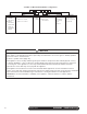
Chewblet® Ice Machine Model Number Configurations MC Machine MC Maestro Plus Chewblet (425 Series) MF Maestro Plus™Flake P Replacement R Symphony Pus RIDE Ice Machine Voltage C 425 Series C 208-230/60/1 Self-contained D 115/60/1 Self-contained E 230/50/1 Self-contained A V S Application Condenser 425 up to A Air-cooled, self-contained 454 lbs W Water-cooled, (206kg) self-contained V Vision™ Configuration S RIDE® (RIDE remote ice delivery equipment) H Harmony™ B Ice storage bin J T Top-mou
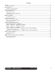
Contents Unpack............................................................................................................................................................................4 Unpack Ice Machine..................................................................................................................................................4 Site Preparation.............................................................................................................................................
1. Unpack Carefully unpack and inspect the contents of your Follett ice machine. 1.
2. Site Preparation Provide drainage, potable water supply and electrical power to within 6 feet (2m) of ice machine in accordance with local and national codes. Outdoor installation is not recommended and will void warranty. 2.1 Installation site requirements 115 V ➊ ➋ NEMA 5-15 ➌ ➍ ➍ 1/4" 115 V ±5% 230 V ±10% 220 V ±10% 1' Electrical ➊ WARNING! §§ This appliance should be connected by a qualified person in accordance with application codes.
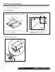
3. Dispenser Top Preparation Prepare the dispenser. Note: The instructions below only apply to 22” & 30” wide dispensers. 44” wide dispenser instructions may be found with the top kit. 3.1 Top Preparation Standard (Cornelius, Lancer, or Servend) Lancer Sensation and Touchpoint 5" (127 mm) Back of Top 9.00" 10.00" 3.0" ∅ (77,2 mm) 3.0" ∅ Front of Top Locate hole position 5" (127 mm) from back of dispenser top.
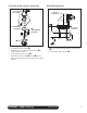
3.3 Install shuttle actuator and bracket 3.4 Route thermostat SHUTTLE ➌ ACTUATOR SHUTTLE ACTUATOR ➋ 1 ➊ THERMOSTAT GROMMET 3/4" RADIUS (APPROX.) ➍ THERMOSTAT BRACKET 2 ➋ ➎ NUT §§ Install thermostat grommet ➊. §§ Remove protective tape and apply gaskets ➋ to shuttle actuator and nut. §§ Place shuttle actuator in hole ➌. §§ Install thermostat bracket ➍ and nut ➎. Ensure that nut captures the thermostat bracket, then hand tighten.
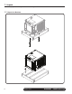
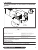
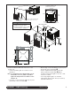
4. Mount Ice Machine Mounting options: Cabinet, Wall, Stand In cabinet Wall bracket Stand 18.125" (46.0 cm) 26.25" (66.7 cm) 20.125" (51.1 cm) 6.80" (17.27 cm) B A C D A - 15.125" (38.4 cm), C - 13.25" (33.6 cm) B - 18.625" (47.3 cm) D - 20.75" (52.7 cm) 4.1 Ice machine in cabinet Maestro ice machines can be installed undercounter/in-cabinet to fill bins or dispensers using RIDE technology. Care must be taken to ensure proper cabinet venting to avoid recirculation of hot air.
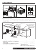
Completed installation with gasket and door in place air intake gasket cabinet door Side View door & gasket must mate directly A 22.75" (57.8 cm) 29" (74 cm) minimum Front supplied air intake grille cutout for supplied air intake grille 12"W x 12"H (30 cm x 30 cm) drain tube A: additional 3" (7.6 cm) required if receptacle located directly behind unit. WARNING • Keep ventilation openings in the appliance enclosure clear of obstruction. Failure to do so could result in damage to equipment.
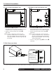
Front View - Air Cooled 5. External Connections 5.1 Air-cooled ice machines only 5.2 Water-cooled ice machines only CONDENSER OUTLET ➋ ➌ ➍ ➋ ➊ ➊ §§ Install drain line ➊ (3/4" MPT). The rigid drain line from the ice machine must have Front Air Cooled at least 1/4" per footView (6,4 -mm/0,3 m) pitch. §§ Install ice machine potable water supply ➋ (3/8" FPT).
6. Dispenser Agitation Adjustment 6.1 Agitation adjustments - CORNELIUS ON OFF Cornelius models ED, DB, DF, IDC and Flavor Fusion §§ Adjust the agitation tier located on the Cornelius PC board to 1 second on, 1 hour off. Note: see Cornelius manual for more information. 6.2 Agitation adjustments – LANCER 4500 SERIES AGITATION TIME 3 X = ON O = OFF 4 S S S 1 2 3 4 4 SWITCH NUMBER S 1 PRESS IN ON THIS SIDE TO TURN SWITCH ON.
6.4 Agitation adjustments – LANCER FS SERIES Initialization Screen (Boot Up Only) Lancer FS-16 Ver. 0.
6.
6.
7. Transport tube installation Incorrect ice transport tube installation can result in wet ice and dispensing problems. Follow guidelines below to ensure correct installation. Call factory for assistance if you are unable to meet these requirements. 7.1 General requirements §§ §§ §§ §§ §§ §§ Maximum length of tube run – 20 ft (6 m). Factory approval required for longer runs. Run tube without dips. One continuous length of tube; no splices. Minimum radius of bends in tube – 6" (15.3 cm) inside radius.
8. RIDE model ice machine start up procedure The start-up procedure below is intended to ensure that ice machine is operating properly after installation has been made. Check each item listed and call factory immediately for assistance if you experience problems with unit. NOTICE! §§ Ice machine MUST be sanitized prior to operation! §§ Consult Operation and Service Manual provided with ice machine for sanitizing instructions. 8.1 Before turning on power 1. Turn on water to ice machine. 2.