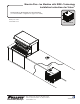
Maestro Plus™ Ice Machine with RIDE™ Technology Installation Instructions for Vision™ MCD425A/W VS, MCE425A/W VS, MCC425A/WVS (See model number configurator on page 2 for details.) Order parts online www.follettice.com self-contained 801 Church Lane • Easton, PA 18040, USA Toll free (877) 612-5086 • +1 (610) 252-7301 www.follettice.
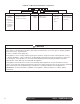
Chewblet® Ice Machine Model Number Configurations MC Machine MC Maestro Plus Chewblet (425 Series) MF Maestro Plus™Flake P Replacement R Symphony Pus RIDE Ice Machine Voltage C 425 Series C 208-230/60/1 Self-contained D 115/60/1 Self-contained E 230/50/1 Self-contained A V S Application Condenser 425 up to A Air-cooled, self-contained 454 lbs W Water-cooled, (206kg) self-contained V Vision™ Configuration S RIDE® (RIDE remote ice delivery equipment) H Harmony™ B Ice storage bin J T Top-mou
Contents Unpack..............................................................................................................................................................................4 Unpack Ice Machine....................................................................................................................................................4 Site Preparation.........................................................................................................................................
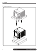
1. Unpack Carefully unpack and inspect the contents of your Follett ice machine. 1.
2. Site Preparation Provide drainage, potable water supply and electrical power to within 6 feet (2m) of ice machine in accordance with local and national codes. Outdoor installation is not recommended and will void warranty. 2.1 Installation site requirements 115 V ➊ ➋ NEMA 5-15 ➌ ➍ 1/4" Electrical 1' ➍ 115 V ±5% 230 V ±10% 220 V ±10% ➊ WARNING! §§ This appliance should be connected by a qualified person in accordance with application codes.
3. Dispenser Preparation 3.1 Install Vision dispenser Refer to Vision Installation, Operation and Service Manual packaged with dispenser for detailed instructions. 3.2 Install bin signal ➋ Ground ➊ Relay in electrical box converts 24 V to contact closure 1. Mount the electrical box to the side of the Vision dispenser ➊ to establish a ground connection. Note: If a 2 x 4 box is mounted to a non-grounded surface, connect ground wire at an appropriate ground. 2.
3.3 Install transport tube Correct installation Incorrect installation §§ Length of run no more than 20 ft (6 m) §§ Tube run continuously from ice machine to dispenser §§ Insulation on entire run of tube §§ No dips or tight bends §§ Tube secured in place §§ No splices §§ Dips in tube where water can collect §§ Splice or tight bend that restricts ice flow §§ Uninsulated tube that results in wet ice and potential dispensing problems 3.3.
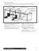
Bin thermostat capillary tube mounting Bin thermostat capillary tube mounting Front View, VU155 Front View, VU300 ice tube retaining bracket thermostat thermostat ice tube retaining bracket ice tube tabs in ice tube retainer bracket engage holes in ice tube and hold tube in place ice tube thermostat 4. Mount Ice Machine Mounting options: Cabinet, Wall, Stand In cabinet Wall bracket Stand 18.125" (46.0 cm) 26.25" (66.7 cm) 20.125" (51.1 cm) 6.80" (17.27 cm) B A C D A - 15.125" (38.
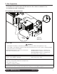
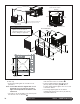
4.1 Ice machine in cabinet Maestro ice machines can be installed undercounter/in-cabinet to fill bins or dispensers using RIDE technology. Care must be taken to ensure proper cabinet venting to avoid recirculation of hot air. Improper venting can cause ice machine outages. Supplied grilles 18.00" (45.7 cm) minimum Maestro ice machine Ice transport tube minimum 1/4" per foot (2 cm per meter) pitch toward ice machine secure to prevent dips and traps from forming 22.75" (57.8 cm) minimum 24.50" (62.
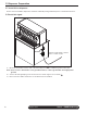
Completed installation with gasket and door in place air intake gasket cabinet door Side View door & gasket must mate directly A 22.75" (57.8 cm) 29" (74 cm) minimum Front supplied air intake grille cutout for supplied air intake grille 12"W x 12"H (30 cm x 30 cm) drain tube A: additional 3" (7.6 cm) required if receptacle located directly behind unit. WARNING • Keep ventilation openings in the appliance enclosure clear of obstruction. Failure to do so could result in damage to equipment.
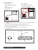
Front View - Air Cooled 5. External Connections 5.1 Air-cooled ice machines only 5.2 Water-cooled ice machines only CONDENSER OUTLET ➋ ➌ ➋ ➍ ➊ ➊ §§ Install drain line ➊ (3/4" MPT). The rigid drain line from the ice machine must have Front Air Cooled at least 1/4" per footView (6,4 -mm/0,3 m) pitch. §§ Install ice machine potable water supply ➋ (3/8" FPT).
6. Transport tube installation Incorrect ice transport tube installation can result in wet ice and dispensing problems. Follow guidelines below to ensure correct installation. Call factory for assistance if you are unable to meet these requirements. 6.1 General requirements §§ §§ §§ §§ §§ §§ Maximum length of tube run – 20 ft (6 m). Factory approval required for longer runs. Run tube without dips. One continuous length of tube; no splices. Minimum radius of bends in tube – 6" (15.3 cm) inside radius.
7. RIDE model ice machine start up procedure The start-up procedure below is intended to ensure that ice machine is operating properly after installation has been made. Check each item listed and call factory immediately for assistance if you experience problems with unit. NOTICE! §§ Ice machine MUST be sanitized prior to operation! §§ Consult Operation and Service Manual provided with ice machine for sanitizing instructions. 7.1 Before turning on power 1. Turn on water to ice machine. 2.
Maestro Plus Vision • RIDE Technology
Vision • RIDE Technology Maestro Plus 15
Maestro Plus and Harmony are trademarks of Follett LLC. Follett, Chewblet and RIDE are registered trademarks of Follett LLC, registered in the US. 801 Church Lane • Easton, PA 18040, USA Toll free (877) 612-5086 • +1 (610) 252-7301 www.follettice.