REF Series Undercounter Refrigerator Order parts online www.follettice.com Installation, Operation and Service Manual Service numbers B59000 and above Following installation, please forward this manual to the appropriate operations person. 801 Church Lane • Easton, PA 18040, USA Toll free (800) 523-9361 • (610) 252-7301 Fax (610) 250-0696 • www.follettice.
Table of contents Welcome to Follett Before you begin 3 3 Specifications 3 Installation procedures Installing legs Installing shelves Installing controller faceplate Changing controller settings Reversing door 4 4 4 4 4 5 Controller Controller operation Programming the controller 6 6 6 Operation How the refrigerator works Temperature control Defrosting Cleaning 10 10 10 10 10 Service information Latch adjustment Gasket replacement Slide-out compressor tray Controller replacement Wiring diagram Ref
Welcome to Follett Follett equipment enjoys a well-deserved reputation for excellent performance, long-term reliability and outstanding after-the-sale support. To ensure that this product delivers that same degree of service, we ask that you take a moment to review this manual before beginning the installation. Should you have any questions or require technical help at any point, please call our technical service group at (800) 523-9361 or (610) 252-7301.
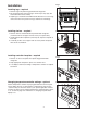
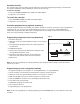
Fig. 1 Installation Installing legs – required 1. Remove legs from plastic bag packed inside refrigerator. 2. Tip refrigerator back and screw legs in all the way to stop (they will extend 1/8" below base of REF). 3. Adjust legs as needed to level REF in both directions. To access legs, remove the lower front panel. Turn legs clockwise to extend legs. Installing shelves – required Fig. 2 1. Remove shelves and shelf brackets packed inside refrigerator.
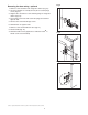
Reversing the door swing – optional Fig. 5 1. Remove screws and latch from refrigerator cabinet. (Fig. 5.1). 2. Use flat screwdriver to carefully remove (do not scratch) hinge covers (Fig. 6.1). 3. Support door and remove screws attaching hinge to refrigerator cabinet (Fig. 6.2). 4. Cover hinge screw holes with screw hole plugs removed from opposite side. 1 5. Reverse door and reinstall hinge screws. 6. Reinstall latch on opposite side. 2 7. Remove screws and handle from door (Fig. 7.1). 8.
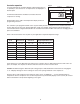
Fig. 8 Controller operation In normal operation the controller displays cabinet temperatures in °F (default) or user-selected °C. °C temperatures are displayed to 1 decimal point. An LED located below the snowflake icon flashes when the compressor is running. UP arrow rocker button * 38 Rocker buttons to the right of the temperature display control all programming functions.
To display temperature cut-out STEP 1 INPUT Press and release SET DISPLAY Current cut-out temperature will display for approximately 5 seconds.
To change temperature display from °C to °F If you have programmed your controller to display in °C and want to change it back to display in °F, follow the steps below.
Controller security The controller panel can be locked to prevent inadvertent or intentional programming changes. In locked mode, the controller will display cabinet temperature and cut-out set point only. To lock the controller 1. Press the UP/DOWN ARROW in the middle until “POF” displays. 2. Programmer is now locked. To unlock the controller 1. Press UP/DOWN ARROW in middle until “PON” displays. 2. Programmer is now unlocked.
Operation The temperature control board and probe indicate when the refrigeration system is required to turn on and off. The refrigeration system removes heat from the cabinet interior and rejects it to the surrounding room air. When the cabinet interior temperature reaches 4°F above the controller set point, the probe signals the controller to turn the refrigeration system on. The normally open controller contacts close and energize the evaporator and condenser fan motors and compressor.
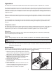
Service Fig. 11 Latch adjustment To adjust for proper latch engagement 1. Loosen striker plate mounting screws (Fig. 11.1). 2. Move striker plate up or down as required and tighten screws. 3. Test operation of latch. To adjust for proper gasket seal 1. Loosen striker depth adjustment screw (Fig. 11.2). 2. Adjust stop in or out and tighten screws. 1 3. Test operation of latch. 2 Door gasket replacement 1. Remove existing gasket from mounting track. 2.
Controller replacement 1. Disconnect power to unit: a. Push front panel rocker switch to OFF position. b. Switch circuit breaker to OFF position and disconnect power cord. 2. Remove 4 screws from front panel to access back of controller. 3. Disconnect front panel wiring harness from refrigerator at 5 pin connector. 4. Disconnect wiring from controller back. 5. Push in at center of orange* brackets to release and slide brackets back and off of controller. 6. Push controller out through front of front panel.
Refrigeration system The REF Series refrigeration system is designed to give many years of trouble-free service. Except for routine cleaning of the air-cooled condenser and related parts, the refrigeration system requires no service or maintenance. The system uses a capillary tube and is critically charged. Access fittings are provided for ease of service. However, the connection of refrigeration service hoses to the fittings will almost invariably result in a significant change in the system charge.
Refrigerator troubleshooting guide Before calling for service 1. Check that unit is plugged in. 2. Test outlet with another appliance to verify power. Symptom Possible cause Solution Refrigerator does not operate (no components run). 1. Power switch faulty or in OFF position; loose connection. 2. Refrigerator not plugged in. 3. No power to cord. 4. Temp controller not energizing components. 5. Probe not sensing cut in temperature. 1. Turn power switch to ON position; check switch and connections. 2.
Accessories Temperature alarm Fig. 13 Before installing alarm OFF 1. Remove supplied 9-volt back-up battery from packing box. OFF 2. Remove 2 screws from module face and remove faceplate. OFF OFF 3. Install back-up battery on battery connector. 4. Locate DIP switches on the back of the faceplate (Fig. 13). 5. Review the factory DIP switch settings (Fig. 14) and make any changes required to meet the needs of your specific application. POWER SENSOR OUTPUT 6. Reinstall faceplate. Fig.
Setting alarm temperatures Fig. 17 1. After the installation is complete, allow 30 minutes for the system to stabilize to ambient temperature. 2. Calibrate temperature alarm to refrigerator display a. Calibration is best done with the alarm probe removed from the probe bottle and placed in the vicinity of the temperature controller probe. Allow at least 15 minutes for the probe temperature to stabilize. b.
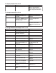
Replacement parts Condensing unit - Reference #11 Evaporator - Reference #5 14 2 3 10 1 9 8 13 6 12 7 4 15 Refrigeration Reference # 1 2 3 4 5 6 7 8 Not shown Not shown 9 10 Not shown 11 12 13 Not shown 14 15 Description Fan motor, evaporator Bracket, fan motor Fan blade Fan guard Evaporator (includes parts above) Filter drier & capillary tube Compressor Starting capacitor Starting relay Overload protector Condenser fan motor Condenser fan blade Fan motor bracket Condensing unit Wiring strain relief
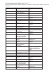
21 19 4 9 10 7 2 11 1 18 8 3 rear cutaway 17 12 6 13 5 16 20 22 14 15 Hardware Reference # 1 Not shown 2 3 4 5 6 7 Not shown 8 Not shown 9 Not shown 10 Not shown 11 12 13 14 15 16 Not shown 17 Not shown 18 Not shown 19 Description Door, REF5 (includes gasket – 21 3/8" x 21 3/8") Door, REF4-ADA (includes gasket – 21 3/8" x 18 5/8") Latch & striker (includes screws) Latch screws (each – 3 per latch) Striker screws (each – 2 per striker) Hinge (each – 2 required, includes screws) Hinge screws (e
Electrical components 20 Not shown 21 22 Not shown Not shown Not shown Not shown Not shown Temperature controller (includes 00130096) Probe, temperature Power cord Power switch, recessed mount Strain relief, wiring, front panel Faceplate, °F Faceplate, °C Programming key °F Programming key °C 00128868 00130096 00103903 00114371 00105577 00129403 00129411 00130112 00131722 Bottle kit (includes bottle, bracket and gasket) Controller kit (includes battery, probe and power supply) Gasket, bottle Bracket, bot
801 Church Lane • Easton, PA 18040, USA Toll free (800) 523-9361 • (610) 252-7301 Fax (610) 250-0696 • www.follettice.