VU155 Series Ice and Beverage Dispensers Order parts online www.follettice.com Installation, Operation and Service Manual Service numbers above B50000 Following installation, please forward this manual to the appropriate operations person. 801 Church Lane • Easton, PA 18040, USA Toll free (877) 612-5086 • +1 (610) 252-7301 www.follettice.
Table of contents Welcome to Follett Corporation Important cautions Specifications Installation Installing dispenser in counter Field wiring diagrams Installing optional ice machine Connecting beverage lines Operation How the dispenser works Cleaning Service Dispense chute cover removal Auger motor assembly removal Gate assembly removal Auger and auger tube removal Dispenser wheel removal Wiring diagrams Troubleshooting Replacement parts 3 3 4 6 6 7 7 8 8 8 9 11 11 11 11 11 11 12 13 15 2
Welcome to Follett Follett equipment enjoys a well-deserved reputation for excellent performance, long-term reliability and outstanding after-the-sale support. To ensure that this dispenser delivers that same degree of service, we ask that you take a moment to review this manual before beginning the installation of the dispenser. Should you have any questions or require technical help at any point, please call our technical service group at (877) 612-5806 or +1 (610) 252-7301.
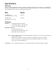
Specifications Electrical Each ice machine and dispenser require a separate circuit with electrical disconnect within 10 ft (6 m). Equipment ground required. Standard electrical – 115V, 60Hz, 1 phase. Maximum dispenser fuse – 15 amps. For ice machine circuit requirements, refer to the ice machine specification sheet. Model number Dispenser amperage VU155M series (no integral beverage cooling) 2.4 amps VU155B series (integral beverage cooling) 4.
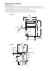
Dimensions and clearances Required clearances 51" (1295 mm) minimum above counter for installation if dispenser will be dropped into counter 36" (915 mm) minimum above counter for all units after installation for auger cleaning and servicing 12" (305 mm) minimum on side opposite ice chute for service 12" (305 mm) minimum on ice chute side if ice transport tube enters this side 12" (305 mm) minimum between dispenser side(s) and optional ice machine(s) Front View 37.25" (947mm) (10 valve unit) 31.
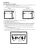
Installation Installing dispenser in counter Note: 1. All dispensers must be supported from below with supplied 6" – 9" (153 – 229 mm) adjustable leg accessory, or equivalent. Do not hang dispenser on flange. All dispensers must be installed level in both directions to ensure proper operation. Check that dispenser location meets all requirements in this manual and cut counter as shown. Plan View units with 10 valves counter cut-out Plan View units with up to 8 valves counter cut-out 30.
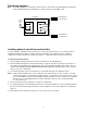
Field wiring diagrams Note: Field wiring diagrams are intended to aid electricians or technicians in understanding how equipment works. All field wiring must be installed in accordance with all local and NEC codes.
Connecting beverage lines 1. Connect syrup and water lines. Non-carbonated water line will be labeled “water”. Syrup lines are numbered and correspond to the valves as shown in drawing(s) below. Valve one is always next to ice tower. 2. The center 4 valves are pre-plumbed to both carbonated and non-carbonated water lines with the QuickCARB™ beverage manifold. Valves can be individually changed from a carbonated to a non-carbonated flavor with the flip of a lever (see below). 3.
Cleaning Using solutions below, clean and sanitize storage area and beverage lines before starting unit and on a routine basis as noted below. Note: Always disconnect power before cleaning dispenser. Do not run plastic parts through a dishwasher. Solution A: Combine 1 oz (30 ml) bleach with 2 gal (8 L) hot water. Solution B: Combine 1/4 oz (7 ml) bleach with 2 gal (8 L) hot water.
Recommended daily dispenser cleaning 1. Remove all debris from drain pan. 2. Pour 1 gallon (4 L) hot water into drain pan to keep drain lines clear. Recommended weekly dispenser cleaning 1. Remove drain pan and grille and wash with Solution A. Rinse thoroughly. 2. Remove nozzles and diffusers from valves, soak for at least 10 minutes in cleaning Solution A, rinse, sanitize with Solution B and reinstall. 3. Pour a solution of one cup (8 oz/237 ml) household bleach mixed with one gallon (3.
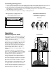
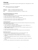
Service Front View right hand (RH), 8-valve unit Fig. 1 Dispense chute cover removal 1. Remove top cover. top cover chute cover valves 2. Push chute cover up vertically to slip off holding tab. 3. After clearing tab, pull chute cover forward to remove. drain pan assembly dispense chute Auger motor assembly removal 1. Remove top cover. 2. Remove one thumbnut on rear of motor bracket. 3. Lift motor bracket and motor up, unplug electric quick disconnects and remove. Fig.
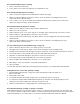
Wiring diagram FOR LEFT HAND MACHINE FOR RIGHT HAND MACHINE BLACK PL1-2 ORANGE NO C NO C NO R1 4 BLK LID BLK M1 7 DRAIN REAR LID PAN SWITCH SWITCH RED RED WHEEL MOTOR COUNTERCLOCKWISE ROTATION PURPLE ORANGE RED AUTOFILL R2 PURPLE 1 7 AUTOFILL R2 ORANGE 6 9 RED WHEEL MOTOR CLOCKWISE ROTATION RED RED PL3-2 M2 BLK WHT PL3-3 PL3-1 BLUE BLUE BATHPUMP MOTOR READY PL5-1 GRAY PL2-3 AUTOFILL PL3-3 BLK WHT M1 YLW WHT WHT WHITE L2 MTR BLK UE BL PL3-2 AUTOFILL R2 RED PURPLE RED
Dispenser troubleshooting guide Before calling for service 1. Check that ice is in the dispenser and that congealed cubes are not causing a jam. 2. Check that circuit breaker and switches are in ON position. 3. Check that drain pan, rear lid and top are on securely. If ajar, dispenser will not operate. When the top is off, auger does not operate, even though the solenoids do (page 14). 4. Check that all drains are clear.
Operational Status The chart below shows the operational status of various parts when certain switches are turned off or accessories are removed.
Replacement parts Order parts online www.follettice.
Order parts online www.follettice.com Dispense assembly Side View (RH unit with bath shown) 6 10 10 1 4 8 Top View 1 10 3 10 7 7 8 2 2 12 5 12 11 9 11 5 Reference # Description Part 1 Gate, dispense 502455 2 Linkage pin, gate/solenoid 502456 3 Pin, quick release, 3" (77 mm), bath gate and lever 501949 4 Pin, quick release, 5.
Order parts online www.follettice.
Order parts online www.follettice.
Order parts online www.follettice.
Electrical components 24VAC (YEL) NC 24VAC (RED) NO C PUMP 3 LID 5 1 L2 (WHT) 5 Top View Order parts online www.follettice.com MTR circuit board 2 ready (orange) BEVERAGE BATH CONTROL BOARD DETAIL Side View 4 9 N.O. 7 Front View COM 0 0 0 I I I #1 #2 BEV.