
Owners Manual

Installation
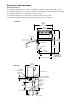
Installing dispenser in counter
Note: All dispensers must be supported from below with supplied 6" – 9" (153 – 229 mm) adjustable leg accessory,
or equivalent. Do not hang dispenser on ange.
All dispensers must be installed level in both directions to ensure proper operation.
1. Check that dispenser location meets all requirements in this manual and cut counter as shown.
2. Place support blocks in cabinet to raise dispenser to a height of 12" (305 mm).
3. Place dispenser in counter onto support blocks.
4. Attach adjustable legs to dispenser.
5. Remove support blocks and lower dispenser feet to oor.
6. Adjust legs for 1/8" (4 mm) clearance between dispenser lip and countertop to verify there is no load on ange.
7. Apply a bead approximately 1/4" (6 mm) in diameter of NSF-listed silicone sealant (Dow Corning RTV-732 or
equivalent) around perimeter of dispenser where it meets counter. Smooth sealant to a 1/8" (4 mm) radius.
8. Install a PVC drain line with at least a 1/4" per foot (20 mm per 1 m) slope. Insulate drain line to prevent
condensation.
Note: Do not apply excessive heat if any sweating of ttings is necessary. Heat conduction through metal
may melt threads in plastic drain.
Do not reduce drain line size or tie drains together.
9. Make electrical connections in accordance with applicable wiring diagrams provided. Provide disconnects within
10 ft (3 m) of dispenser and ice machine for servicing.
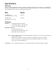
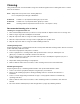
front of counter
+.125"
- .125"
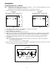
30.375"
(772mm)
+3 mm
- 3 mm
26.25"
+.125"
- .125"
(667mm)
+3 mm
- 3 mm
26.25"
front of counter
+.125"
- .125"
+.125"
- .125"
36.375"
(924mm)
+3 mm
- 3 mm
(667mm)
+3 mm
- 3 mm
Plan View
units with up to 8 valves counter cut-out
Plan View
units with 10 valves counter cut-out
6
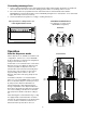
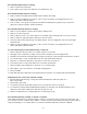
Bin thermostat capillary tube mounting
tabs in ice tube
retainer bracket
engage holes in ice
tube and hold tube
in place
ice tube
ice tube
retaining
bracket
thermostatthermostat
ice tube
retaining
bracket
thermostat
Front View, VU300
Front View, VU155
ice tube