
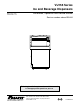
Owners Manual

carbonated
non-carbonated
Operation
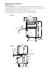
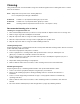
How the dispenser works
Follett’s dispensers are available in automatic load
congurations, fed from one or two Follett RIDE
model ice machines or manual load congurations
(using ice from another source).
In all models, ice is stored below the counter in the
dispenser storage area. When the dispense lever
or button is pushed, the dispense motors are
activated. This causes the wheel assembly in the
storage area to turn, moving ice to the vertical
auger assembly, which carries ice up to the
dispense chute where it drops by gravity into the
container.
In automatic load units, ice is manufactured in
either one or two Follett RIDE model ice machines.
These ice machines may be located up to 20 ft (6
m) away from the dispenser. Extruded ice is
transported through a tube and pushed to the
storage compartment of the dispenser. When the
bin is lled, a bin thermostat shuts the ice machine
off to avoid overlling of the bin. The ice machine
will restart after 20 minutes if the bin is calling for
ice.
Units with integral ice water bath beverage cooling
are equipped with a water bath timer circuit that
activates the water bath pump for 35 minutes when
ice lever or button is activated, or when the ice
water bath warms up and calls for more ice.
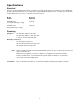
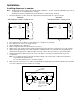
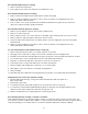
Connecting beverage lines
1. Connect syrup and water lines. Non-carbonated water line will be labeled “water”. Syrup lines are numbered
and correspond to the valves as shown in drawing(s) below. Valve one is always next to ice tower.
2. The center 4 valves are pre-plumbed to both carbonated and non-carbonated water lines with the
QuickCARB
™
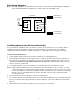
beverage manifold. Valves can be individually changed from a carbonated to a non-carbonated
avor with the ip of a lever (see below).
3. Clean and sanitize beverage lines according to cleaning instructions.
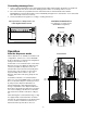
Ice movement
1
2
34
56
7
8910
Valve position #1 is always next to ice
tower. Right-hand unit shown.
VU155B QuickCARB manifold
(see dispenser for model specic
QuickCARB conguration)
Rear View
8