
Owners Manual

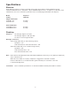
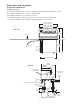
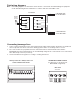

Field wiring diagrams
Note: Field wiring diagrams are intended to aid electricians or technicians in understanding how equipment
works. All eld wiring must be installed in accordance with all local and NEC codes.
DISPENSER
LEFT JUNCTION BOX
RIGHT JUNCTION BOX
BL
Y
RD
CONVERTER BOX
TO ICE MACHINE 2
CONVERTER BOX
TO ICE MACHINE 1
Electric
Power
Source
GND
GRN
B
W
10
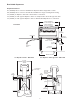
Connecting beverage lines
1. Connect syrup and water lines. Non-carbonated water line will be labeled “water”. Syrup lines are numbered
and correspond to the valves as shown in drawing(s) below. Valve one is always next to ice tower.
2. The center 4 valves are pre-plumbed to both carbonated and non-carbonated water lines with the
QuickCARB
™
beverage manifold. Valves can be individually changed from a carbonated to a non-carbonated
avor with the ip of a lever (see below).
3. Clean and sanitize beverage lines according to cleaning instructions.
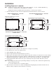
Valve position #1 is always next to ice
tower. Left-hand unit shown.
10987654321
carbonated
non-carbonated
VU300B QuickCARB manifold
(see dispenser for model specic
QuickCARB conguration)
Rear view