FoMaKo -Upgrade Your Meeting Experience - www.fomako.net Conference PTZ Camera Control Keyboard --- KC-601 User Manual (V1.
Content 1.Product Overview................................................................................................................................................... 1 1.1 Product Features....................................................................................................................................... 1 1.2 Technical Parameters............................................................................................................................... 1 1.3 Precautions.........
1 Statement: The descriptions in this manual may differ from the version you are using. If you are having trouble during using this manual, please contact our technical support for assistance. The contents of this manual will be updated, and our company reserves the right to leave it without notice. Precautions The controller is an indispensable device in the integrated video conferencing system, providing full control of all front-end cameras, pan/tilt and motorized lenses.
2 Interfaces 5PIN Crimping terminal,RS232 Port Joystick Rocker 3D Control:Up,Down,Left,Right,Rotate) Display Blue screen LCD Input voltage DC12V±10% Power Consumption 6W MAX Temperature -10℃~50℃ Humidity ≦90%RH(No frosting) Dimension 320mm(L)X179.3mm(W)X106.4mm(H) 1.3 Precautions LCD Screen is fragile, do not squeeze or leave under harsh light for too long. The joystick rocker is fragile. Do use the original package or properly packaged before shipment back.
3 【ESC】Exit and back to former menu. 【SETUP】Parameter setting button:Long press 3S to enter the KBD parameter setting status 【CAM ON/OFF】Camera power on/off button 【AF/MF】Auto focus / manual focus: Manual focus need to work together with [FOCUS]+ or [FOCUS-] button. 【SET PRESET】Presets setting button, working together with number keys and the [ENTER] button. 【CALL PRESET】Call presets button, working with the number keys and the [ENTER] button.
4 2.4 Back Panel Interfaces Back Panel Details: 1x 5PIN crimping terminal interface,1 x RS232 interface,1xDC-12V power socket,3 x indicator lights as picture below: 2.5 Functional number description Number Label Physical interface Description 1. (Ta)to connect RS485+,(Tb)to connect RS485- ① RS-422 ② Ground ③ PW ④ TXD ⑤ RXD ⑥ DC-12V 2.
5 3. Parameter Setting and Query 3.1 PTZ Setup E.g. With address code 28, steps to change to Pelco-P protocol and baud rate to 9600 are as follows: Press【SETUP】button for 3 seconds under normal working mode, it displays as follows: Press【Enter】 Enter password(default is 8888) Press【2】 【8】 Move joystick downward Press【Enter】 Move joystick rightward to choose to the right baudrate choose the right protocol Then press 【ENTER】,there will be a 1sec beep sound when setting done.
6 done. Press【ESC】twice to back to normal working mode. 3.2.2 Restore Factory Setting Press【SETUP】button for 3 seconds under working mode, it displays as follows : Enter password Move joystick downward press 【Enter】 Move joystick downward press 【Enter】 Press 【ENTER】,there will be a 1sec beep sound when setting done. Press 【ESC】 twice to back to normal working mode. 3.
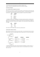
7 Device number:XX 2 digits keyboard ID number Keyboard lock(ON/OFF) Display the current setting of the keyboard lock Sound(ON/OFF) Display the setting of the current button sound prompts 4.Typical wiring diagram 4.
8 1.control output:connect camera RS485+ with keyboard Ta, RS485- with Tb. 2.Deputy control device:either RS485 output from DVR or keyboard is available. 4.2 Connection Analysis 4.2.
9 5. Appendix 5.1 RS485 bus introduction: RS485 bus, RS is the abbreviation of English "recommended standard", 485 is the identification number. The RS485 serial bus is widely used in applications where the communication distance ranges between dozens of meters to 1km more. RS485 uses balanced transmitting and split receiving, so it has the ability to reject common mode interference.
10 5.4 Problems in Actual Application The star link mode will always be used in actual constructions, requiring the terminating resistor to be linked with the two devices in the farthest distance. But it does not meet the requirements of the RS485 industry standards. When the distance between each device are too long, signal reflection and anti-interference ability reducing would frequently happen,which will decrease the reliability of the control signal.
11 indicator light flickering when flickers when control, then there control. is no problem with KBD. Step 2: If the PTZ indicator light does not flash when control, there is some problem with the RS485 output of the keyboard. Please return to factory for repairing. 1.check the control cable Video conference camera can not be controlled by KBD Make sure a right connection of the control cable. Check whether the current 2.
12 Copyright Statement All the contents in this manual and its copyright are owned by the company. No one is allowed to imitate, copy, or translate this manual without the company’s permission. This manual contains no guarantee, standpoint expression or other implies in any form. Product specification and information in this manual is for reference only and subject to change without notice. All rights reserved. No reproducing is allowed without acknowledgement.