
User Manual


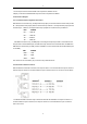
Table Of Contents

8
8
1.control output:connect camera RS485+ with keyboard Ta, RS485- with Tb.
2.Deputy control device:either RS485 output from DVR or keyboard is available.
4.2 Connection Analysis
4.2.1 connection between keyboard and camera
With RS422 bus connection way, the keyboard third pin (Ra) is connected with the camera third pin TXD
IN- , the keyboard fourth pin (Rb) with the camera fourth pin TXD IN+ , the keyboard first pin(Ta ) with the
camera first pin RXD IN-, the keyboard second pin (Tb)with the camera second pin RXD IN +.
KBD CAMERA
Ra<········>TXD IN-
Rb<········>TXD IN+
Ta<········>RXD IN-
Tb<········>RXD IN+
With RS232 connection way, the KBD(10pin connecting terminal) first pin RXD is connected with the
third pin TXD of camera RS232 port, the KBD second pin TXD with the camera fifth RXD, the KBD third
GND with the camera forth pin GND.(It is also available to connect camera with the standard RS232 port
on the KBD.)
KBD CAMERA
RXD<········>TXD
TXD<········>RXD
GND<········>RXD
The camera can be controlled by any connection way mentioned above.
4.2.2 Connection between cameras
With the RS422 bus cascade connection, the output of camera 1 is connected with the input of camera 2,
and the output of camera 2 is connected with the input of camera 3,and so on so forth. As shown below:
The RS232 cascade connection way is almost the same as that of RS422. The output of camera 1 is
connected with the input of camera 2, the output of camera 2 is connected with the input of camera 3,
and so on so forth.