
User Manual


10
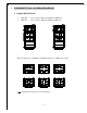
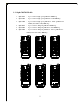
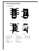
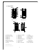
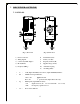
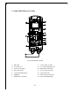
5.2 Alpha 500/520 Internal Assembly
(Fig. 11) Internal Parts Assembly
1) RX module 8) Contact output seat (CN3)
2) Power fuse (AC) 9) Low voltage warning fuse (LV)
3) Spare fuses & jumpers 10) Pushbutton #3 and #4 fuse
4) ID code dip-switch 11) AC power input seat (CN2)
5) Contact relay LED displays 12) Output cable mouth
6) MAIN fuse 13) Reserved output cable mouth
7) Pushbutton #1 and #2 fuse 14) System status LED display
FUSE
FUSE
FUSE
FUSE
FUSE