
User Manual


7
4.
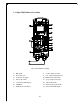
TRANSMITTER OUTLINE
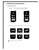
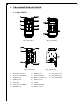
4.1 Alpha 500/520
(Fig. 1) Front View (Fig. 2) Back View
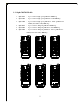
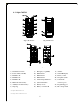
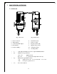
(Fig. 3) Front View (Fig. 4) Back view
1) Transmitter enclosure 8) Pushbutton # 3 15) TX quartz crystal
2) Power switch (ON/OFF) 9) System information 16) Programming port
3) Pushbutton #2 10) Battery cover/FCC ID 17) ID code dip-switch
4) Pushbutton #4 11) Battery screws
5) Strap ring 12) Antenna
6) Emergency stop (EMS) 13) Status LED display
7) Pushbutton #1 14) Battery contact
1
2
3
4
5
6
7
8
9
10
11
O N O FF STO P
12
13
14
15
16
17