
User Manual


8
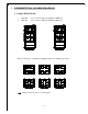
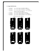
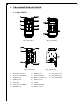
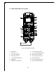
4.2 Alpha 540/560
(Fig. 5) Front View (Fig. 6) Back View
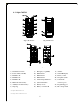
(Fig. 7) Front View (Fig. 8) Back View
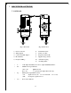
1) Transmitter enclosure 9) Emergency stop (EMS) 17) Antenna
2) Power switch (ON/OFF) 10) Pushbutton #1 18) Status LED display
3) Pushbutton #2 11) Pushbutton #3 19) Battery contact
4) Pushbutton #4 12) Pushbutton #5 20) TX quartz crystals
5) Pushbutton #6 13) Select/AUX pushbutton** 21) Select/AUX
6) Main hoist and/or trolley* 14) System information connector port**
7) Auxiliary hoist and/or trolley* 15) Battery screws 22) Programming port
8) Strap ring 16) Battery cover/FCC ID 23) ID code dip-switch
* For Alpha 540T/560T models only.
** For Alpha 540/560 A and T models only.
On
1
2
3
4
7
5
6
8