
User's Manual
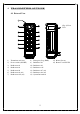


7
18
19
17
16
15
14
12
5
9
7
8
6
1
3
4
2
10
11
13
5.
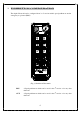
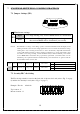
RECEIVER OUTLINE
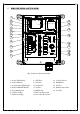
(Fig. 6) Receiver Internal Assembly
1) Power LED Display 8) E/W Fuse 15) Voltage Selector
2) SQ Led Display 9) N/S Fuse 16) MAIN Fuse
3) System Status LED Display 10) A1/A2 Fuse 17) A4 Fuse
4) Relay COM LED Display 11) A3 Fuse 18) Primary Power Fuse
5) Programming Port 12) RX Module 19) L/V Fuse
6) Jumper Settings 13) ID Code Dip-Switch
7) Function Settings 14) Secondary Power Fuse