
User Manual

7
4
4
.
.
T
T
R
R
A
A
N
N
S
S
M
M
I
I
T
T
T
T
E
E
R
R
O
O
U
U
T
T
L
L
I
I
N
N
E
E
4
4
.
.
1
1
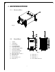
T
T
r
r
a
a
n
n
s
s
m
m
i
i
t
t
t
t
e
e
r
r
B
B
o
o
x
x
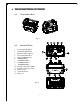
(Fig. 1)
4
4
.
.
2
2
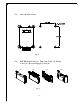
D
D
e
e
t
t
a
a
i
i
l
l
e
e
d
d
P
P
a
a
r
r
t
t
s
s
1. Power Status LED Display
2. Signal Status LED Display
3. Information Plate (engraved)
4. Left Joystick Rubber Boot
5. Right Joystick Rubber Boot
6. START Pushbutton
7. AUX/RES Pushbutton
8. AUX/RES Pushbutton
9. AUX/RES Pushbutton
10. Emergency Stop Button (EMS)
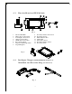
11. Power Key Switch (removable)
12. Battery Contact
13. System Information
14. Battery slot
(Fig. 2)
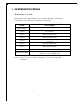
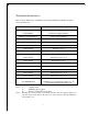
MODEL
VOLTAGE
BAND
POWER
S/NO.
0
1
2
3
4
5
6
7
8
9
A
CHANNEL A B C
B C
:
:
:
:
:
:
V
m
MHz
RXWTX W