
User Manual

8
4
4
.
.
3
3
E
E
n
n
c
c
o
o
d
d
e
e
r
r
B
B
o
o
a
a
r
r
d
d
a
a
n
n
d
d
P
P
L
L
L
L
M
M
o
o
d
d
u
u
l
l
e
e
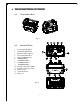
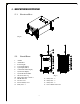
(Fig. 3)
1. Encoder Shield Plate 9. Power Key Switch Connector Port
2. Ribbon Type Connector Port 10. Power Fuse (0.25A)
3. Power Input Connector Port 11. Infrared Interface Port
4. Charger Connector Port 12. Antenna Port
5. TX Module Connector Port 13. TX module Connector
6. ID Code Dip-Switch 14. Power Key Switch Connector
7. Frequency Channel Dip-Switch 15. Power Key Switch
8. Programming Port
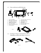
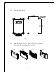
(Fig. 4)
4
4
.
.
4
4
I
I
n
n
t
t
e
e
l
l
l
l
i
i
g
g
e
e
n
n
t
t
C
C
h
h
a
a
r
r
g
g
e
e
r
r
,
,
6
6
0
0
0
0
m
m
A
A
B
B
a
a
t
t
t
t
e
e
r
r
y
y
P
P
a
a
c
c
k
k
x
x
2
2
,
,
W
W
a
a
i
i
s
s
t
t
B
B
e
e
l
l
t
t
,
,
a
a
n
n
d
d
S
S
h
h
o
o
u
u
l
l
d
d
e
e
r
r
S
S
t
t
r
r
a
a
p
p
(Not Pictured)
(Fig. 5)