
User Manual


10
EN
NORTHWOOD
™
1/10 4WD SCALER
Transmitter
Frequency 2.4GHz
Channels 2
Power supply 4 AA cells
2 in 1 Electronic Speed Control (ESC)/Receiver
Input Voltage 6.0–8.4 V DC
Electric Capacity (FET) Forward 20A/320A
Electric Capacity (FET) Reverse 20A/320A
PWM Frequency 1kHz
BEC Voltage 6V/2A
Weight 50 g
Size 63.7 × 36.1 × 23.5mm
Servo
Voltage 4.8V~6V
Output Torque 161 oz/in @ 6.0V
Operating Speed .24 sec/60 degrees @ 6.0V
Size 40.2 × 20.1 × 38.1mm
Battery
Type Ni-MH
Capacity 2000 mAh
Motor
Type 540 Brushed
Turns 20 turn
COMPONENT SPECIFICATIONS
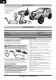
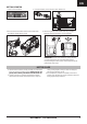
BINDING
Binding is the process of programming the receiver to recognize
the GUID (Globally Unique Identifi er) code of a single specifi c
transmitter. The FCES1308 transmitter and FCES13002 2-in-1
receiver/ESC are bound at the factory. If you need to rebind,
follow the instructions below.
1. Connect power to the ESC/receiver unit.
2. Turn power on. The red LED will begin to blink slowly.
3. Insert the bind plug into the 2 pin bind port on the ESC/
receiver unit. The red LED will begin to flash quickly.
4. Power up the transmitter. Once the red LED turns solid,
binding is complete, Remove the bind plug from the ESC/
receiver unit.
FAILSAFE
In the unlikely event that the radio link is lost during use, the
receiver will set the throttle to its pre-programmed failsafe
position. If the receiver is turned on prior to turning on the
transmitter, the receiver will enter failsafe mode. When the
transmitter is turned on, normal throttle control is resumed.
To set failsafe, begin with the throttle at neutral, then press and hold
the button on the receiver until the
LED begins to flash quickly. When
the LED changes to be steadily lit,
the failsafe position is set.
Failsafe must be set every time
the system is bound. Binding will
reset the failsafe setting.
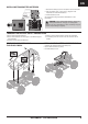
SHOCK CLEANING
Oil-fi lled shocks will require regular maintenance due to the oil breaking down or getting dirty. This
maintenance should be performed after about every 3 to 5 hours of use, depending on the conditions
that the vehicle is used in.
• Remove the shock from the vehicle.
• Remove the cap from the shock body and dispose of fluid.
• Disassemble the shock. Clean thoroughly with DYN5505. Dry parts before assembly.
• Re-assemble the shock and refill the shock body with silicone fluid (30 weight recommended).
• Slowly move the shaft and piston up and down to remove air bubbles.
• Move the piston to the midway point of the body and install the cap.
• Wipe off any overflowing fluid.
• When properly filled, the piston should rebound about 3/8 in (9.5mm) after being pushed in fully.
• Re-install the shock on the vehicle.
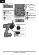
SHOCK PARTS
DIAGRAM
Item # Part # Description
23 FCES234007 Linkage Ball Cup and Shock Plastics Set, Hammerjaw, Northwood
27 FCES233005 Shock absorber set, Hammerjaw, Northwood
28 FCES233006 Shock spring set, Hammerjaw, Northwood
23
23
23
28
27
23