® ® F-18 Blue Angel Instruction Manual Manuel d’utilisation
EN NOTICE All instructions, warranties and other collateral documents are subject to change at the sole discretion of Horizon Hobby, LLC. For up-to-date product literature, visit www.forcerc.com and click on the support tab for this product.
EN Box Contents Quick Start Information Transmitter Setup Dual Rates 1. Blank (Acro) Model 2. Servo Reversing: Normal 3. Travel Adjust (All Surfaces): 100% Extreme Flying Normal Flying =14mm =14mm =12mm =12mm =10mm =10mm =8mm =8mm High 15% 20% Low 5% 5% Ail Ele EXPO Ail (Soft center) Ele Center of Gravity (CG) 80–85mm back from leading edge at the root.
EN Preflight 1 Remove and inspect contents. 8 Make sure linkages move freely. 2 Read this instruction manual thoroughly. 9 Perform the Control Direction Test with the transmitter. 3 Charge flight battery. 10 Perform the AS3X Control Direction Test with the aircraft. 4 Fully assemble airplane. 11 Adjust flight controls and transmitter. 5 Install the flight battery in the aircraft (once it has been fully charged). 12 Perform a radio system Range Test. 6 Check the Center of Gravity (CG).
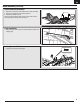
EN Model Assembly (Continued) Vertical Stabilizer Installation 1. Apply CA to the base of the vertical stabilizer where it meets the fuselage. 2. Apply CA to the fuselage where the vertical stabilier fits. 3. Fit the vertical stabilizer in the slot. Make sure the vertical stabilizer angles outward as shown. Also make sure both vertical stabilizers are angled the same amount. Clevis Installation 1. Attach the clevises to the control horns. Additional details are located on the following pages.
EN Model Assembly (Continued) Missile Installation 1. Use CA to attach the missiles to the aircraft. Refer to the illustration for the correct location for each item. Nose Cone Installation 1. Apply CA to the fuselage where the nose cone fits. Ensure the nose cone is oriented correctly. PNP Receiver Selection and Installation The Spektrum AR636A receiver is recommended for ths airplane. If you choose to install another receiver, ensure that it is at least a 4-channel full range (sport) receiver.
EN Battery Installation and ESC Arming Battery Selection A We recommend the Kinexsis® 14.8V 2400mAh 30C 4S LiPo Battery, 12AWG: EC3™ (KXSB0016) for standard operation. If using a different battery, the battery should be of similar capacity, dimensions and weight of the Kinexsis Li-Po battery pack to fit in the fuselage. Always be sure the model balances at the recommended CG with the battery chosen. 1. Lower the throttle and throttle trim to the lowest settings.
EN Clevis Installation and Control Centering Clevis Installation • Pull the tube from the clevis to the linkage. • Carefully spread the clevis, then insert the clevis pin into the desired hole in the control horn. • Move the tube to hold the clevis on the control horn. 1 4 2 5 3 6 Control Surface Centering After assembly and transmitter setup, confirm that the control surfaces are centered. If the control surfaces are not centered, mechanically center the control surfaces by adjusting the linkages.
EN Power Components Service CAUTION: Always disconnect the flight battery before performing motor service. A Disassembly 1. 2. 3. 4. 5. 6. Remove the wing, disconnecting servos as needed. Disconnect the motor connectors from the ESC connectors. Remove the 2 screws (A) to remove the fan cover. Remove the 2 screws (B) and fan unit (C) from the fuselage. Remove the screw (D) and spinner (E) from the collet (F). Remove the nut (G) rotor (H), washer (I) backplate (J) and collet from the motor.
EN Control Surface Direction Ailerons Switch on the transmitter and connect the battery. Use the transmitter to operate the ailerons. View the aircraft from the rear when checking the control directions. 1. Move the stick to the left. The right aileron will move down and the left aileron move up, causing the aircrat to bank left. 2. Move the stick to the right. The right aileron will move up and the left aileron move down, causing the aircraft to bank right. Elevators 3.
EN Flying Tips and Repairs (Continued) Landing Low Voltage Cutoff (LVC) For your first flights with the recommended battery pack (KXSB0016), set your transmitter timer or a stopwatch to 3 minutes. After three minutes, land the aircraft. Adjust your timer for longer or shorter flights once you have flown the model. If at any time the motor pulses, land the aircraft immediately to recharge the flight battery. See the Low Voltage Cutoff (LVC) section for more details on maximizing battery health and run time.
EN Troubleshooting Guide Problem Aircraft will not respond to throttle but responds to other controls Extra noise or extra vibration during throttle operation Reduced flight time or aircraft underpowered Aircraft will not connect (during binding) to transmitter Aircraft will not connect (after binding) to transmitter Control surface does not move Controls reversed Motor power pulses then motor loses power 12 Possible Cause Solution Throttle not at idle and/or throttle trim too high Reset control
EN AMA National Model Aircraft Safety Code Effective January 1, 2014 A. GENERAL A model aircraft is a non-human-carrying aircraft capable of sustained flight in the atmosphere. It may not exceed limitations of this code and is intended exclusively for sport, recreation, education and/or competition. All model flights must be conducted in accordance with this safety code and any additional rules specific to the flying site. 1. Model aircraft will not be flown: (a) In a careless or reckless manner.
EN Limited Warranty What this Warranty Covers Horizon Hobby, LLC, (Horizon) warrants to the original purchaser that the product purchased (the “Product”) will be free from defects in materials and workmanship at the date of purchase.
FR REMARQUE Toutes les instructions, garanties et autres documents de garantie sont sujets à la seule discrétion de Horizon Hobby, LLC. Veuillez, pour une littérature produits bien à jour, visiter www.forcerc.com et cliquer sur l’onglet de support de ce produit.
FR Contenu de la boîte Guide de démarrage rapide Paramètres émetteur Doubledébattements 1. Programme avion vierge 2. Direction des servos : Normal 3.
FR Liste des opérations à effectuer avant le vol 1 Retirez les éléments de la boîte et inspectez-les. 8 Contrôlez le mouvement des tringleries de commande. 2 3 Lisez attentivement le présent manuel d’utilisation. 9 Vérifiez que les tringleries bougent librement. Chargez la batterie de vol. 10 Effectuez un essai de la réponse de l’AS3X. 4 Assemblez le modèle complètement. 11 Réglez les tringleries et l’émetteur. 5 Installez la batterie dans le modèle (Une fois la charge terminée).
FR Assemblage du modèle (Suite) Installation du stabilisateur horizontal 1. Appliquez de la colle cyanoacrylate sur la base du stabilisateur horizontal qui s’insérera dans le fuselage. 2. Appliquez de la colle cyanoacrylate dans le fuselage au niveau de la fente du stabilisateur horizontal. 3. Insérez le stabilisateur horizontal dans la fente. Assurez-vous que le guignol de contrôle est orienté vers le bas du fuselage. Assurez-vous que le stabilisateur horizontal est aligné avec l’aile.
FR Assemblage du modèle (Suite) Installation du train d’atterrissage 1. Installez (4) vis pour fixer le train d’atterrissage. 2mm X 8mm Installation des missiles 1. Utilisez de la colle cyanoacrylate pour fixer les missiles à l’appareil. Consultez l’illustration pour l’emplacement correct de chaque objet. Installation du cône de nez 1. Appliquez de la colle cyanoacrylate dans le fuselage au niveau du logement du cône de nez. Assurez-vous que le cône de nez est orienté correctement.
FR Version PNP Choix et installation du récepteur Le récepteur Spektrum AR636A est recommandé pour cet avion. Si vous désirez utiliser un autre récepteur, il devra avoir 4 voies au minimum et avoir une longue portée. Référez-vous au manuel de votre récepteur pour consulter les instructions relatives à son installation et son utilisation. Installation (AR636 représenté) 1. Retirez la trappe du fuselage. 2. Installez le récepteur à la parallèle à la longueur du fuselage comme sur l’illustration.
FR Installation des manilles et centrage des commandes Connexion des tringleries • Glissez le morceau de durite vers la tringlerie. • Ecartez délicatement la chape et glissez l’axe de la chape dans le trou approprié du guignol. • Glissez l’anneau vers le milieu des fo approprié du urches de la chape. 1 4 2 5 3 6 Réglage du neutre des gouvernes Contrôlez le neutre des gouvernes après avoir effectué l’assemblage du modèle et la programmation de l’émetteur.
FR Réparation des pièces électriques A ATTENTION: Toujours déconnecter la batterie avant d’effectuer la maintenance de la motorisation. Démontage B 1. 2. 3. 4. 5. 6. Démontez l’aile, en débranchant les servos au besoin. Débranchez les connecteurs du moteur des connecteurs du variateur ESC. Retirez les 2 vis (A) pour retirer le capot de la soufflante. Retirez les 2 vis (B) et la soufflante (C) du fuselage. Retirez la vis (D) et le cône (E) de la bague de serrage (F).
FR Direction des gouvernes Ailerons Allumez l’émetteur et raccordez la batterie. Utilisez l’émetteur pour commander les ailerons. Mettez-vous derrière l’appareil pour vérifier les gouvernes. 1. Déplacez le manche vers la gauche. L’aileron droit s’abaissera et l’aileron gauche s’élèvera, pour faire pencher l’appareil vers la gauche. 2. Déplacez le manche vers la droite. L’aileron droit s’élèvera et l’aileron gauche s’abaissera, pour faire pencher l’appareil vers la droite. Gouvernes de profondeur 3.
FR Conseils de vol et réparations (Suite) Atterrissage Coupure par tension faible (LVC) Pour les premiers vols avec la batterie recommandée (KXSB0016), réglez la minuterie de l’émetteur ou de votre montre sur une durée de 3 minutes. Une fois les 3 minutes écoulées, posez l’appareil. Posez immédiatement l’avion quand le moteur émet des pulsations et rechargez la batterie. Consultez la section relative au LVC pour des informations complémentaires relatives à l’entretien de la batterie et l’autonomie.
FR Guide de dépannage Problème L’aéronef ne répond pas aux gaz mais bien aux autres commandes L’hélice fait trop de bruit ou vibre trop Cause possible Solution La manette des gaz n’est pas au ralenti (idle) et/ou le trim des gaz est régléà une valeur trop élevée Réinitialiser les commandes avec la manette des gaz et mettre le trim des gaz à sa valeur la plus faible possible La course du servo des gaz est inférieure à 100% S’assurer que la course du servo des gaz est de 100% La voie des gaz est inv
FR Garantie Limitée Ce que couvre cette garantie Horizon Hobby, LLC, (Horizon) garantit à l’acheteur original que le produit acheté (le « Produit ») est exempt de tout défaut matériel et de fabrication à la date d’achat.
Replacement Parts • Pièces de rechange Part # | Numéro Description Description FCEF260001 Fuselage: F18 Blue Angel V2 Fuselage : F18 Blue Angel V2 FCEF260002 Main Wing Set: F18 Blue Angel V2 Ensemble d’ailes principales : F18 Blue Angel V2 FCEF260003 Rudder: F18 Blue Angel V2 Gouverne de direction : F18 Blue Angel V2 FCEF260004 Elevator: F18 Blue Angel V2 Gouverne de profondeur : F18 Blue Angel V2 FCEF260005 Missle-1 (2): F18 Blue Angel V2 Missile-1 (2) : F18 Blue Angel V2 FCEF260006 Miss
® F-18 Blue Angel ® ©2017 Horizon Hobby, LLC. Force RC, the Force RC logo, E-Flite, Plug-N-Play, DSM2, DSMX, Kinexsis, EC3, Celectra, Prophet and the Horizon Hobby logo are trademarks or registered trademarks of Horizon Hobby, LLC. The Spektrum trademark is used with permission of Bachmann Industries, Inc. Blue Angel and associated logos and body designs are trademarks or registered trademarks of the Office of Naval Research and are used with permission.