Dell Force10 MXL 10/40GbE Switch IO Module Getting Started Guide June 2012 Regulatory Model: DF10MXL
Notes, Cautions, and Warnings NOTE: A NOTE indicates important information that helps you make better use of your device. CAUTION: A CAUTION indicates potential damage to hardware or loss of data if instructions are not followed. WARNING: A WARNING indicates a potential for property damage, personal injury, or death. ____________________ Information in this publication is subject to change without notice. © 2012 Dell Inc. All rights reserved.
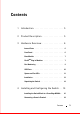
Contents 1 Introduction . 2 Product Description . . . . . . . . . . . . . . . . . 5 3 Hardware Overview . . . . . . . . . . . . . . . . . . 6 . . . . . . . . . . . . . . . . . . . . . . . 6 . . . . . . . . . . . . . . . . . . . . . . . . 6 Internal Ports. Front Panel . Base Module . . . . . . . . . . . . . . . . . . . . . . . . . . . . . . . . . . . . . . . . . . . . . . . FlexIOTM Plug-in Modules . Port Numbering USB Ports 7 . . . . . . . . . . . . . . . . . . . . . . 9 10 . . . . . .
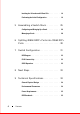
Invoking the X-Loader and U-Boot CLIs . Performing the Initial Configuration . 5 Assembling a Switch Stack . Configuring and Bringing Up a Stack Managing a Stack 19 . . . . . . . . . . 19 . . . . . . . . . 25 . . . . . . . . . . 26 . . . . . . . . . . . . . . . . . . . . 28 6 Splitting 40GbE QSFP+ Ports into 10GbE SFP+ Ports . . . . . . . . . . . . . . . . . . . . . . . . . . . . 30 7 Switch Configuration . DCB Support . . . . . . . . . . . . . . . . . . . . . . . . . . . . . . . . . . . .
Introduction This document provides basic information about the Dell Force10 MXL 10/40GbE Switch IO Module, including how to install the switch in the Dell PowerEdge M1000e Enclosure and perform the initial configuration. For more detailed information about any of the basic installation steps, refer to the Dell PowerEdge M1000e Enclosure Owner's Manual on the Dell Support website at http://support.dell.com/manuals.
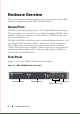
Hardware Overview This section contains information about device characteristics and modular hardware configurations for the MXL 10/40GbE Switch. Internal Ports The MXL 10/40GbE Switch provides 32 1/10-Gigabit Ethernet internal ports. The internal ports are connected to server blades through the M1000e chassis midplane. Each port can operate in either 1GbE or 10GbE mode. Internal ports are numbered 1 to 32.
Base Module The MXL 10/40GbE Switch provides two native 40-Gigabit Ethernet fixed ports on the base module for uplink connections. You can use these ports with 4x10G breakout cables to operate as 10GbE uplink ports. In addition, you can configure the native 40GbE ports as stacking ports. You can connect up to six MXL 10/40GbE Switches (in the same or different chassis) in a single stack. For more information, refer to "Assembling a Switch Stack" on page 25.
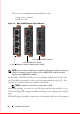
Then save the configuration and reload the switch. FTOS# write memory FTOS# reload Figure 1-2. MXL 10/40GbE Switch: Plug-in Modules 2-Port 40GbE QSFP+ Module 4-Port 10GbE SFP+ Module 4-Port 10GBASE-T Module (100Mb/1GbE/10GbE) NOTE: You can only hot-swap plug-in modules of the same type without requiring a reboot. For example, you can replace a 2-Port 40GbE QSFP+ module only with another 2-Port 40GbE QSFP+ module.
Port Numbering When installed in a PowerEdge M1000e Enclosure, the MXL 10/40GbE Switch ports are numbered 33 to 56 from the bottom to the top of the switch: • 40GbE base-module ports: • In 40GbE mode of operation, the ports are numbered 33 and 37. • In 4x10GbE mode of operation, the ports are numbered 33 to 36 and 37 to 40. For information about how to change a 40GbE port to 4x10GbE mode, refer to "Splitting 40GbE QSFP+ Ports into 10GbE SFP+ Ports" on page 30.
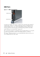
USB Ports Figure 1-3. USB Ports on Front Panel USB Storage Port USB Console Port Use the lower USB console port to configure the switch through an RS-232 serial interface (Figure 1-3). This port provides a direct connection to the switch and allows you to access the command line interface (CLI) from a console terminal connected to the port through the provided serial cable (with USB type-A to female DB-9 connectors).
System and Port LEDs The front panel of the MXL 10/40GbE Switch contains light emitting diodes (LEDs) that provide information about the status of the switch (Figure 1-4). Figure 1-4. System LEDs on Front Panel 40GbE Ports System Status LED System Power LED Table 1-1 describes system LED conditions. Ta b l e 1 - 1 . System LEDs System LED Color Meaning Green Power is being supplied to the switch. Off The switch does not have power.
Each plug-in module also contains LEDs that provide information about the link status and traffic activity on a port (Figure 1-5). Figure 1-5. Port LEDs on Modules Link Status Activity Link Status Activity Link Status Activity Table 1-2 describes the LED status of the 10GbE BASE-T, 10GbE SFP+, and 40GbE QSFP+ ports. Ta b l e 1 - 2 . Port LED Status Port LED Color Meaning Off The port is down. Green The port is up and can transmit traffic at maximum speed: A QSFP+ port can transmit at 40G.
Table 1-3 describes the LED status of a 40GbE QSFP+ port that is split into four 10GbE SFP+ ports using a 4x10G breakout cable. Ta b l e 1 - 3 . Cable LED Status of a 40GbE QSFP+ Port with Breakout Port LED Color Meaning Off All four 10GbE ports on a breakout cable are down. Yellow At least one of the four 10GbE ports on a breakout cable is up. Off No traffic is being transmitted on any 10GbE port on the breakout cable.
Unpacking the Switch Package Contents When unpacking each switch, make sure that the following items are included: • One Dell Force10 MXL 10/40GbE Switch IO Module • One USB type A-to-DB-9 female cable • Getting Started Guide • Safety and Regulatory Information • Warranty and Support Information • Software License Agreement Unpacking Steps NOTE: Before unpacking the switch, inspect the container and immediately report any evidence of damage.
Figure 1-6.
Installing the Switch Blade in a PowerEdge M1000e After you unpack the switch blade, slide it into one of the open I/O module slots in the back of a PowerEdge M1000e.
Figure 1-8. PowerEdge M1000e: Back View with Six MXL 10/40GbE Switch Blades After you slide the MXL 10/40GbE Switch in so that the connectors on the back of the blade touch the chassis midplane, the switch receives power from the chassis and automatically powers on. The chassis management controller (CMC) in the chassis validates that the switch blade is a supported I/O module before powering it on. When the switch powers on, the Boot loader loads the image from the local flash.
Connecting a Console Terminal After the MXL 10/40GbE Switch powers on, complete all external cabling connections and connect a terminal to the blade to configure the switch. NOTE: If you are installing a stack of MXL 10/40GbE Switches, connect the terminal to the console port on the Master Switch. If you connect the terminal to a member (non-Master) switch, you will not be able to use the CLI. For more information, refer to "Assembling a Switch Stack" on page 25.
Connect the USB connector on the cable directly to the switch console port. The console port on the MXL 10/40GbE Switch is located below the fixed 40GbE ports (Figure 1-3). Invoking the X-Loader and U-Boot CLIs During the boot process, you can perform various configuration tasks by accessing the X-Loader and U-Boot CLIs, such as running memory tests (X-Loader) and activating the backup image or recovering a password (U-Boot).
Before you start, to perform the initial switch configuration, you must obtain the following information from your network administrator: • The IP address to be assigned to the out-of-band (OOB) interface for device management. • The IP subnet mask for the OOB interface. • The IP address of the OOB interface default gateway. These settings are necessary to allow remote management of the switch through a Telnet (Telnet client) or HTTP (Web browser) connection.
Sample Setup Wizard Session This section describes an Easy Setup Wizard session. The following values are used in the example session: • SNMP is enabled. • The default user name "root" and password "calvin" are used. The Wizard does not display the password as it is entered. • The OOB management interface uses IP address 192.168.2.1. • The default gateway uses IP address 192.168.2.0. • The default VLAN management interface uses IP address 2.2.2.80.
. set up the initial SNMP version 2 account now. . return later and set up other SNMP accounts. (For more information on setting up an SNMP version 1 or 3 account, see the user documentation). Would you like to set up the SNMP management interface now? [Y/N] y To set up the SNMP management account you must specify the management system IP address and the "community string". The wizard automatically assigns read/write privilege to this account.
Next, IP addresses are set up on the OOB (Out-Of-Band) Interface and/or the VLAN1 routing interface. You can use these IP addresses to access the CLI, Web interface, or SNMP interface of the switch. To access the switch through any Management Interface you can . set up the IP address for the Management Interface. . set up the default gateway if IP address is manually configured on the OOB interface. Would you like to set up the Out-Of-Band interface now? [Y/N] y Please enter the IP address of the device (A.
This is the configuration information that has been collected: SNMP Interface = "mxl1"@1.1.1.1 User Account setup = root Password = ****** Out-of-band IP address = 192.168.2.1 255.255.255.0 VLAN1 Router Interface IP = 2.2.2.80 255.255.255.0 Default Gateway = 192.168.2.0 If the information is correct, please enter (Y) to save the configuration. If the information is incorrect, enter (N) to discard the configuration and restart the wizard: [Y/N] y Thank you for using the Dell Easy Setup Wizard.
Assembling a Switch Stack After you complete the initial switch configuration, the MXL 10/40GbE Switch is powered up and operational. Stacking is supported on the 40GbE ports on the base module or a 2-Port 40GbE QSFP+ module to connect up to six MXL 10/40GbE Switches in a single stack. Figure 1-9 shows an example using six MXL 10/40GbE Switches in a chassis. The MXL 10/40GbE Switches are connected to operate as a single stack in a ring topology using only the 40GbE ports on the base modules.
Use only QSFP transceivers and QSFP cables (separately purchased) to connect stacking ports as follows: 1 Insert a QSFP cable in the bottom stacking port on the rightmost switch. 2 Connect the upper stacking port on the next switch to the left. 3 Continue connecting each switch to the next in this way until you reach the leftmost switch in the stack. 4 On the leftmost switch, connect the bottom stacking port to the upper stacking port on the rightmost switch to create a loop.
lower 40GbE base-module port and stack-group 1 defines the stack group for the upper 40GbE base-module port. To display the ports in each stack group, enter the show system stack-unit unit-number stack-group command. 2 Save the stacking configuration on the 40GbE ports: FTOS# write memory 3 Repeat Steps 1 and 2 on each MXL 10/40GbE Switch in the stack by entering the stack-unit 0 stack-group 0 and stack-unit 0 stack-group 1 commands and saving the configuration.
management if the Master Switch fails. For example: FTOS> enable FTOS# configure FTOS(conf)# stack-unit 0 priority 14 The no form of the stack-unit unit-number priority number command reverts the management priority of a stack unit to the default value of 0. Managing a Stack Master and Member Switches You can manage a stack of MXL 10/40GbE Switches as a single entity when connected together.
Auto Stack Number Assignment During the stack formation process, a unique stack-unit number is assigned if the same number is assigned to more than one switch. After assignment is complete, each switch saves its stack-unit number. To view stack-unit numbers, enter the show system command. FTOS Version Checking Following the stack-unit number assignment, the Master Switch performs a consistency check to make sure that all switches in the stack are running the same FTOS version.
upgrading all switches in the stack, save the configuration (using the write memory command) and reload the stack to activate the new FTOS version (using the reload command). System Initialization The Master Switch initializes the stack using the last saved system configuration file. If you change the stack configuration, be sure to save the configuration file. The Master Switch automatically distributes the configuration file to the member switches.
stack-unit unit-number: Enter the number of the stack unit to be reset. Range: 0-5. To display the stack-unit number, enter the show system brief command. port port-number: Enter the port number of the 40GbE QSFP+ port to be split. Valid values on base module: 33 or 37; slot 0: 41 or 45; slot 1: 49 or 53. portmode quad: Identifies the uplink port as a split 10GbE SFP+ port. Then save the configuration and reload the switch.
DCB Support DCB enhancements for data center networks are supported to eliminate packet loss and provision links with required bandwidth. On the MXL 10/40GbE Switch, you must manually configure DCBX port roles to enable the switch to auto-configure its DCB settings to match the DCB configuration in the ToR switches to which it connects. FCoE Connectivity Many data centers use Fiber Channel (FC) in storage area networks (SANs).
Next Steps If you installed the MXL 10/40GbE Switch in a stack, you can configure additional settings for switch stacking. For information about how to create different stacking scenarios, refer to the Ethernet Stacking white paper on the Dell Support and Dell Networking White Papers websites at: http://support.dell.com/manuals http://en.community.dell.com/techcenter/networking/w/wiki/networkingwhitepapers.
Technical Specifications The MXL 10/40GbE Switch is an I/O module and installed with Server (model: PowerEdge M1000e) for communication. The product should be operated at an ambient temperature of 50°C. CAUTION: Lithium Battery Caution: There is a danger of explosion if the battery is incorrectly replaced. Replace only with same or equivalent type. Dispose batteries according to manufacturer's instructions. Chassis Physical Design Parameter Specifications Height 1.32 inches (33.45 mm) Width 10.
Power Requirements Parameter Specifications Power supply 100–240 VAC 50/60 Hz Maximum current draw per system 2 A @ 100/120 VAC 1 A @ 200/40 VAC Maximum power consumption 123 Watts Reliability MTBF 355,178 hours IEEE Standards The MXL 10/40GbE Switch complies with the following IEEE standards: • 802.1AB LLDP • 802.1ag Connectivity fault Management • 802.1D Bridging, STP • 802.1p L2 Prioritization • 802.1Q VLAN Tagging, Double VLAN Tagging, GVRP • 802.1s MSTP • 802.1w RSTP • 802.
Technical Specifications
Printed in the U.S.A. ww w.d el l .c o m | s up p or t . de l l.