Contents Before driving Introduction 2 Instrumentation 6 Controls and features 17 Seating and safety restraints 73 Starting and driving Starting 103 Driving 107 Roadside emergencies 128 Servicing Maintenance and care 148 Capacities and specifications 194 Customer assistance 202 Reporting safety defects 215 Index 216 All rights reserved.
Introduction The following warning may be required by California law: CALIFORNIA Proposition 65 Warning Engine exhaust, some if its constituents, and certain vehicle components contain or emit chemicals known to the State of California to cause cancer, or birth defects or other reproductive harm. ICONS Indicates a safety alert. Read the following section on Warnings. Indicates vehicle information related to recycling and other environmental concerns will follow.
Introduction BREAKING-IN YOUR VEHICLE There are no particular breaking-in rules for your vehicle. During the first 1 600 km (1 000 miles) of driving, vary speeds frequently. This is necessary to give the moving parts a chance to break in. INFORMATION ABOUT THIS GUIDE The information found in this guide was in effect at the time of printing. Ford may change the contents without notice and without incurring obligation. SPECIAL NOTICES Snowplowing Your vehicle is not recommended for snowplowing.
Introduction These are some of the symbols you may see on your vehicle.
Introduction Vehicle Symbol Glossary Child Safety Door Lock/Unlock Interior Luggage Compartment Release Symbol Panic Alarm Engine Oil Engine Coolant Engine Coolant Temperature Do Not Open When Hot Battery Avoid Smoking, Flames, or Sparks Battery Acid Explosive Gas Fan Warning Power Steering Fluid Maintain Correct Fluid Level Emission System Engine Air Filter Passenger Compartment Air Filter Jack MAX MIN 5
Instrumentation Speed control (pg. 47) Instrument cluster (pg. 8) Instrument panel dimmer switch (pg. 18) DOOR AJAR H 60 40 L 80 00 E 60 H SELECT/RESET km/h D 2 P RN D FUEL DOOR ON A L 40 0 MPH H RPMX1000 20 20 F THEFT C BRAKE CRUISE RES P SET ACCEL OFF COAST PEDALS Headlamp control (pg. 17) * if equipped 6 Hood release (pg. 149) Power adjustable foot pedals (pg. 60) Parking brake release (pg. 109) Driver air bag (pg. 90) Turn signal and wiper/washer control (pg.
Instrumentation Gearshift (includes overdrive button) (pg. 114) Electronic sound system (pg. 21) VOL - PUSH ON AM FM1 BASS CLK ST TREB BAL FADE FM SEEK SCAN SIDE REW EJ TUNE 1 2 3 4 LO 5 FLOOR TAPE AMS 1-2 FF 6 OFF PANEL HI PANEL & FLOOR FLR& DEF DEF COOL WARM Climate control systems (pg. 43) Auxiliary power point (pg. 20) 4WD control* (pg.
Instrumentation WARNING LIGHTS AND CHIMES DOOR AJAR H 60 40 L LOW FUEL F SERVICE ENGINE SOON E FUEL DOOR 80 00 H RPMX1000 4X4 20 L 40 20 LOW RANGE 60 0 MPH THEFT H SELECT/RESET km/h D 2 P RN D C BRAKE CRUISE Low fuel Illuminates as an early reminder of a low fuel condition indicated on the fuel gauge (refer to Fuel Gauge in this chapter for more information).
Instrumentation What you should do if the Service Engine Soon light illuminates Light turns on solid: This means that the OBD II system has detected a malfunction. Temporary malfunctions may cause your Service Engine Soon light to illuminate. Examples are: 1. The vehicle has run out of fuel. (The engine may misfire or run poorly.) 2. Poor fuel quality or water in the fuel. 3. The fuel cap may not have been properly installed and securely tightened.
Instrumentation Safety belt Momentarily illuminates when the ignition is turned to the ON position to remind you to fasten your safety belts. For more information, refer to the Seating and safety restraints chapter. Brake system warning Momentarily illuminates when the ignition is turned to the ON BRAKE position. Also illuminates if the ! parking brake is engaged. If the brake warning lamp does not illuminate at these times, seek service immediately.
Instrumentation High beams Illuminates when the high beam headlamps are turned on. Anti-theft system (if equipped) Refer to SecuriLocky passive anti-theft system in the Controls and features chapter. THEFT Charging system Illuminates when the ignition is turned to the ON position and the engine is off. The light also illuminates when the battery is not charging properly, requiring electrical system service.
Instrumentation pushed turning the transmission overdrive function OFF. When the TCIL (the word OFF on the gear shift) light is on, the transmission does not operate in the overdrive mode, refer to the Driving chapter for transmission function and operation. The light may also flash steadily if a transmission malfunction is detected.
Instrumentation Safety belt minder chime Sounds to remind you to fasten your safety belts. For information on the safety belt minder chime, refer to the Seating and safety restraints chapter. Supplemental restraint system (SRS) warning chime For information on the SRS warning chime, refer to the Seating and safety restraints chapter. Key-in-ignition warning chime Sounds when the key is left in the ignition in the OFF/LOCK or ACC position and the driver’s door is opened.
Instrumentation vehicle from empty indication, the amount of fuel that can be added will be less than the advertised capacity due to the reserve fuel. A minimum of 22.2 L (six gallons) must be added or removed from the fuel tank in order for the gauge to instantaneously update. If less than six gallons is the change, the gauge will take between five to twenty minutes to update. Speedometer Indicates the current vehicle speed.
Instrumentation Odometer Registers the total kilometers (miles) of the vehicle. Trip odometer Registers the kilometers (miles) of individual journeys. Press and release the reset button until a “T” appears in the display (this represents the trip mode). Press and hold the button for three seconds to reset. Tachometer Indicates the engine speed in revolutions per minute. Driving with your tachometer pointer continuously at the top of the scale may damage the engine.
Instrumentation Engine oil pressure gauge This shows the engine oil pressure in the system. Sufficient pressure exists as long as the needle remains H in the normal range (the area between the “L” and “H”). If the gauge indicates low pressure, stop the vehicle as soon as safely L possible and switch off the engine immediately. Check the oil level. Add oil if needed (refer to Engine oil in the Maintenance and care chapter).
Controls and features HEADLAMP CONTROL Rotate the headlamp control to the first position to turn on the parking lamps. Rotate to the second position to also turn on the headlamps. A High beams Push forward to activate. Pull toward you to deactivate. Flash to pass Pull toward you to activate and release to deactivate. Daytime running lamps (DRL) (if equipped) Turns the headlamps on with a reduced output.
Controls and features Always remember to turn on your headlamps at dusk or during inclement weather. The Daytime Running Light (DRL) System does not activate your tail lamps and generally may not provide adequate lighting during these conditions. Failure to activate your headlamps under these conditions may result in a collision. Foglamp control (if equipped) The headlamp control also operates the foglamps.
Controls and features • To turn autolamps off, rotate the control clockwise to OFF. • Foglamps are not controlled by the autolamps. In order to turn on the foglamps, you must turn the lamp switch to the position and pull toward you for fog. POWER ADJUSTABLE FOOT PEDALS Press and hold the rocker control to PEDALS adjust accelerator and brake pedal.
Controls and features AUXILIARY POWER POINT The auxiliary power point is located on the instrument panel. Do not plug optional electrical accessories into the cigarette lighter. Use the power point. An additional auxiliary power point is located on the right side rear trim panel next to the rear seat.
Controls and features USING YOUR AUDIO SYSTEM Premium AM/FM Stereo/Single CD Radio BASS BAL SEL TREB VOL PUSH ON FADE EJ CD MUTE SCAN AM FM AUTO TUNE SEEK REW FF 1 2 3 4 RDS COMP SHUFF 5 6 Your audio system is equipped with selective lighting, a unique lighting strategy. This lighting feature is operable when the headlamps are illuminated. During the operation of any selected mode, lighting for the individual function controls will either illuminate or turn off.
Controls and features Turn the control to raise or lower volume. VOL PUSH ON If the volume is set above a certain level and the ignition is turned off, the volume will come back on at a “nominal” listening level when the ignition switch is turned back on. Speed sensitive volume With this feature, radio volume changes automatically and slightly with vehicle speed to compensate for road and wind noise. The recommended level for speed sensitive volume is from level 1 through level 3.
Controls and features AM/FM select The AM/FM select control works in radio and CD modes. AM FM AM/FM select in radio mode This control allows you to select AM or FM frequency bands. Press the control to switch between AM, FM1 or FM2 memory preset stations. AM/FM select in CD mode Press this control to stop CD play and begin radio play. Tune adjust The tune control works in radio mode.
Controls and features • Press to seek forward to the next track of the current disc. After the last track has been completed, the first track of the current disc will automatically replay. Scan function The scan function works in radio and CD mode. SCAN Scan function in radio mode Press the SCAN control to hear a brief sampling of all listenable stations on the frequency band. Press the SCAN control again to stop the scan mode.
Controls and features Starting autoset memory preset 1. Select a frequency using the AM/FM select controls. 2. Press the AUTO control. 3. When the first six strong stations AUTO are filled, the station stored in memory preset control 1 will start playing. If there are less than six strong stations available on the frequency band, the remaining memory preset controls will all store the last strong station available.
Controls and features Speaker fade adjust Speaker sound can be adjusted between the front and rear speakers. BAL SEL FADE Rewind The rewind control works in CD REW mode. 1 • In CD mode, pressing the REW control for less than three seconds results in slow rewind. Pressing the control for more than three seconds results in fast rewind. Fast forward The fast forward control works in FF CD mode. 2 • In CD mode, pressing the control for less than three seconds results in slow forward action.
Controls and features Shuffle feature (if equipped) The shuffle feature operates in CD SHUFF changer mode and plays all tracks on the current disc in random order. 6 The shuffle feature continues to the next disc after all tracks are played. Press the SHUFFLE control to start this feature. Random order play will continue until the SHUFFLE control is pressed again.
Controls and features • Use the SEL control to select the program type. With the feature on, use the SEEK or SCAN control to find the desired program type from the following selections: • Classic • Country • Info • Jazz • Oldies • R&B • Religious • Rock • Soft • Top 40 Show • With RDS activated, press the RDS control until SHOW is displayed. SEL RDS • Use the SEL control to select TYPE, NAME or NONE. SEL Mute mode Press the control to mute the playing media.
Controls and features Setting the clock Press the RDS control until SELECT HOUR or SELECT MINS is displayed. RDS Use the SEL control to manually set the time. • Press to increase hours/minutes. • Press to decrease hours/minutes. SEL Premium AM/FM Stereo/Cassette/CD Changer BASS BAL SEL TREB VOL PUSH ON CD EJ TAPE AM FM TUNE SEEK MUTE REW FF SIDE 1.2 1 2 3 RDS SCAN 4 FADE AUTO COMP SHUFF 5 6 Your audio system is equipped with selective lighting, a unique lighting strategy.
Controls and features Volume/power control Press the control to turn the audio system on or off. VOL PUSH ON Turn the control to raise or lower volume. VOL PUSH ON If the volume is set above a certain level and the ignition is turned off, the volume will come back on at a “nominal” listening level when the ignition switch is turned back on. Speed sensitive volume With this feature, radio volume changes automatically and slightly with vehicle speed to compensate for road and wind noise.
Controls and features • to increase volume compensation • to decrease or shut off the volume compensation AM/FM select The AM/FM select control works in radio, tape and CD mode. SEL AM FM AM/FM select in radio mode This control allows you to select AM or FM frequency bands. Press the control to switch between AM, FM1 or FM2 memory preset stations. AM/FM select in tape mode Press this control to stop tape play and begin radio play.
Controls and features disc unless the CD changer is in shuffle mode.) Refer to Shuffle feature for more information. Hold the control to continue reversing through the discs. • Press to select the next disc in the CD changer. Hold the control to fast-forward through the remaining discs. Seek function The seek function control works in radio, tape and CD mode. Seek function in radio mode • Press to find the next SEEK listenable station down the frequency band.
Controls and features Scan function in radio mode Press the SCAN control to hear a brief sampling of all listenable stations on the frequency band. Press the SCAN control again to stop the scan mode. Scan function in tape mode Press the SCAN control to hear a short sampling of all selections on the tape. (The tape scans in a forward direction. At the end of the tape’s first side, direction automatically reverses to the opposite side of the tape.) To stop on a particular selection, press the control again.
Controls and features Starting autoset memory preset 1. Select a frequency using the AM/FM select controls. 2. Press the AUTO control. 3. When the first six strong stations AUTO are filled, the station stored in memory preset control 1 will start playing. If there are less than six strong stations available on the frequency band, the remaining memory preset controls will all store the last strong station available.
Controls and features Speaker fade adjust Speaker sound can be adjusted between the front and rear speakers. Press the FADE control. Use the SEL control to adjust the sound between the front and rear speakers. BAL SEL FADE Tape/CD select • To begin tape play (with a tape loaded into the audio system) CD TAPE while in the radio or CD mode, press the TAPE control. Press the button during rewind or fast forward to stop the rewind or fast forward function.
Controls and features • In CD mode, pressing the control for less than three seconds results in slow forward action. Pressing the control for more than three seconds results in fast forward action. Tape direction select Press SIDE 1–2 to play the alternate side of a tape. SIDE 1-2 3 Eject function Press the control to stop and eject a tape. EJ DolbyT noise reduction Dolbyt noise reduction operates only in tape mode. Dolbyt noise reduction reduces the amount of 4 hiss and static during tape playback.
Controls and features shuffle feature continues to the next disc after all tracks are played. Press the SHUFFLE control to start this feature. Random order play will continue until the SHUFFLE control is pressed again. Radio data system (RDS) feature This feature allows your audio system to receive station RDS identification or program type from RDS-equipped FM radio stations.
Controls and features • • • • • • • • • • Classic Country Info Jazz Oldies R&B Religious Rock Soft Top 40 Show • With RDS activated, press the RDS control until SHOW is displayed. • Use the SEL control to select TYPE (the display shows the program type), NAME (the display shows the call letters of the station) or NONE. RDS SEL RDS clock feature Refer to Setting the clock for information. Mute mode Press the control to mute the playing media. Press the control again to return to the playing media.
Controls and features Use the SEL control to manually set the time. • Press to increase hours/minutes. to decrease • Press hours/minutes. SEL CD changer (if equipped) The CD changer is in one of the following locations: • in the center console • in the stowage bin on the passenger’s side 1. Slide the door to access the CD changer magazine. 2. Press to eject the magazine.
Controls and features 3. Turn the magazine (A) over. 4. Using the disc holder release knob (C), pull the disc holder (B) out of the magazine. A B C A If you pull too hard on the disc holder, the disc holder may come completely out of the magazine. If this happens, reinsert the disc holder back into the magazine while pressing on the lever (A). 5. Line up the CD with the groove of the disc holder. Ensure that the label on the CD faces downwards. 6.
Controls and features Ensure that the disc holder is evenly inserted and at the same level as the magazine (A). The unit will not operate if the disc holder is not inserted at the same level (B). A B Radio power must be turned on to play the CDs in the changer. The magazine may be stored in the glove box when not being used. The CD magazine may be inserted or ejected with the radio power off. ONLY use the magazine supplied with the CD changer, other types will damage the unit.
Controls and features Cleaning compact discs Inspect all discs for contamination before playing. If necessary, clean discs only with an approved CD cleaner and wipe from the center out to the edge. Do not use circular motion. CD and CD changer care • Handle discs by their edges only. Never touch the playing surface. • Do not expose discs to direct sunlight or heat sources for extended periods of time. • Do not insert more than one disc into each slot of the CD changer magazine.
Controls and features Radio reception factors Three factors can affect radio reception: • Distance/strength. The further an FM signal travels, the weaker it is. The listenable range of the average FM station is approximately 40 km (24 miles). This range can be affected by “signal modulation.” Signal modulation is a process radio stations use to increase their strength/volume relative to other stations. • Terrain.
Controls and features Temperature control knob Controls the temperature of the airflow inside the vehicle. COOL Mode selector control Controls the direction of the airflow to the inside of the vehicle. PANEL A/C MAX A/C WARM OFF PANEL & FLOOR FLOOR FLR & DEF DEF The air conditioning compressor can operate in all modes except PANEL and FLOOR. However, the air conditioning will only function if the outside temperature is about 10°C (50°F) or higher.
Controls and features hot and full cold positions, the air distributed through the floor ducts will be slightly warmer than the air sent to the instrument panel registers. • FLOOR -Allows for maximum heating by distributing outside air through the floor ducts. However, the air will not be cooled below the outside temperature because the air conditioning does not operate in this mode. • FLOOR & DEFROST –Distributes outside air through the windshield defroster ducts and the floor ducts.
Controls and features drive for two or three minutes with the windows open. This will force most of the hot, stale air out of the vehicle. Then operate your air conditioner as you would normally. • Do not place objects over the defroster outlets. These objects can block airflow and reduce your ability to see through your windshield. Also, avoid placing small objects on top of your instrument panel.
Controls and features SPEED CONTROL To turn speed control on • Press ON. Vehicle speed cannot be controlled until the vehicle is traveling at or above 48 km/h (30 mph). ON OFF Do not use the speed control in heavy traffic or on roads that are winding, slippery, or unpaved. Do not shift the gearshift lever into N (Neutral) with the speed control on. To turn speed control off • Press OFF or • Turn off the vehicle ignition.
Controls and features To set a speed • Press SET ACCEL. For speed control to operate, the speed control must be ON and the vehicle speed must be greater than 48 km/h (30 mph). RES SET ACCEL COAST If you drive up or down a steep hill, your vehicle speed may vary momentarily slower or faster than the set speed. This is normal. Speed control cannot reduce the vehicle speed if it increases above the set speed on a downhill.
Controls and features You can accelerate with the accelerator pedal at any time during speed control usage. Releasing the accelerator pedal will return your vehicle to the previously programmed set speed. To set a lower set speed • Press and hold COAST. Release the control when the desired speed is reached or • Press and release COAST. Each press will decrease the set speed by 1.6 km/h (1 mph) or RES SET ACCEL COAST • Depress the brake pedal. When the desired vehicle speed is reached, press SET ACCEL.
Controls and features Pressing OFF will erase the previously programmed set speed. ON OFF To return to a previously set speed • Press RES. For RES to operate, the vehicle speed must be faster than 48 km/h (30 mph). RES SET ACCEL COAST Indicator light This light comes on when either the CRUISE SET ACC/SET ACCEL or RES/RSM/ RESUME controls are pressed. It turns off when the speed control OFF control is pressed, the brake is applied or the ignition is turned to the OFF position.
Controls and features TILT STEERING WHEEL Pull the tilt steering control toward you to move the steering wheel up or down. Hold the control while adjusting the wheel to the desired position, then release the control to lock the steering wheel in position. Never adjust the steering wheel when the vehicle is moving. HAZARD FLASHER For information on the hazard flasher control, refer to Hazard flasher in the Roadside emergencies chapter.
Controls and features Push (tap) the end of the stalk briefly for a single swipe (no wash). Push and hold for three swipes with wash. Push and hold for a longer wash (up to ten seconds). Speed dependent wipers When the windshield wiper control is set on the intermittent settings, speed-sensitive front wipers automatically adjust as the vehicle’s speed changes. OVERDRIVE CONTROL Activating overdrive (Overdrive) is the normal drive position for the best fuel economy.
Controls and features OVERHEAD CONSOLE The appearance of your vehicle’s overhead console will vary according to your option package. Storage compartment (if equipped) Press the OPEN control to open the storage compartment. The door will open slightly and can be moved to full open. Installing a garage door opener (if equipped) The storage compartment can be converted to accommodate a variety of aftermarket garage door openers: • Remove the storage clip from the door.
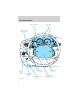
Controls and features • Place the provided height adaptors onto the back of the GARAGE control as needed. • Press the GARAGE control to activate the transmitter. Electronic compass/temperature display Outside air temperature The outside temperature display is contained in the overhead console. The temperature display can be turned off and on by pressing the SELECT control on the overhead console. The temperature can be displayed in Centigrade or Fahrenheit by pressing the SELECT control.
Controls and features accuracy. Adjustments may need to be made to the zone and calibration of the compass. Compass zone adjustment 1. Determine which magnetic zone you are in by referring to the zone map. 1 15 2 14 3 13 4 12 11 5 6 10 7 2. Press and hold the SELECT control until VAR appears in the display, then release. The display should show the current zone number. 3. Press the SELECT control until the desired zone number appears. The display will flash and then return to normal operation.
Controls and features Compass calibration adjustment Perform this adjustment in an open area free from steel structures and high voltage lines: • Press and hold the SELECT control until CAL appears in the display (approximately eight seconds) and release. • Drive the vehicle slowly (less than 5 km/h [3 mph]) in circles until CAL indicator turns off in about 2–3 complete circles. • The compass is now calibrated. CAL Interior Lamps Map lamps To turn on the map lamps, press the control next to each lamp.
Controls and features Courtesy/reading lamps The courtesy lamp lights when: • any door is opened. • the instrument panel dimmer switch is held up until the courtesy lamps come on. • the remote entry controls are pressed and the ignition is OFF. The reading lamps can be turned on by pressing the rocker controls next to each lamp. Rear door lamps The rear door lamps lights when: • any door is opened. • the instrument panel dimmer switch is held up until the courtesy lamps come on.
Controls and features Do not let children play with the moon roof. They may seriously hurt themselves. POWER WINDOWS Press and hold the rocker switches to open and close windows. • Press the top portion of the rocker switch to close. AUTO • Press the bottom portion of the rocker switch to open. AUTO One touch down • Press AUTO completely down and release quickly. The driver’s window will open fully. Depress again to stop window operation.
Controls and features Accessory delay (if equipped) With accessory delay, the window switches may be used for up to ten minutes after the ignition switch is turned to the OFF position or until any door is opened. POWER DOOR LOCKS Press U to unlock all doors and L to lock all doors. L U CHILDPROOF DOOR LOCKS When these locks are set, the rear doors cannot be opened from the inside. The rear doors can be opened from the outside when the doors are unlocked.
Controls and features POWER SIDE VIEW MIRRORS The ignition can be in any position to adjust the power side view mirrors. To adjust your mirrors: 1. Select L to adjust the left mirror or R to adjust the right mirror. MIRRORS L 2. Move the control in the direction you wish to tilt the mirror. MIRRORS L R 3. Return to the center position to lock mirrors in place. Signal mirrors (if equipped) When the turn signal is activated, the outer portion of the appropriate mirror housing will blink red.
Controls and features Fold-away mirrors Pull the side mirrors in carefully when driving through a narrow space, like an automatic car wash. POSITIVE RETENTION FLOOR MAT Position the floor mat so that the eyelet is over the pointed end of the retention post and rotate forward to lock in. Make sure that the mat does not interfere with the operation of the accelerator or the brake pedal. To remove the floor mat, reverse the installation procedure.
Controls and features TAILGATE REMOVAL Your tailgate is removable to allow more room for loading. 1. Lower the tailgate. 2. Use a screwdriver to pry the spring clip (on each connector) past the head of the support screw. Disconnect cable. 3. Disconnect the other cable. 4. Lift tailgate to a 45 degree angle. 5. Lift right side off of its hinge. 6. Lift left side off of its hinge. To install, follow the removal procedures in reverse order.
Controls and features 4. Evenly push down on the extender and push the round knobs in on each side locking it in place. To stow the bed extender, follow steps one through four in reverse order. The bed extender may be used to secure a load of up to 46 kg (100 lbs.) on the tailgate. The bed extender should always be kept in the stowed position with the tailgate closed when not in use. To remove the bed extender: 1. Extend the bed extender. 2. Pull the round knobs on each side of the extender to unlock it.
Controls and features SECURILOCKY PASSIVE ANTI-THEFT SYSTEM Your vehicle is equipped with a coded-key anti-theft system. Only the correct key will be able to start your vehicle. If your keys are lost or stolen, you must take your vehicle to your dealership for key reprogramming. This system provides an advanced level of vehicle theft protection. Your vehicle’s engine can only be started with the two coded keys provided with your vehicle.
Controls and features Theft indicator The theft indicator in the instrument cluster will operate as follows: • When the ignition is OFF, the theft indicator will flash briefly every two seconds to indicate the anti-theft system is protecting your vehicle. • When the ignition is turned to ON or START, the theft indicator will light for three seconds and then go out.
Controls and features 4. Turn the ignition to OFF and remove the second coded key from the ignition. 5. Within 10 seconds of turning the ignition to OFF, insert the new unprogrammed key (new key/valet key) into the ignition and turn the ignition from OFF to ON (maintain ignition in ON for at least one second). This step will program your new key to a coded key. 6. To program additional new unprogrammed key(s), repeat this procedure from step 1.
Controls and features Unlocking the doors Press this control to unlock the driver’s door. The interior lamps will illuminate. Press the control a second time within three seconds to unlock all doors. Locking the doors Press this control to lock all doors. To confirm doors are closed and locked, press this control a second time within three seconds. The door(s) will lock again, the horn will chirp once and the lamps will flash.
Controls and features Changes or modifications not expressly approved by the party responsible for compliance could void the user’s authority to operate the equipment. Replacing the battery The remote transmitter is powered by one coin type three-volt lithium battery CR2032 or equivalent. Typical operating range will allow you to be up to 10 meters (33 feet) away from your vehicle.
Controls and features Replacing lost transmitters If a remote transmitter has been lost and you would like to remove it from the vehicle’s memory, or you would like to purchase additional remote transmitters and have them programmed to your vehicle: • Take all your vehicle’s transmitters to your dealer for programming, or • Perform the programming procedure yourself Programming remote transmitters It is necessary to have all (maximum of four — original and/or new) of your remote transmitters available prio
Controls and features Reprogramming transmitters Your dealer will be able to reprogram remote transmitter(s) to your vehicle. Installation of a new battery to your remote transmitter does not cause the remote transmitter to become deprogrammed.
Controls and features Illuminated entry The illuminated entry system will turn on the interior lights when the remote transmitter unlock control is pressed. The illuminated entry system will turn off the interior lights if the ignition switch is turned to the ON position, or if the remote transmitter lock control is pressed, or after 25 seconds of illumination. The inside lights will not turn off if: • they have been turned on with the dimmer control or • any door is open.
Controls and features Your personal code does not replace the permanent code that the dealership gave you. You can use either code to unlock your vehicle. If a second personal code is entered, the module will erase it in favor of the new code. If you wish to erase your personal code, use the following instructions: 1. Enter factory set code. 2. Press 1/2 control within five seconds of step one. 1 2 3 4 5 6 7 8 9 0 3. Press 7/8 control and 9/0 control at the same time within five seconds of step 2.
Seating and safety restraints SEATING Adjusting the front manual seat Never adjust the driver’s seat or seatback when the vehicle is moving. Do not pile cargo higher than the seatbacks to reduce the risk of injuring people in a collision or sudden stop. Always drive and ride with your seatback upright and the lap belt snug and low across the hips. Reclining the seatback can reduce the effectiveness of the seat’s safety belt in the event of a collision. Lift handle to move seat forward or backward.
Seating and safety restraints 60/40 split bench seat (if equipped) • Lift the release bar to move the seat forward or backward. Ensure the seat is relatched into place. • Pull the seatback handle up to recline the seat. • Push down the release lever located on the back of the seat to quickly fold the seatback forward. Captain’s chair (if equipped) • Lift the track release bar to move the seat forward or rearward. Make sure that the seat is relatched into place.
Seating and safety restraints Do not pile cargo higher than the seatbacks to avoid injuring people in a collision or sudden stop. Always drive and ride with your seatback upright and the lap belt snug and low across the hips. Reclining the seatback can reduce the effectiveness of the seat’s safety belt in the event of a collision. The control is located on the outboard side of the seat cushion. Press front to raise or lower the front portion of the seat cushion.
Seating and safety restraints Using the manual lumbar support Turn the lumbar support control toward the front of vehicle to move the lumbar support forward for more direct support. Turn the lumbar support control toward the rear of vehicle to move the lumbar support back for less direct support. Folding down the rear seats The rear seatback has a split 60/40 seat. Each seat can be folded down into the load floor position. 1. Pull control to release seat.
Seating and safety restraints 2. Pull seatback toward front seat and down into load floor position. 3. Make sure seat is pushed all the way down and locks into position. Returning the seat to seating position Always be sure that the seat is in a latched position, whether the seat is occupied or empty. If not latched, the seat may cause injury during a sudden stop.
Seating and safety restraints 1. Pull control on the side of the seat to release seat cushion from the load floor position. 2. Lift seatback up until it locks into vertical position.
Seating and safety restraints Using the armrest (if equipped) Push the release control to move the armrest up or down. SAFETY RESTRAINTS Safety restraints precautions Always drive and ride with your seatback upright and the lap belt snug and low across the hips. To reduce the risk of injury, make sure children sit where they can be properly restrained. Never let a passenger hold a child on his or her lap while the vehicle is moving. The passenger cannot protect the child from injury in a collision.
Seating and safety restraints It is extremely dangerous to ride in a cargo area, inside or outside of a vehicle. In a collision, people riding in these areas are more likely to be seriously injured or killed. Do not allow people to ride in any area of your vehicle that is not equipped with seats and safety belts. Be sure everyone in your vehicle is in a seat and using a safety belt properly. In a rollover crash, an unbelted person is significantly more likely to die than a person wearing a seat belt.
Seating and safety restraints 2. To unfasten, push the release button and remove the tongue from the buckle. The front and rear outboard safety restraints in the vehicle are combination lap and shoulder belts. The front passenger and rear seat outboard safety belts have two types of locking modes described below: Vehicle sensitive mode The vehicle sensitive mode is the normal retractor mode, allowing free shoulder belt length adjustment to your movements and locking in response to vehicle movement.
Seating and safety restraints How to use the automatic locking mode • Buckle the combination lap and shoulder belt. • Grasp the shoulder portion and pull downward until the entire belt is extracted. • Allow the belt to retract. As the belt retracts, you will hear a clicking sound. This indicates the safety belt is now in the automatic locking mode.
Seating and safety restraints The safety belt pretensioner is a device which removes excess webbing from the safety belt system. The safety belt pretensioner uses the same crash sensor system as the front air bag supplemental restraint system (SRS). When the safety belt pretensioner deploys, webbing from the lap and shoulder belt is tightened.
Seating and safety restraints Lap belts Adjusting the lap belt The lap belts should fit snugly and as low as possible around the hips, not around the waist. • 1st row center seating position The lap belt does not adjust automatically. Insert the tongue into the correct buckle (the buckle closest to the direction the tongue is coming from). To lengthen the belt, turn the tongue at a right angle to the belt and pull across your lap until it reaches the buckle.
Seating and safety restraints The belt should fit snugly and as low as possible around your hips. Do not wear the lap belt around your waist. Safety belt extension assembly If the safety belt assembly is too short, even when fully extended, 20 cm (8 inches) can be added to the safety belt assembly by adding a safety belt extension assembly (part number 611C22). Safety belt extension assemblies can be obtained from your dealer at no cost.
Seating and safety restraints Belt minder The Belt Minder feature is a supplemental warning to the safety belt warning function. This feature provides additional reminders to the driver that the driver’s safety belt is unbuckled by intermittently sounding a chime and illuminating the safety belt warning lamp in the instrument cluster. If... The driver’s safety belt is not buckled approximately 5 seconds after the safety belt warning light has turned off...
Seating and safety restraints The following are reasons most often given for not wearing safety belts: (All statistics based on U.S. data) Reasons given... 9Crashes are rare events9 Consider... 36 700 crashes occur every day. The more we drive, the more we are exposed to 9rare9 events, even for good drivers. 1 in 4 of us will be seriously injured in a crash during our lifetime. 9I’m not going far9 3 of 4 fatal crashes occur within 25 miles of home.
Seating and safety restraints One time disable Anytime the safety belt is buckled and then unbuckled during an ignition ON cycle, Belt Minder will be disabled for that ignition cycle only. Deactivating/activating the belt minder feature Read steps 1 - 9 thoroughly before proceeding with the deactivation/activation programming procedure.
Seating and safety restraints 6. Within seven seconds of the safety belt warning light turning off, buckle then unbuckle the safety belt. • This will disable Belt Minder if it is currently enabled, or enable Belt Minder if it is currently disabled. 7. Confirmation of disabling Belt Minder is provided by flashing the safety belt warning light four times per second for three seconds. 8.
Seating and safety restraints AIR BAG SUPPLEMENTAL RESTRAINT SYSTEM (SRS) LOW FUEL H 40 F E 18 8 H 10 50 60 80 100 70 3 60 30 20 DOOR AJAR BRAKE 40 000000 120 80 140 90 20 160 MPH 0 0 P R N 0 km/h 21 2 THEFT 4 VOL - PUSH ON 5 1 CHECK SUSP 100 ABS FM1 AM FM IVE RDR OVE 6 RPMx1000 BASS ST TREB BAL FADE AUTO SET CHECK ENGINE SEEK SCAN TUNE EJ w f DOLBY B NR TAPE CD DISCS P PULL FOR FOG PANEL DIM REW FF 1 SIDE 1-2 2 3 COMP 4 SHUFFLE 5 6 RES ON
Seating and safety restraints Always transport children 12 years old and under in the back seat and always properly use appropriate child restraints. National Highway Traffic Safety Administration (NHTSA) recommends a minimum distance of at least 25 cm (10 inches) between an occupant’s chest and the driver air bag module. Never place your arm over the air bag module as a deploying air bag can result in serious arm fractures or other injuries.
Seating and safety restraints Additional equipment such as snowplow equipment may effect the performance of the air bag sensors increasing the risk of injury. Please refer to the Body Builders Layout Book for instructions about the appropriate installation of additional equipment. Children and air bags For additional important safety information, read all information on safety restraints in this guide. Children must always be properly restrained.
Seating and safety restraints cause activation. Air bags are designed to inflate in frontal and near-frontal collisions, not rollover, side-impact, or rear-impacts unless the collision causes sufficient longitudinal deceleration. The air bags inflate and deflate rapidly upon activation. After air bag deployment, it is normal to notice a smoke-like, powdery residue or smell the burnt propellant. This may consist of cornstarch, talcum powder (to lubricate the bag) or sodium compounds (e.g.
Seating and safety restraints • one or more impact and safing sensors and diagnostic monitor (RCM), • a readiness light and tone, • and the electrical wiring which connects the components. The RCM (restraints control module) monitors its own internal circuits and the supplemental air bag electrical system warning (including the impact sensors, the system wiring, the air bag system readiness light, the air bag back up power and the air bag ignitors).
Seating and safety restraints Important child restraint precautions You are required by law to use safety restraints for children in the U.S. and Canada. If small children ride in your vehicle (generally children who are four years old or younger and who weigh 18 kg [40 lbs] or less), you must put them in safety seats made especially for children. Check your local and state or provincial laws for specific requirements regarding the safety of children in your vehicle.
Seating and safety restraints A belt-positioning booster should be used if the shoulder belt rests in front of the child’s face or neck, or if the lap belt does not fit snugly on both thighs, or if the thighs are too short to let the child sit all the way back on the seat cushion when the lower legs hang over the edge of the seat cushion. You may wish to discuss the special needs of your child with your pediatrician.
Seating and safety restraints • Keep the buckle release button pointing up and away from the safety seat, with the tongue between the child seat and the release button, to prevent accidental unbuckling. • Place seat back in upright position. • Put the safety belt in the automatic locking mode. Refer to Automatic locking mode (passenger side front and outboard rear seating positions) (if equipped). Ford recommends the use of a child safety seat having a top tether strap.
Seating and safety restraints 2. Pull down on the shoulder belt and then grasp the shoulder belt and lap belt together. 3. While holding the shoulder and lap belt portions together, route the tongue through the child seat according to the child seat manufacturer’s instructions. Be sure the belt webbing is not twisted. 4. Insert the belt tongue into the proper buckle (the buckle closest to the direction the tongue is coming from) for that seating position until you hear a snap and feel the latch engage.
Seating and safety restraints 5. To put the retractor in the automatic locking mode, grasp the shoulder portion of the belt and pull downward until all of the belt is extracted and a click is heard. 6. Allow the belt to retract. The belt will click as it retracts to indicate it is in the automatic locking mode. 7. Pull the lap belt portion across the child seat toward the buckle and pull up on the shoulder belt while pushing down with your knee on the child seat. 8.
Seating and safety restraints Installing child safety seats in the front row lap belt seating positions 1. Lengthen the lap belt. To lengthen the belt, hold the tongue so that its bottom is perpendicular to the direction of webbing while sliding the tongue up the webbing. 2. Place the child safety seat in the center seating position. 3. Route the tongue and webbing through the child seat according to the child seat manufacturer’s instructions. 4.
Seating and safety restraints 8. Before placing the child in the seat, forcibly tilt the seat forward and back to make sure the seat is securely held in place. 9. Check to make sure the child seat is properly secured before each use. Attaching child safety seats with tether straps Most new forward-facing child safety seats include a tether strap which goes over the back of the seat and hooks to an anchoring point. Tether straps are available as an accessory for many older safety seats.
Seating and safety restraints • You may need to pull the seatback forward to access the tether anchors. Make sure the seat is locked in the upright position before installing the child seat. Refer to the Folding Down The Rear Seats section in this chapter for information on how to operate the rear seats. 4. Clip the tether strap to the anchor as shown. If the tether strap is clipped incorrectly, the child safety seat may not be retained properly in the event of a collision. 5.
Starting PREPARING TO START YOUR VEHICLE Engine starting is controlled by the powertrain control system. This system meets all Canadian Interference-Causing Equipment standard requirements regulating the impulse electrical field strength of radio noise. When starting a fuel-injected engine, avoid pressing the accelerator before or during starting. Only use the accelerator when you have difficulty starting the engine. For more information on starting the vehicle, refer to Starting the engine in this chapter.
Starting • Make sure the parking brake is set. • Make sure the gearshift is in P (Park). HOOD BRAKE 3. Turn the key to 4 (ON) without turning the key to 5 (START). 4 If there is difficulty in turning the 3 key, firmly rotate the steering wheel 5 left and right until the key turns freely.
Starting STARTING THE ENGINE 1. Turn the key to 5 (START) without pressing the accelerator pedal and release as soon as the engine starts. The key will return to 4 (ON). 2. If the temperature is above –12°C (10°F) and the engine does not start within five seconds on the first try, turn the key to OFF, wait 10 seconds and try again. 4 3 5 2 1 3. If the temperature is below -12° C (10° F) and the engine does not start in 15 seconds on the first try, turn the key OFF and wait 10 seconds and try again.
Starting Guarding against exhaust fumes Although odorless and colorless, carbon monoxide is present in exhaust fumes. Take precautions to avoid its dangerous effects. If you ever smell exhaust fumes of any kind inside your vehicle, have your dealer inspect and fix your vehicle immediately. Do not drive if you smell exhaust fumes. These fumes are harmful and could kill you. Have the exhaust and body ventilation systems checked whenever: • the vehicle is raised for service.
Driving BRAKES Your service brakes are self-adjusting. Refer to the scheduled maintenance guide for scheduled maintenance. Occasional brake noise is normal and often does not indicate a performance concern with the vehicle’s brake system. In normal operation, automotive brake systems may emit occasional or intermittent squeal or groan noises when the brakes are applied.
Driving ABS warning lamp ABS The ABS warning lamp in the instrument cluster momentarily illuminates when the ignition is turned to the ON position. If the light does not illuminate momentarily at start up, remains on or continues to flash, the ABS needs to be serviced. With the ABS light on, the anti-lock brake system is disabled and normal BRAKE braking is still effective unless the ! brake warning light also remains illuminated with parking brake released.
Driving Parking brake Apply the parking brake whenever the vehicle is parked. To set the parking brake, press the parking brake pedal down until the pedal stops. HOOD BRAKE The BRAKE warning lamp in the instrument cluster illuminates and remains illuminated (when the ignition is turned ON) until the parking brake is released. BRAKE ! Always set the parking brake fully and make sure that the gearshift is securely latched in P (Park) (automatic transmission) or in 1 (First) (manual transmission).
Driving Pull the release lever to release the brake. Driving with the parking brake on will cause the brakes to wear out quickly and reduce fuel economy. HOOD BRAKE TRACTION-LOK AXLE (IF EQUIPPED) This axle provides added traction on slippery surfaces, particularly when one wheel is on a poor traction surface. Under normal conditions, the Traction-Lok axle functions like a standard rear axle.
Driving If the steering wanders or pulls, the condition could be caused by any of the following: • underinflated tire(s) on any wheel(s) • high crown in center of road • high crosswinds • wheels out of alignment • loose or worn components in steering linkage PREPARING TO DRIVE YOUR VEHICLE Utility vehicles have a significantly higher rollover rate than other types of vehicles. In a rollover crash, an unbelted person is significantly more likely to die than a person wearing a seat belt.
Driving Use extra caution while becoming familiar with your vehicle. Know the capabilities and limitations of both you as a driver and your vehicle. AUTOMATIC TRANSMISSION OPERATION Brake-shift interlock This vehicle is equipped with a brake-shift interlock feature that prevents the gearshift lever from being moved from P (Park) when the ignition is in the ON position unless brake pedal is depressed.
Driving If the parking brake is fully released, but the brake warning lamp remains illuminated, the brakes may not be working properly. See your dealer or a qualified service technician. Driving with a 4–speed automatic transmission Understanding gearshift positions To put your vehicle in gear, start the engine, depress the brake pedal, then move gearshift lever out of P (Park). Hold the brake pedal down while you move the gearshift lever from P (Park) to another position.
Driving (Overdrive) The normal driving position for the best fuel economy. Transmission operates in gears one through four. (Overdrive) can be deactivated by pressing the transmission control switch (TCS) on the end of the gearshift lever. The transmission control indicator light (TCIL) (the word OFF) on the end of the gearshift lever will illuminate. OVERDRIVE OFF OVERDRIVE Drive – Not shown on the display.
Driving 1 (First) Use 1 (Low) to provide maximum engine braking on steep downgrades. Upshifts can be made by shifting to 2 (Second) or to (Overdrive). Selecting 1 (Low) at higher speeds causes the transmission to shift to a lower gear, and will shift to 1 (Low) after vehicle decelerates to the proper speed. Forced Downshifts To gain acceleration in (Overdrive) or Drive (O/D OFF) when passing another vehicle, push the accelerator to the floor.
Driving • 4X4 —momentarily illuminates when the ignition is turned to the ON position. Illuminates when 4H (4WD High) is engaged. • LOW RANGE —momentarily illuminates when the ignition is turned to the ON position. Illuminates when 4L (4WD Low) is engaged. 4x4 LOW RANGE Using the electronic shift 4WD system Positions of the electronic shift system 2H (2WD High) – Power to rear axle only. 4H (4WD High) – Power delivered to front and rear axles for increased traction.
Driving Shifting from 4H (4WD high) to 2H (2WD high) Move the 4WD control to 2H at any forward speed. 4H 2H Shifting between 4H (4WD high) and 4L (4WD low) 1. Bring the vehicle to a stop. 2. Depress the brake. 3. Place the gearshift in N (Neutral). 4. Move the 4WD control to the 4H 4H or 4L position.
Driving You should either know the terrain or examine maps of the area before driving. Map out your route before driving in the area. For more information on driving off-road, read the “Four Wheeling” supplement in your owner’s portfolio. If your vehicle gets stuck If the vehicle is stuck it may be rocked out by shifting from forward and reverse gears, stopping between shifts, in a steady pattern. Press lightly on the accelerator in each gear.
Driving Water intrusion into the transmission may damage the transmission. Replace rear axle lubricant any time the axle has been submerged in water. The rear axle does not normally require a lubricant change for the life of the vehicle. Rear axle lubricant quantities are not to be checked or changed unless a leak is suspected or repair is required. Driving on hilly or sloping terrain When driving on a hill, avoid driving crosswise or turning on steep slopes. You could lose traction and slip sideways.
Driving Allow more stopping distance and drive slower than usual. Consider using one of the lower gears. VEHICLE LOADING Before loading a vehicle, familiarize yourself with the following terms: • Base Curb Weight: Weight of the vehicle including any standard equipment, fluids, lubricants, etc. It does not include passengers or aftermarket equipment. • Payload: Combined maximum allowable weight of cargo, passengers and optional equipment.
Driving Remember to figure in the tongue load of your loaded trailer when figuring the total weight. Do not exceed the GVWR or the GAWR specified on the certification label. Do not use replacement tires with lower load carrying capacities than the originals because they may lower the vehicle’s GVWR and GAWR limitations. Replacement tires with a higher limit than the originals do not increase the GVWR and GAWR limitations.
Driving Your vehicle has the capability to haul more cargo and people than most passenger cars. Depending upon the type and placement of the load, hauling cargo and people may raise the center of gravity of the vehicle. Calculating the load your vehicle can carry/tow 1. Use the appropriate maximum gross combined weight rating (GCWR) chart to find the maximum GCWR for your type engine and rear axle ratio. 2. Weigh your vehicle as you customarily operate the vehicle without cargo.
Driving Towing a trailer places an additional load on your vehicle’s engine, transmission, axle, brakes, tires and suspension. Inspect these components carefully after any towing operation. Exceeding the maximum GCWR could result in extensive damage to your vehicle and personal injury. Do not exceed the GVWR or the GAWR specified on the certification label.
Driving Trailer frontal area considerations: • Not to exceed towing vehicle front area without Class III trailer towing package • Not to exceed 5.52 square meters (60 square feet) with Class III trailer towing package Trailer frontal area considerations: • Not to exceed towing vehicle front area without Class III trailer towing package • Not to exceed 5.
Driving Safety chains Always connect the trailer’s safety chains to the frame or hook retainers of the vehicle. To connect the trailer’s safety chains, cross the chains under the trailer tongue and allow slack for turning corners. If you use a rental trailer, follow the instructions that the rental agency gives to you. Do not attach safety chains to the bumper.
Driving • Consult your local motor vehicle speed regulations for towing a trailer. • Use a lower gear when towing up or down steep hills. This will eliminate excessive downshifting and upshifting for optimum fuel economy and transmission cooling. • Anticipate stops and brake gradually. Exceeding the GCWR rating may cause internal transmission damage and void your warranty coverage. Servicing after towing If you tow a trailer for long distances, your vehicle will require more frequent service intervals.
Driving Replace the rear axle lubricant anytime the axle has been submerged in water. Rear axle lubricant quantities are not to be checked or changed unless a leak is suspected or repair required. Disconnect the wiring to the trailer before backing the trailer into the water. Reconnect the wiring to the trailer after the trailer is removed from the water. Recreational towing (all wheels on the ground) An example of recreational towing would be towing your vehicle behind a Motorhome.
Roadside emergencies GETTING ROADSIDE ASSISTANCE To fully assist you should you have a vehicle concern, Ford offers a complimentary roadside assistance program. This program is separate from the New Vehicle Limited Warranty. The service is available: • 24–hours, seven days a week • for the Basic warranty period (Canada) or New Vehicle Limited Warranty period (U.S.
Roadside emergencies Roadside coverage beyond basic warranty In the United States, you may purchase additional roadside assistance coverage beyond this period through the Ford Auto Club by contacting your Ford or Lincoln Mercury dealer. Similarly in Canada, you may purchase additional coverage beyond the basic coverage period by consulting the Ford Roadside Assistance Club brochure or by calling 1–877–294–CLUB (1–877–894–2582).
Roadside emergencies The fuel pump shut-off switch is located in the passenger’s foot well, by the kick panel. Use the following procedure to reset the fuel pump shut-off switch. 1. Turn the ignition to the OFF position. 2. Check the fuel system for leaks. 3. If no fuel leak is apparent, reset the fuel pump shut-off switch by pushing in on the reset button. 4. Turn the ignition to the ON position. Pause for a few seconds and return the key to the OFF position. 5.
Roadside emergencies Always replace a fuse with one that has the specified amperage rating. Using a fuse with a higher amperage rating can cause severe wire damage and could start a fire. Standard fuse amperage rating and color COLOR Fuse Rating Mini Fuses Standard Fuses Maxi Fuses 2A 3A 4A 5A 7.
20 21 10 11 31 30 9 RELAY 5 29 19 8 28 18 RELAY 4 7 27 17 RELAY 3 RELAY 2 RELAY 1 6 16 5 26 15 4 25 14 13 2 3 12 FUSE1 22 23 24 Roadside emergencies The fuses are coded as follows.
Roadside emergencies Fuse/Relay Location 11 12 13 14 15 16 17 18 19 20 21 22 23 24 25 26 27 28 Fuse Amp Passenger Compartment Rating Fuse Panel Description 30A Front Washer Pump Relay, Wiper Run/Park Relay, Wiper Hi/LO Relay, Windshield Wiper Motor — Not Used 20A Stop Lamp Switch (Lamps), Turn/Hazard Flasher, Speed Control Module 15A Battery Saver Relay, Interior Lamp Relay, Accessory Delay Relay (Power Windows) 5A Stop Lamp Switch, (Speed Control, Brake Shift Interlock, ABS, PCM Module Inputs), GEM Mod
Roadside emergencies Fuse/Relay Location 29 30 31 Relay Relay Relay Relay Relay 1 2 3 4 5 Fuse Amp Passenger Compartment Rating Fuse Panel Description 5A Autolamp Module, Transmission Overdrive Control Switch 30A Passive Anti Theft Transceiver, Cluster, Ignition Coils, Powertrain Control Module Relay — Not Used — Interior Lamp Relay — Battery Saver Relay — Not Used — One Touch Down Window Relay — ACC Delay Relay Power distribution box The power distribution box is located in the engine compartment.
Fuse/Relay Location 1 2 3 4 5 6 Fuse Amp Rating 20A * 30A* 30A* — 20A* 15A* 7 8 9 10 11 12 13 14 15 16 20A* — 15A* 20A* 20A* 20A* 15A* — — — FUSE 1 FUSE 2 FUSE 3 FUSE 4 FUSE 5 FUSE 6 FUSE 7 FUSE 8 FUSE 9 FUSE 10 FUSE 11 FUSE 12 FUSE 13 FUSE 14 FUSE 15 FUSE 16 FUSE 17 FUSE 18 FULL RELAY 301 MAXI FUSE 108 MAXI FUSE 107 MAXI FUSE 104 MAXI FUSE 112 MAXI FUSE 111 MAXI FUSE 103 MAXI FUSE 116 HALF RELAY 202 MAXI FUSE 102 MAXI FUSE 101 MAXI FUSE 110 MAXI FUSE 114 MAXI FUSE 118 MAXI FUSE 106
Roadside emergencies Fuse/Relay Location 17 18 19 20 21 22 23 24 101 102 103 104 105 106 107 108 109 110 111 112 113 114 115 116 117 118 201 136 Fuse Amp Power Distribution Box Description Rating — Not Used 15A* Powertrain Control Module, Fuel Injectors, Fuel Pump Relay, Idle Air Control, Mass Air Flow Sensor 10A* Trailer Tow Stop and Right Turn Lamp 10A* Trailer Tow Stop and Left Turn Lamp — Not Used — Not Used 15A* HEGO Sensor, Canister Vent, Automatic Transmission, CMS Sensor — Not Used 30A** Trailer T
Roadside emergencies Fuse/Relay Fuse Amp Location Rating 202 — 203 — 204 — 205 — 206 — 207 — 208 — 209 — 301 — 302 — 303 — 304 — 305 — 306 — 401 — 501 — 502 — 503 — 601 30A CB 602 — *Mini fuses **Maxi fuses Power Distribution Box Description Front Wiper Run/Park Relay Trailer Tow Backup Lamp Relay A/C Clutch Relay Horn Relay Fog Lamp Relay Front Washer Pump Relay Not Used Front Wiper Hi/Lo Relay Fuel Pump Relay Trailer Tow Battery Charge Relay Not Used Powertrain Control Module Relay Not Used Not Used Not
Roadside emergencies If your vehicle is equipped with 4WD, a spare tire of a different size than the road tires should not be used. Such a tire could result in damage to driveline components and make the vehicle difficult to control.
Roadside emergencies Stowing the spare tire 1. Lay the tire on the ground with the valve stem facing up. 2. Slide the wheel under the vehicle and install the retainer through the wheel center. 3. Turn the jack handle clockwise until the tire is raised to its original position underneath the vehicle. The jack handle ratchets when the tire is raised to the stowed position. It will not allow you to overtighten.
Roadside emergencies 3. Block the diagonally opposite wheel. 4. Obtain the spare tire and jack from their storage locations. 5. Use the tip of the lug wrench to remove any wheel trim. 6. Loosen each wheel lug nut one-half turn counterclockwise but do not remove them until the wheel is raised off the ground. 7. Position the jack according to the following guides and turn the jack handle clockwise until the wheel is completely off the ground.
Roadside emergencies • Front (4x2) • Front (4x4) • Rear 141
Roadside emergencies To lessen the risk of personal injury, do not put any part of your body under the vehicle while changing a tire. Do not start the engine when your vehicle is on the jack. The jack is only meant for changing the tire. • Never use the front or rear differential as a jacking point. 8. Remove the lug nuts with the lug wrench. 9. Replace the flat tire with the spare tire, making sure the valve stem is facing outward. Reinstall the lug nuts until the wheel is snug against the hub.
Roadside emergencies Do not attempt to push start your vehicle. Automatic transmissions do not have push-start capability. Preparing your vehicle 1. Use only a 12–volt supply to start your vehicle. 2. Do not disconnect the battery of the disabled vehicle as this could damage the vehicle’s electrical system. 3. Park the booster vehicle close to the hood of the disabled vehicle making sure the two vehicles do not touch.
Roadside emergencies + + – – 2. Connect the other end of the positive (+) cable to the positive (+) terminal of the assisting battery. + + – – 3. Connect the negative (-) cable to the negative (-) terminal of the assisting battery. + + – – 4.
Roadside emergencies carburetor/fuel injection system. Do not use fuel lines, engine rocker covers or the intake manifold as grounding points. Do not connect the end of the second cable to the negative (-) terminal of the battery to be jumped. A spark may cause an explosion of the gases that surround the battery. 5. Ensure that the cables are clear of fan blades, belts, moving parts of both engines, or any fuel delivery system parts. Jump starting 1.
Roadside emergencies + + – – 2. Remove the jumper cable on the negative (-) connection of the booster vehicle’s battery. + + – – 3. Remove the jumper cable from the positive (+) terminal of the booster vehicle’s battery. + + – – 4. Remove the jumper cable from the positive (+) terminal of the disabled vehicle’s battery. After the disabled vehicle has been started and the jumper cables removed, allow it to idle for several minutes so the engine computer can relearn its idle conditions.
Roadside emergencies WRECKER TOWING If you need to have your vehicle towed, contact a professional towing service or, if you are a member, your roadside assistance center. It is recommended that your vehicle be towed with a wheel lift or flatbed equipment. Do not tow with a slingbelt. Ford Motor Company has not approved a slingbelt towing procedure. On 4x2 vehicles, it is acceptable to tow the vehicle with the front wheels on the ground (without dollies) and the rear wheels off the ground.
Maintenance and care SERVICE RECOMMENDATIONS To help you service your vehicle: • We highlight do-it-yourself items in the engine compartment for easy location. • We provide a Scheduled Maintenance Guide which makes tracking routine service easy. If your vehicle requires professional service, your dealership can provide necessary parts and service. Check your “Warranty Guide” to find out which parts and services are covered.
Maintenance and care Do not start your engine with the air cleaner removed and do not remove it while the engine is running. OPENING THE HOOD 1. Inside the vehicle, pull the hood release handle located under the bottom of the instrument panel. 2. Go to the front of the vehicle and release the auxiliary latch that is located under the front center of the hood. 3. Lift the hood until the lift cylinders hold it open.
Maintenance and care IDENTIFYING COMPONENTS IN THE ENGINE COMPARTMENT 4.6L V8 and 5.4L V8 engines 1 2 3 4 5 6 7 8 10 9 1. Battery 2. Automatic transmission fluid dipstick 3. Engine oil filler cap 4. Engine oil dipstick 5. Power steering fluid reservoir 6. Brake fluid reservoir 7. Power distribution box 8. Air filter assembly 9. Engine coolant reservoir 10.
Maintenance and care 2. Turn the engine off and wait a few minutes for the oil to drain into the oil pan. 3. Set the parking brake and ensure the gearshift is securely latched in P (Park). 4. Open the hood. Protect yourself from engine heat. 5. Locate and carefully remove the engine oil level indicator (dipstick). MIN MIN MAX MAX 6. Wipe the indicator clean. Insert the indicator fully, then remove it again. • If the oil level is between the MIN and MAX marks, the oil level is acceptable.
Maintenance and care • Oil levels above the MAX mark may cause engine damage. Some oil must be removed from the engine by a service technician. 7. Put the indicator back in and ensure it is fully seated. Adding engine oil 1. Check the engine oil. For instructions, refer to Checking the engine oil in this chapter. 2. If the engine oil level is not within the normal range, add only certified engine oil of the recommended viscosity.
Maintenance and care Change your engine oil and filter according to the appropriate schedule listed in the Scheduled Maintenance Guide. Ford production and aftermarket (Motorcraft) oil filters are designed for added engine protection and long life. If a replacement oil filter is used that does not meet Ford material and design specifications, start-up engine noises or knock may be experienced.
Maintenance and care If you use a brake fluid that is not DOT 3, you will cause permanent damage to your brakes. Do not let the fluid level in the reservoir for the master cylinder fall below the MIN mark. If master cylinder runs dry, this may cause the brakes to fail. WINDSHIELD WASHER FLUID Checking and adding washer fluid Check the washer fluid whenever you stop for fuel. The reservoir is highlighted with a symbol. If the level is low, add enough fluid to fill the reservoir.
Maintenance and care Canada, Motorcraft CXC-10), or an equivalent premium engine coolant that meets Ford specification ESE-M97B44-A. A 50/50 mixture of distilled water and Ford Premium Engine Coolant provides: • maximum cooling system efficiency. • freeze protection down to -36° C (-34° F). • boiling protection up to 129° C (265° F). • protection against rust and other forms of corrosion. • an accurate temperature readout from the engine coolant gauge.
Maintenance and care If the engine coolant has not been checked at the recommended interval, the engine coolant reservoir may become low or empty. If the reservoir is low or empty, add engine coolant to the reservoir. Refer to Adding engine coolant in this chapter. Automotive fluids are not interchangeable; do not use engine coolant, antifreeze or windshield washer fluid outside of its specified function and vehicle location.
Maintenance and care Do not put engine coolant in the windshield washer fluid reservoir. If engine coolant is sprayed onto the windshield, it could make it difficult to see through the windshield. When the engine is cool, add a 50/50 mixture of engine coolant and distilled water to the engine coolant reservoir, until the coolant is at the “cold fill level” or within the “cold fill range” as listed in the engine coolant reservoir (depending upon application).
Maintenance and care Recycled engine coolant Ford Motor Company recommends the use of a recycled engine coolant produced by Ford-approved processes. Not all coolant recycling processes produce coolant which meets Ford specification ESE-M97B44-A. Use of a recycled engine coolant which does not meet the Ford specification may harm engine and cooling system components. Always dispose of used automotive fluids in a responsible manner.
Maintenance and care • decreased engine coolant concentrations below 40% will decrease the freeze protection characteristics of the engine coolant and may cause engine damage. • refer to the chart on the coolant container to ensure the coolant concentration in your vehicle will provide adequate protection at the temperatures in which you drive. Vehicles driven year-round in non-extreme climates should use a 50/50 mixture of engine coolant and distilled water for optimum cooling system and engine protection.
Maintenance and care Once the engine temperature cools, the engine can be re-started. Take your vehicle to a service facility as soon as possible to minimize engine damage. When fail-safe mode is activated You have limited engine power when in the fail-safe mode, so drive the vehicle with caution. The vehicle will not be able to maintain high speed operation and the engine will run rough. Remember that the engine is capable of completely shutting down automatically to prevent engine damage, therefore: 1.
Maintenance and care 2. While the engine idles, turn the steering wheel left and right several times. 3. Turn the engine off. 4. Check the fluid level in the reservoir. It should be between the MIN and MAX lines. Do not add fluid if the level is in this range. MAX MIN MAX MIN 5. If the fluid is low, add fluid in small amounts, continuously checking the level until it reaches the range between the MIN and MAX lines. Be sure to put the cap back on the reservoir.
Maintenance and care 3. With the parking brake engaged and your foot on the brake pedal, start the engine and move the gearshift lever through all of the gear ranges. Allow sufficient time for each gear to engage. 4. Latch the gearshift lever in P (Park) and leave the engine running. 5. Remove the dipstick, wiping it clean with a clean, dry lint free rag. If necessary, refer to Identifying components in the engine compartment in this chapter for the location of the dipstick. 6.
Maintenance and care High fluid level Fluid levels above the safe range may result in transmission failure. An overfill condition of transmission fluid may cause shift and/or engagement concerns and/or possible damage. High fluid levels can be caused by an overheating condition. DON’T ADD Adjusting automatic transmission fluid levels Before adding any fluid, make sure the correct type is used.
Maintenance and care Checking and adding transfer case fluid (if equipped) 1. Clean the filler plug. 2. Remove the filler plug and inspect the fluid level. 3. Add only enough fluid through the filler opening so that the fluid level is at the bottom of the opening. Use only fluid that meets Ford specifications. Refer to the Capacities and specifications chapter. DRIVELINE UNIVERSAL JOINT AND SLIP YOKE Your vehicle may be equipped with universal joints that require lubrication.
Maintenance and care BATTERY Your vehicle is equipped with a Motorcraft maintenance-free battery which normally does not require additional water during its life of service. However, for severe usage or in high temperature climates, check the battery electrolyte level. Refer to the Scheduled Maintenance Guide for the service interval schedules. Keep the electrolyte level in each cell up to the “level indicator”. Do not overfill the battery cells.
Maintenance and care When lifting a plastic-cased battery, excessive pressure on the end walls could cause acid to flow through the vent caps, resulting in personal injury and/or damage to the vehicle or battery. Lift the battery with a battery carrier or with your hands on opposite corners. Keep batteries out of reach of children. Batteries contain sulfuric acid. Avoid contact with skin, eyes or clothing. Shield your eyes when working near the battery to protect against possible splashing of acid solution.
Maintenance and care R TU LE AD RE N • Always dispose of automotive batteries in a responsible manner. Follow your local authorized standards for disposal. Call your local authorized recycling center to find out more about recycling automotive batteries. RECYCLE AIR FILTER MAINTENANCE Refer to the Scheduled Maintenance Guide for the appropriate intervals for changing the air filter element. When changing the air filter element, use only the Motorcraft air filter element listed.
Maintenance and care 2. Carefully separate the two halves of the air filter housing. 3. Remove the air filter element from the open end of the air filter housing. 4. Install a new air filter element, ensuring the arrow on the top half of the air filter housing lines up with the notch on the bottom half of air filter housing. Be careful not to crimp the filter element edges between the air filter housing. This could cause filter damage and allow unmetered air to enter the engine if not properly seated. 5.
Maintenance and care Changing the wiper blades To replace the wiper blades: 1. Pull the wiper arm away from the windshield and lock into the service position. 2. Turn the blade at an angle from the wiper arm. Push the lock pin manually to release the blade and pull the wiper blade down toward the windshield to remove it from the arm. 3. Attach the new wiper to the wiper arm and press it into place until a click is heard.
Maintenance and care Treadwear The treadwear grade is a comparative rating based on the wear rate of the tire when tested under controlled conditions on a specified government test course. For example, a tire graded 150 would wear one and one-half (1 1/2) times as well on the government course as a tire graded 100.
Maintenance and care SERVICING YOUR TIRES Checking the tire pressure • Use an accurate tire pressure gauge. • Check the tire pressure when tires are cold, after the vehicle has been parked for at least one hour or has been driven less than 5 km (3 miles). • Adjust tire pressure to recommended specifications found on the Certification Label inside of driver’s door. Improperly inflated tires can affect vehicle handling and can fail suddenly, possibly resulting in loss of vehicle control.
Maintenance and care • Five tire rotation Replacing the tires Replace the tires when the wear band is visible through the tire treads. When replacing full size tires, never mix radial bias-belted, or bias-type tires. Use only the tire sizes that are listed on the Certification Label. Make sure that all tires are the same size, speed rating, and load-carrying capacity. Use only the tire combinations recommended on the label.
Maintenance and care Do not replace your tires with “high performance” tires or larger size tires. Failure to follow these precautions may adversely affect the handling of the vehicle and make it easier for the driver to lose control and roll over. Tires that are larger or smaller than your vehicle’s original tires may also affect the accuracy of your speedometer. SNOW TIRES AND CHAINS Snow tires must be the same size and grade as the tires you currently have on your vehicle.
Maintenance and care WHAT YOU SHOULD KNOW ABOUT AUTOMOTIVE FUELS Important safety precautions Do not overfill the fuel tank. The pressure in an overfilled tank may cause leakage and lead to fuel spray and fire. The fuel system may be under pressure. If the fuel filler cap is venting vapor or if you hear a hissing sound, wait until it stops before completely removing the fuel filler cap. Otherwise, fuel may spray out and injure you or others.
Maintenance and care • Avoid inhaling fuel vapors. Inhaling too much fuel vapor of any kind can lead to eye and respiratory tract irritation. In severe cases, excessive or prolonged breathing of fuel vapor can cause serious illness and permanent injury. • Avoid getting fuel liquid in your eyes. If fuel is splashed in the eyes, remove contact lenses (if worn), flush with water for 15 minutes and seek medical attention. Failure to seek proper medical attention could lead to permanent injury.
Maintenance and care Choosing the right fuel Use only UNLEADED FUEL. The use of leaded fuel is prohibited by law and could damage your vehicle. Do not use fuel containing methanol. It can damage critical fuel system components. Your vehicle was not designed to use fuel or fuel additives with metallic compounds, including manganese-based compounds containing MMT. Repairs to correct the effects of using a fuel for which your vehicle was not designed may not be covered by your warranty.
Maintenance and care Cleaner air Ford approves the use of reformulated “cleaner-burning” gasolines to improve air quality. These gasolines may contain oxygenates up to 10% ethanol or 15% MTBE. Running out of fuel Avoid running out of fuel because this situation may have an adverse affect on powertrain components. If you have run out of fuel: • You may need to cycle the ignition from OFF to ON several times after refueling, to allow the fuel system to pump the fuel from the tank to the engine.
Maintenance and care The fuel system may be under pressure. If the fuel filler cap is venting vapor or if you hear a hissing sound, wait until it stops before completely removing the fuel filler cap. Otherwise, fuel may spray out and injure you or others. If you do not use the proper fuel filler cap, excessive pressure or vacuum in the fuel tank may damage the fuel system or cause the fuel system to work improperly in a collision, which may result in possible personal injury.
Maintenance and care The amount of empty reserve varies and should not be relied upon to increase driving range. When refueling your vehicle after the fuel gauge indicates empty, you might not be able to refuel the full amount of the advertised capacity of the fuel tank due to the empty reserve still present in the tank. For consistent results when filling the fuel tank: • Use the same filling rate setting (low — medium — high) each time the tank is filled. • Allow three automatic click-offs when filling.
Maintenance and care Driving style — good driving and fuel economy habits Give consideration to the lists that follow and you may be able to change a number of variables and improve your fuel economy. Habits • Smooth, moderate operation can yield up to 10% savings in fuel. • Steady speeds without stopping will usually give the best fuel economy. • Idling for long periods of time (greater than one minute) may waste fuel. • Anticipate stopping; slowing down may eliminate the need to stop.
Maintenance and care Conditions • Heavily loading a vehicle or towing a trailer may reduce fuel economy at any speed. • Carrying unnecessary weight may reduce fuel economy (approximately 0.4 km/L [1 mpg] is lost for every 180 kg [400 lb] of weight carried). • Adding certain accessories to your vehicle (for example bug deflectors, rollbars/light bars, running boards, ski/luggage racks) may reduce fuel economy. • To maximize the fuel economy, drive with the tonneau cover installed (if equipped).
Maintenance and care • Use only the specified fuel listed. • Avoid running out of fuel. • Do not turn off the ignition while your vehicle is moving, especially at high speeds. • Have the items listed in your Scheduled Maintenance Guide performed according to the specified schedule. The scheduled maintenance items listed in the Scheduled Maintenance Guide are essential to the life and performance of your vehicle and to its emissions system.
Maintenance and care Readiness for Inspection/Maintenance (I/M) testing In some localities, it may be a legal requirement to pass an I/M test of the on-board diagnostics system. If your “Check Engine/Service Engine Soon” light is on, refer to the description in the Warning Lights and Chimes section of the Instrumentation chapter. Your vehicle may not pass the I/M test with the “Check Engine/Service Engine Soon” light on.
Maintenance and care Replacing headlamp bulbs 1. Make sure that the headlamp control is in the OFF position. 2. Open the hood. 3. At the back of the headlamp, pull clips rearward and up (about 3⁄4 inch) to release the headlamp assembly. 4. Slide headlamp assembly forward and off of guide ribs to expose the back of the bulb and wiring connector. 5. Disconnect the electrical connector from the bulb by pulling rearward. 6.
Maintenance and care 11. Straighten alignment pins, making them parallel with the outer edges of the attachment standoff. 12. Carefully insert the headlamp assembly into the vehicle making sure the alignment pins are inserted into the proper holes and into the guide ribs. 13. Hold the headlamp assembly snugly against the vehicle and push down on the clips to lock the lamp into place. Replacing front parking lamp/turn signal bulbs 1. Remove screw from the lamp assembly. 2.
Maintenance and care 6. Align top and bottom ribs of parking lamp assembly with corresponding slots on front of vehicle. 7. Push gently until parking lamp assembly seats (you will hear a snap). 8. Install screw on lamp assembly. Replacing tail/brake/turn signal/backup lamp bulbs The tail/brake/turn signal and backup lamp bulbs are located in the tail lamp assembly, one just below the other. Follow the same steps to replace either bulb: 1. Open the liftgate to expose the lamp assembly screws. 2.
Maintenance and care Replacing high-mount brake and cargo lamp bulbs To remove the lamp assembly: 1. Remove the two screws and move the lamp assembly away from the vehicle to expose the bulb sockets. 2. Remove the bulb socket by rotating counterclockwise and pulling it out of the lamp assembly. 3. Pull the bulb straight out of the socket and push in the new bulb. To install the lamp assembly: 1. Install the bulb into the lamp assembly and rotate clockwise. 2.
Maintenance and care 3. Pull out the old bulb from the socket and push in the new bulb. 4. Install the bulb socket in lamp assembly by turning it clockwise. USING THE RIGHT BULBS Replacement bulbs are specified in the chart below. Headlamp bulbs must be marked with an authorized “D.O.T.” for North America and an “E” for Europe to assure lamp performance, light brightness and pattern and safe visibility.
Maintenance and care Washing your vehicle Wash your vehicle regularly with cold or lukewarm water. Never use strong detergents or soap. If your vehicle is particularly dirty, use a quality car wash detergent. Always use a clean sponge, washing glove or similar device and plenty of water for best results. To avoid spots, avoid washing when the hood is still warm, immediately after or during exposure to strong sunlight. During winter months, it is especially important to wash the vehicle on a regular basis.
Maintenance and care Waxing your vehicle Waxing your vehicle on a regular basis will reduce minor scratches and paint damage. Wax when water stops beading on the surface. This could be every three or four months, depending on operating conditions. Use only carnauba or synthetic-based waxes. Use a cleaning fluid with a clean cloth to remove any bugs before waxing your vehicle. Use tar remover to remove any tar spots. Avoid getting wax on the windshield, or on any surfaces which appear coarse or bumpy.
Maintenance and care Cleaning the engine Engines are more efficient when they are clean because grease and dirt buildup keep the engine warmer than normal. When washing: • Take care when using a power washer to clean the engine. The high pressure fluid could penetrate the sealed parts and cause damage. • Do not spray with cold water to avoid cracking the engine block or other engine components. • Never apply anything to the drive belt (including belt dressing).
Maintenance and care To avoid scratching the lamps, do not use a dry paper towel, chemical solvents or abrasive cleaners. Cleaning the wiper blades, windshield and rear window If the wiper blades do not wipe properly, clean the wiper blade rubber element with undiluted windshield washer solution or a mild detergent. To avoid damaging the blades, do not use fuel, kerosene, paint thinner or other solvents.
Maintenance and care Cleaning and maintaining the safety belts Clean the safety belts with a mild soap solution recommended for cleaning upholstery or carpets. Do not bleach or dye the belts, because these actions may weaken the belt webbing. Check the safety belt system periodically to make sure there are no nicks, wear or cuts. If your vehicle has been involved in an accident, refer to the Safety belt maintenance section in the Seating and safety restraints chapter.
Capacities and specifications MOTORCRAFT PART NUMBERS Component Air filter element Fuel filter Oil filter PCV valve Battery (standard) Battery (heavy duty) Spark plugs-platinum* 4.6L V8 engine FA-1634 FG-986B FL-820-S EV-233 BXT-59 BXT-65-650 AGSF-32P 5.4L V8 engine FA-1634 FG-986B FL-820-S EV-233 BXT-59 BXT-65-650 AWSF-22E * Refer to Vehicle Emissions Control Information (VECI) decal for spark plug gap information.
Capacities and specifications Fluid Ford Part Name Fuel tank N/A Power Motorcraft steering MERCONt fluid ATF Transfer Motorcraft case fluid MERCONt ATF Transmission Motorcraft fluid 3 MERCONtV ATF Front axle Motorcraft SAE 75W-90 Premium 4x4 Front Axle Lubricant Rear axle 5 Motorcraft SAE 75W-140 Synthetic Rear Axle Lubricant Windshield Ultra-Clear washer fluid Windshield Washer Concentrate Application Capacity All All 94.6L (25.0 gallons) Fill to line on reservoir 4x4 vehicles 1.9L (2.
Capacities and specifications correct type. Refer to your Scheduled Maintenance Guide to determine the correct service interval. Some transmission fluids may be labeled as dual usage, such as MERCONt and MERCONt V. These dual usage fluids are not to be used in an automatic transmission that requires use of the MERCONt type fluid. However, these dual usage fluids may be used in transmissions that require the MERCONt V type fluid. MERCONt and MERCONt V type fluids are not interchangeable.
Capacities and specifications LUBRICANT SPECIFICATIONS Item Front axle (4X4) Rear axle Brake fluid Engine coolant Engine oil Ford part name or equivalent Motorcraft SAE 75W-90 Premium 4x4 Front Axle Lubricant Motorcraft SAE 75W-140 High Performance Synthetic Rear Axle Lube 1 High Performance DOT 3 Motor Vehicle Brake Fluid Ford Premium Engine Coolant Motorcraft SAE 5W-30 Super Premium Motor Oil Multi-Purpose Grease Ford part number Ford specification XY-75W90-TQL WSP-M2C201-A F1TZ-19580-B WSL-M2C
Capacities and specifications Item Power steering and transfer case (4X4) Automatic transmission Windshield washer fluid 2 Ford part name or equivalent Motorcraft MERCONt ATF Motorcraft MERCONtV ATF Ultra-clear Windshield Washer Concentrate Ford part number Ford specification XT-2-QDX MERCONt XT-5-QM MERCONtV C9AZ-19550-AC ESR-M17P5-A 1 Add 118 ml (4 oz) of Additive Friction Modifier C8AZ-19B546-A or equivalent meeting Ford specification EST-M2C118-A for complete refill of Traction-Lok axles.
Capacities and specifications ENGINE DATA Engine Cubic inches Required fuel Firing order 4.6L V8 engine 281 87 octane 1-3-7-2-6-5-4-8 1.3-1.4 mm (0.052-0.056 inch) Coil on plug 9.0:1 Spark plug gap Ignition system Compression ratio 5.4L V8 engine 330 87 octane 1-3-7-2-6-5-4-8 1.3-1.4 mm (0.052-0.056 inch) Coil on plug 9.
Capacities and specifications 3 5 2 4 1 200
Capacities and specifications IDENTIFYING YOUR VEHICLE Certification label The National Highway Traffic Safety Administration Regulations require that a Certification Label be affixed to a vehicle and prescribe where the Certification Label may be located. The Certification Label is located on the front door latch pillar on the driver’s side. MFD. BY FORD MOTOR CO. IN U.S.A.
Customer assistance Ford Extended Service Plan You can get more protection for your new car or light truck by purchasing Ford Extended Service Plan (Ford ESP) coverage. Ford ESP is an optional service contract which is backed by Ford Motor Company or Ford Motor Service Company (in the U.S.) and Ford of Canada (in Canada).
Customer assistance If you have questions or concerns, or are unsatisfied with the service you are receiving, follow these steps: 1. Contact your Sales Representative or Service Advisor at your selling/servicing dealership. 2. If your inquiry or concern remains unresolved, contact the Sales Manager or Service Manager at the dealership. 3. If the inquiry or concern cannot be resolved at the dealership level, please contact the Ford Customer Assistance Center.
Customer assistance If you own a Lincoln vehicle and are away from home when your vehicle needs service, or if you need more help than the dealership could provide, after following the steps described above, contact the Ford Customer Assistance Center to find an authorized dealership to help you. In the United States: Ford Motor Company Customer Assistance Center 16800 Executive Plaza Drive P.O.
Customer assistance dispute handling procedure is not required prior to enforcing state created rights or other rights which are independent of the Magnuson-Moss Warranty Act or state replacement or repurchase laws. THE DISPUTE SETTLEMENT BOARD (U.S. only) The Dispute Settlement Board is: • an independent, third-party arbitration program for warranty disputes • available free to owners and lessees of qualifying Ford Motor Company vehicles The Dispute Settlement Board may not be available in all states.
Customer assistance is dependent upon the customer’s possession of the vehicle. Eligibility may differ according to state law. For example, see the unique brochures for California, West Virginia, Georgia and Wisconsin purchasers/lessees. Board membership The Board consists of: • three consumer representatives • a Ford or Lincoln Mercury dealership representative Consumer candidates for Board membership are recruited and trained by an independent consulting firm.
Customer assistance • a brief summary of the action taken by the dealer(s) and Ford Motor Company • the names (if known) of all the people you contacted at the dealership(s) • a description of the action you expect to resolve your concern You will receive a letter of explanation if your application does not qualify for Board review. Oral presentations If you would like to make an oral presentation, indicate YES to question #6 on the application.
Customer assistance You may also contact the North American Customer Assistance Center at 1-800-392-3673 (Ford), TDD for the hearing impaired: 1-800-232-5952 or by writing to the Center at the following address: Ford Motor Company Customer Assistance Center 16800 Executive Plaza Drive P.O.
Customer assistance The use of leaded fuel in your vehicle without proper conversion may damage the effectiveness of your emission control system and may cause engine knocking or serious engine damage. Ford Motor Company/Ford of Canada is not responsible for any damage caused by use of improper fuel. In the United States, using leaded fuel may also result in difficulty importing your vehicle back into the U.S.
Customer assistance Ford Deluxe Leather and Vinyl Cleaner (not available in Canada) Motorcraft Vinyl Cleaner (Canada only) Ford Extra Strength Tar and Road Oil Remover* (not available in Canada) Ford Extra Strength Upholstery Cleaner (Canada only) Ford Extra Strength Upholstery Cleaner (not available in Canada) Ford Metal Surface Cleaner Ford Multi-Purpose Cleaner* Motorcraft Car Wash Concentrate Motorcraft Carlite Glass Cleaner Ford Spot and Stain Remover* Ford Super Premium Tire and Trim Dressing Ford Tri
Customer assistance Comfort and convenience Air conditioner Air filtration systems Automatic Headlamp System with Daytime Running Lights (DRL) Cargo nets Cargo organizers (interior) Cargo storage bin (regular cab) Cargo trays (interior) Celluar phone holder Dash trim (wood grain) Engine block heaters Manual sliding rear window Power sliding rear window Tire step Travel equipment Bed extender Bed mount bike carrier Bed tent Lumber mount bike carrier Daytime running lights (DRL) Fog lights Heavy-duty battery
Customer assistance Seatback organizer Signal mirror Speed control Towing mirrors Trailer hitch (Class III) Trailer hitch bars and balls Trailer hitch wiring adaptor Trailer swivel hitch TV/video system Winter front Protection and appearance equipment Air bag anti-theft locks Battery warmer/blanket Bed mat/bedliner tailgate covers Bed mats Bedliners Cargo cover Cargo liner Chrome grill insert Diamond plate, bed rail caps Diamond plate, front box protector Diamond plate, splash guards Diamond plate, tool box
Customer assistance Hood deflectors Leather wrapped steering wheel Locking gas cap Molded splash guards Molded vinyl floor mats Rally combination bar Rear window deflector Removable tailgate lock Skid plates Side window air deflectors Spare tire lock Step bumpers Tailgate covers, diamond plate Tonneau covers (hard, foldable) Tonneau covers (hard, one piece) Tonneau covers (soft) Truck cover Underbody vehicle lighting Universal floor mats Wheels For maximum vehicle performance, keep the following information
Customer assistance • Mobile communications systems may harm the operation of your vehicle, particularly if they are not properly designed for automotive use or are not properly installed. When operated, such systems may cause the engine to stumble or stall. In addition, such systems may be damaged or their performance may be affected by operating your vehicle.
Reporting safety defects REPORTING SAFETY DEFECTS (U.S. ONLY) If you believe that your vehicle has a defect that could cause a crash, or could cause injury or death, you should immediately inform the National Highway Traffic Safety Administration (NHTSA) in addition to notifying Ford Motor Company. If NHTSA receives similar complaints, it may open an investigation, and if it finds that a safety defect exists in a group of vehicles, it may order a recall and remedy campaign.
Index Accessory delay ..........................59 Air bag supplemental restraint system ..........................90 and child safety seats ..............92 description ................................90 disposal ......................................94 driver air bag ............................92 indicator light ........................9,94 operation ...................................92 passenger air bag .....................92 Air cleaner filter ................167,194 Air conditioning ................
Index Compass, electronic ....................54 calibration .................................56 set zone adjustment .................55 Console overhead ....................................53 Controls power seat .................................74 Coolant checking and adding ..............154 refill capacities .................158,194 specifications ...................197,199 Cruise control (see Speed control) ....................47 Customer Assistance ................
Index cap ...........................................177 capacity ...................................194 choosing the right fuel ...........176 comparisons with EPA fuel economy estimates .................181 detergent in fuel .....................177 filling your vehicle with fuel ....................174,177,178 filter, specifications .........178,194 fuel pump shut-off switch .....129 gauge .........................................13 improving fuel economy ........178 low fuel warning light ..............
Index daytime running light ...............17 fog lamps ...................................18 headlamps .................................17 headlamps, flash to pass ..........17 instrument panel, dimming .....18 interior lamps ......................56,57 replacing bulbs ............183,184,185,186,187 Lane change indicator (see Turn signal) ........................46 Lights, warning and indicator ......8 air bag ..........................................9 anti-lock brakes (ABS) .....10,108 anti-theft ......
Index Seat belts (see Safety restraints) ...............79 Seats ............................................73 child safety seats ......................96 cleaning ...................................193 SecuriLock passive anti-theft system ....................64,65 Servicing your vehicle ..............148 Snowplowing .................................3 Spark plugs, specifications ......................194,199 Special notice ................................3 ambulance conversions ..............
Filling station information Item Required fuel Fuel tank capacity Engine oil (includes filter change) Tire size and pressure Hood release Coolant capacity 1 Power steering fluid capacity Transmission fluid capacity 2 Information Unleaded fuel only - 87 octane 94.6L (25.0 gallons) 5.7L (6.0 quarts). Use Motorcraft SAE 5W-30 Super Premium Motor Oil, Ford specification WSS-M2C153-G. Refer to the Certification Label inside of drivers’s door. Pull handle under the left side of the instrument panel.