Table of Contents Introduction Instrument Cluster 4 12 Warning lights and chimes Gauges 12 17 Entertainment Systems 19 AM/FM stereo AM/FM stereo with single CD AM/FM stereo with in-dash six CD Climate Controls Heater only Manual heating and air conditioning Lights Headlamps Turn signal control Bulb replacement Driver Controls Windshield wiper/washer control Steering wheel adjustment Power windows Mirrors Speed control 19 21 25 31 31 32 34 34 39 40 46 46 47 51 52 54 Locks and Security 57 Keys
Table of Contents Seating and Safety Restraints Seating Safety restraints Airbags Child restraints Tires, Wheels and Loading Tire information Tire inflation Tire Pressure Monitoring System (TPMS) Vehicle loading Trailer towing Recreational towing Driving Starting Brakes Traction Control™ Traction Control™/AdvanceTrac威 Transmission operation Roadside Emergencies Getting roadside assistance Hazard flasher switch Fuel pump shut-off switch Fuses and relays Changing tires Lug nut torque Jump starting Wrecker
Table of Contents Maintenance and Specifications Engine compartment Engine oil Battery Engine coolant Fuel information Air filter(s) Part numbers Maintenance product specifications and capacities Engine data 229 231 233 236 238 244 261 263 264 268 Accessories 272 Index 274 All rights reserved.
Introduction CALIFORNIA Proposition 65 Warning WARNING: Engine exhaust, some of its constituents, and certain vehicle components contain or emit chemicals known to the State of California to cause cancer and birth defects or other reproductive harm. In addition, certain fluids contained in vehicles and certain products of component wear contain or emit chemicals known to the State of California to cause cancer and birth defects or other reproductive harm.
Introduction SAFETY AND ENVIRONMENT PROTECTION Warning symbols in this guide How can you reduce the risk of personal injury to yourself or others? In this guide, answers to such questions are contained in comments highlighted by the warning triangle symbol. These comments should be read and observed. Warning symbols on your vehicle When you see this symbol, it is imperative that you consult the relevant section of this guide before touching or attempting adjustment of any kind.
Introduction SPECIAL NOTICES New Vehicle Limited Warranty For a detailed description of what is covered and what is not covered by your vehicle’s New Vehicle Limited Warranty, refer to the Warranty Guide that is provided to you along with your Owner’s Guide. Service Data Recording Service data recorders in your vehicle are capable of collecting and storing diagnostic information about your vehicle.
Introduction Vehicle Modification Data Recording Some aftermarket products may cause severe engine and/or transmission damage; refer to the What is not covered section in The new vehicle limited warranty for your vehicle chapter of your vehicle’s Warranty Guide for more information.
Introduction Using your vehicle as an ambulance If your light truck is equipped with the Ford Ambulance Preparation Package, it may be utilized as an ambulance. Ford urges ambulance manufacturers to follow the recommendations of the Ford Incomplete Vehicle Manual, Ford Truck Body Builder’s Layout Book and the Qualified Vehicle Modifiers (QVM) Guidelines as well as pertinent supplements. For additional information, please contact the Truck Body Builders Advisory Service at 1–877–840–4338.
Introduction Cell phone use The use of Mobile Communications Equipment has become increasingly important in the conduct of business and personal affairs. However, drivers must not compromise their own or others’ safety when using such equipment. Mobile Communications can enhance personal safety and security when appropriately used, particularly in emergency situations. Safety must be paramount when using mobile communications equipment to avoid negating these benefits.
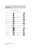
Introduction These are some of the symbols you may see on your vehicle.
Introduction Vehicle Symbol Glossary Power Windows Front/Rear Power Window Lockout Child Safety Door Lock/Unlock Interior Luggage Compartment Release Panic Alarm Engine Oil Engine Coolant Engine Coolant Temperature Do Not Open When Hot Battery Avoid Smoking, Flames, or Sparks Battery Acid Explosive Gas Fan Warning Power Steering Fluid Maintain Correct Fluid Level Service Engine Soon Engine Air Filter Passenger Compartment Air Filter Jack Check Fuel Cap Low Tire Pressure Warning MAX MIN
Instrument Cluster WARNING LIGHTS AND CHIMES Warning lights and gauges can alert you to a vehicle condition that may become serious enough to cause expensive repairs. A warning light may illuminate when a problem exists with one of your vehicle’s functions. Many lights will illuminate when you start your vehicle to make sure the bulb works. If any light remains on after starting the vehicle, refer to the respective system warning light for additional information.
Instrument Cluster Under engine misfire conditions, excessive exhaust temperatures could damage the catalytic converter, the fuel system, interior floor coverings or other vehicle components, possibly causing a fire. Electronic throttle control: Illuminates when the engine has defaulted to a “limp-home” operation. Report the fault to a dealer at the earliest opportunity. Check fuel cap: Illuminates when the fuel cap may not be properly installed.
Instrument Cluster Anti-lock brake system: If the ABS light stays illuminated or ABS continues to flash, a malfunction has been detected, have the system serviced immediately by your authorized dealer. Normal braking is still functional unless the brake warning light also is illuminated. Airbag readiness: If this light fails to illuminate when the ignition is turned to ON, continues to flash or remains on, have the system serviced immediately by your authorized dealer.
Instrument Cluster Low tire pressure warning (if equipped): Illuminates when your tire pressure is low. If the light remains ON at start up or while driving, the tire pressure should be checked. Refer to Inflating Your Tires in the Tires, Wheels and Loading chapter. When the ignition is first turned to ON, the light will illuminate for 3 seconds to ensure the bulb is working. If the light does not turn ON or begins to flash, have the system inspected by your authorized dealer.
Instrument Cluster Overdrive off: Illuminates when O/D the overdrive function of the OFF transmission has been turned off, refer to the Driving chapter. If the light does not illuminate, have the transmission serviced soon, or damage may occur. Charging system: Illuminates when the battery is not charging properly. Speed control: Illuminates when the speed control is activated. Turns off when the speed control system is deactivated.
Instrument Cluster GAUGES Speedometer: Indicates the current vehicle speed. Engine coolant temperature gauge: Indicates engine coolant temperature. At normal operating temperature, the needle will be in the normal range (between “H” and “C”). If it enters the red section, the engine is overheating. Stop the vehicle as soon as safely possible, switch off the engine and let the engine cool. Never remove the coolant reservoir cap while the engine is running or hot.
Instrument Cluster Trip odometer: Registers the miles (kilometers) of individual journeys. Press the SELECT/RESET control once to switch from the odometer to the trip odometer. Press the control again to select Trip A and Trip B features. To reset the trip, press and hold the control again until the trip reading is 0.0 miles. Tachometer: Indicates the engine speed in revolutions per minute. Driving with your tachometer pointer continuously at the top of the scale may damage the engine.
Entertainment Systems AUDIO SYSTEMS AM/FM stereo (if equipped) Driving while distracted can result in loss of vehicle control, accident and injury. Ford strongly recommends that drivers use extreme caution when using any device that may take their focus off the road. The drivers primary responsibility is the safe operation of their vehicle. Only use cell phones and other devices not essential to the driving task when it is safe to do so. / to find the 1.
Entertainment Systems 3. AM/FM: Press to choose a frequency band in radio mode. AM/FM 4. Memory preset buttons: To set 1 2 a station: Select frequency band AM/FM1/FM2; tune to a station, press and hold a preset button until sound returns. 5. Power/volume: Press to turn ON/OFF; turn to increase or decrease volume levels. 6. Tone: Press TONE until the desired level — Bass, Treble, Fade appears on the display.
Entertainment Systems Satellite Compatible AM/FM Stereo In-Dash Single CD/MP3 Radio (if equipped) Driving while distracted can result in loss of vehicle control, accident and injury. Ford strongly recommends that drivers use extreme caution when using any device that may take their focus off the road. The drivers primary responsibility is the safe operation of their vehicle. Only use cell phones and other devices not essential to the driving task when it is safe to do so. 1.
Entertainment Systems TEXT is also available when equipped with Satellite radio. Your radio comes equipped with Satellite ready capability. The kit to enable Satellite reception is available through your dealer. Detailed Satellite instructions are included with the dealer installed kit. Check with your authorized dealer for availability. 3. AUX: This function is not operational. 4. MUTE: Press to MUTE playing media; press again to return to playing media. 5. EJ: Press to eject a CD. 6.
Entertainment Systems stored in preset 1 will begin playing. If there are less than six strong stations, the system will store the last one in the remaining presets. Setting the clock: Press MENU until SELECT HOUR or SELECT ) or decrease MINUTE is displayed. Use SEL to manually increase ( ) the hours/minutes. Press MENU again to disengage clock mode. ( Folder/Track mode: In MP3 mode, press MENU until MODE appears in the display.
Entertainment Systems 18. Memory presets: To set a station: Select frequency band; tune to a station, press and hold a preset button until sound returns. 19. Power/volume: Press to turn ON/OFF; turn to increase or decrease volume levels. 20. CD: Press to enter CD mode. CD units are designed to play commercially pressed 4.75 in (12 cm) audio compact discs only. Due to technical incompatibility, certain recordable and re-recordable compact discs may not function correctly when used in Ford CD players.
Entertainment Systems For information regarding SIRIUS Satellite Radio, please call toll-free 888-539-SIRIUS (888-539-7474) or visit the SIRIUS website at www.siriusradio.com 24. CD slot: Insert a CD with the label side up. Premium Satellite Compatible AM/FM Stereo In-Dash Six CD/MP3 Radio (if equipped) Driving while distracted can result in loss of vehicle control, accident and injury. Ford strongly recommends that drivers use extreme caution when using any device that may take their focus off the road.
Entertainment Systems 2. TEXT: The filename (Fi), song title (So), artist text (Ar) or album text (AL) may be viewed while playing an MP3 selection. When MP3 selection text is shown on the message display, its corresponding text indicator (Fi, So, Ar, or AL) is shown in the elapsed time display. Press TEXT to scroll through the text fields. The display will scroll all of the text in the current field before changing to the next field.
Entertainment Systems Fade: Press FADE; then press / to shift sound to the SEL rear/front speakers. 9. Menu: Press to access the following functions: Compression: Brings soft and loud CD passages together for a more consistent listening level when in CD mode. Press MENU until compression status is displayed. Press the SEL control to enable the compression feature when COMPRESS OFF is displayed. Press the SEL control again to disable the feature when COMPRESS ON is displayed.
Entertainment Systems 14. FF(Fast forward): In CD/MP3 mode, press until desired selection is reached. 15. REW(Rewind): In CD/MP3 mode, press until desired selection is reached. 16. SAT (if equipped): Your radio comes equipped with Satellite Ready capability. The kit to enable the Satellite reception is available through your dealer. Detailed satellite instructions are included with the dealer installed kit. Check with your authorized dealer for availability. 17.
Entertainment Systems CD units are designed to play commercially pressed 4.75 in (12 cm) audio compact discs only. Due to technical incompatibility, certain recordable and re-recordable compact discs may not function correctly when used in Ford CD players. Irregular shaped CDs, CDs with a scratch protection film attached, and CDs with homemade paper (adhesive) labels should not be inserted into the CD player. The label may peel and cause the CD to become jammed.
Entertainment Systems FM: 87.7, 87.9–107.7, 107.9 MHz Radio reception factors: There are three factors that can affect radio reception: • Distance/strength: The further you travel from an FM station, the weaker the signal and the weaker the reception. • Terrain: Hills, mountains, tall buildings, power lines, electric fences, traffic lights and thunderstorms can interfere with your reception.
Climate Controls HEATER ONLY SYSTEM (IF EQUIPPED) 1. Fan speed adjustment: Controls the volume of air circulated in the vehicle. 2. Temperature selection: Controls the temperature of the airflow in the vehicle. 3. Air flow selections: Controls the direction of the airflow in the vehicle. See the following for a brief description on each control. VENT: Distributes outside air through the instrument panel vents. FLR: Distributes outside air through the floor vents.
Climate Controls MANUAL HEATING AND AIR CONDITIONING SYSTEM (IF EQUIPPED) 1. Fan speed adjustment: Controls the volume of air circulated in the vehicle. 2. Temperature selection: Controls the temperature of the airflow in the vehicle. 3. Air flow selections: Controls the direction of the airflow in the vehicle. See the following for a brief description on each control. MAX A/C: Uses recirculated air to cool the vehicle. Air flows from the instrument panel vents only.
Climate Controls To aid in side window defogging/demisting in cold weather: 1. Select MIX. 2. Set the temperature control to maintain comfort. 3. Set the fan speed to HI. Do not place objects on top of the instrument panel as these objects may become projectiles in a collision or sudden stop. REAR FAN SPEED ADJUSTMENT (IF EQUIPPED) The rear fan controls adjust the volume of air circulated in the rear of the vehicle.
Lights HEADLAMP CONTROL • The first position turns on the parking, tail, license plate and side marker lamps. • The outer position turns on the headlamps. Battery saver The battery saver can be set to turn off the courtesy lamps within 2 or 10 minutes if a door is left open and the key is not in the ignition. Demand (manually switched on) interior lamps can be set to turn off within 2 or 30 minutes after the key has been removed from the ignition.
Lights Daytime running lamps (DRL) (if equipped) Turns the headlamps on with a reduced output. To activate: • the ignition must be in the ON position and • the headlamp control is in the OFF or parking lamp position. Always remember to turn on your headlamps at dusk or during inclement weather. The Daytime Running Lamp (DRL) system does not activate the tail lamps and generally may not provide adequate lighting during these conditions.
Lights PANEL DIMMER CONTROL To adjust the brightness of the instrument panel, rotate the dimmer control clockwise/counterclockwise when the headlamp control is in the parking lamp or low-beam position. To turn on the interior lamps, rotate the dimmer control fully counterclockwise past the detent. The dome lamp will not illuminate if the control switch is not rotated past the detent.
Lights 3. Turn on the low beam headlamps and open the hood. 4. Locate the high intensity area of the beam pattern and place the top edge of the intensity zone even with the horizontal reference line (4). If the top edge of the high intensity area is not even with the horizontal line, follow the next step to adjust it. 5. Locate the vertical adjuster (1) for each headlamp. Adjust the aim by turning the adjuster control either clockwise (to adjust up) or counterclockwise (to adjust down). 6.
Lights • (1) 8 feet (2.4 meters) • (2) Center height of lamp to ground • (3) 25 feet (7.6 meters) • (4) Horizontal reference line 2. Measure the height from the center of your headlamp (indicated by a 3.0 mm circle on the lens) to the ground and mark an 8 foot (2.4 meter) horizontal reference line on the vertical wall or screen at this height (a piece of masking tape works well). 3. Turn on the low beam headlamps to illuminate the wall or screen and open the hood.
Lights TURN SIGNAL CONTROL • Push down to activate the left turn signal. • Push up to activate the right turn signal.
Lights Front and rear courtesy/reading lamps The dome portion of the lamp, the center light, can be turned on when the headlamp control is rotated fully counterclockwise or when any door is opened. The reading lamp portion, the two outer lights, can only be toggled on and off at the lamp. BULB REPLACEMENT Headlamp Condensation The headlamps are vented to equalize pressure. When moist air enters the headlamp(s) through the vents, there is a possibility that condensation can occur.
Lights Function Number of bulbs 2 Trade number Side marker with 194 sealed beam Back-up lamps 2 3156K or 3156 License plate lamp 1 168 Stop/tail/turn/side 2 3457K or 3357K marker lamp High-mount brakelamp 2 912 Cargo lamp 1 211-2 Dome lamp (standard) 1 912 Map/reading lamp 2 211-2 All replacement bulbs are clear in color except where noted. To replace all instrument panel lights - see your authorized dealer Replacing exterior bulbs Check the operation of all the bulbs frequently.
Lights 4. Remove the bulb assembly by turning it counterclockwise and pulling it straight out. Handle a halogen headlamp bulb carefully and keep out of children’s reach. Grasp the bulb only by its plastic base and do not touch the glass. The oil from your hand could cause the bulb to break the next time the headlamps are operated. Note: If the bulb is accidentally touched, it should be cleaned with alcohol before being used. To install the new bulb, follow the removal procedures in reverse order.
Lights Aerodynamic Sealed beam 3. Rotate the bulb socket counterclockwise and remove. 4. Carefully pull the bulb straight out of the socket. To complete installation, follow the removal procedures in reverse order. Replacing side marker bulbs 1. Make sure the headlamp control is in the OFF position. 2. Remove headlamp assembly, refer to Replacing headlamp bulbs in this section.
Lights Sealed beam 3. Rotate the bulb socket counterclockwise and remove. 4. Carefully pull the bulb straight out of the socket. To complete installation, follow the removal procedures in reverse order. Replacing high-mount brakelamp bulbs The interior cargo lamp (if equipped), on vehicles without a rear headliner, will have to be removed from under the high-mount brakelamp assembly located inside the vehicle. Then: 1.
Lights Replacing license plate lamp bulbs 1. Turn the headlamp switch to OFF and then remove the two screws and the license plate lamp assembly from the rear door. 2. Remove bulb socket from lamp assembly by turning counterclockwise. 3. Pull the bulb out from socket and push in the new bulb. To install the new bulb, follow the removal procedures in reverse order. Replacing stop/turn/tail/side marker/backup lamp bulbs The stop/turn/tail/side marker/backup lamp bulbs are located in the tail lamp assembly.
Driver Controls MULTI-FUNCTION LEVER Windshield wiper: Rotate the end of the control away from you to increase the speed of the wipers; rotate towards you to decrease the speed of the wipers. Windshield washer: Push the end of the stalk: • briefly: causes a single swipe of the wipers without washer fluid. • a quick push and hold: the wipers will swipe three times with washer fluid. • a long push and hold: the wipers and washer fluid will be activated for up to ten seconds.
Driver Controls TILT STEERING WHEEL To adjust the steering wheel: 1. Pull and hold the steering wheel release control toward you. 2. Move the steering wheel up or down until you find the desired location. 3. Release the steering wheel release control. This will lock the steering wheel in position. Never adjust the steering wheel when the vehicle is moving. ILLUMINATED VISOR MIRROR (IF EQUIPPED) Lift the mirror cover to turn on the visor mirror lamps.
Driver Controls Storage compartment (if equipped) Press the release on the door to open the storage compartment. The storage compartment may be used to secure sunglasses or a similar object. Installing a garage door opener (if equipped) The storage compartment can be converted to accommodate a variety of aftermarket garage door openers: 1. Place VELCRO威 hook onto side of aftermarket transmitter opposite of actuator control. 2. Place the transmitter into storage compartment, control down. 3.
Driver Controls Electronic compass/temperature display (if equipped) Outside air temperature The outside temperature display is contained in the overhead console. The temperature display can be turned off and on by pressing the SELECT control on the overhead console. The temperature can be displayed in Centigrade or Fahrenheit by pressing the SELECT 73˚ NW control.
Driver Controls 3. Press and hold the SELECT control until VAR appears in the display, then release. The display should show the current zone number. 9 4. Press the SELECT control until the desired zone number appears. The display will flash and then return to normal operation. The zone is now updated.
Driver Controls To prevent the fuse from being blown, do not use the power point(s) over the vehicle capacity of 12 VDC/180W. If the power point or cigar lighter socket is not working, a fuse may have blown. Refer to Fuses and relays in the Roadside Emergencies chapter for information on checking and replacing fuses. To have full capacity usage of your power point, the engine is required to be running (in a safe manner) to avoid unintentional discharge of the battery.
Driver Controls Press and hold the bottom part of the rocker switch to open the window. Press and hold the top part of the rocker switch to close the window. Accessory delay With accessory delay, the window switches and radio may be used for up to ten minutes after the ignition switch is turned to the OFF position, or until any door is opened. INTERIOR MIRROR The interior rear view mirror has two pivot points on the support arm which lets you adjust the mirror UP or DOWN and from SIDE to SIDE.
Driver Controls Spotter mirror on standard mirror (if equipped) The spotter mirror only can be tilted from top to bottom. Move the lower mirror manually up/down to increase side and rear visibility. Apply pressure only in the center of the spotter mirror along the top or bottom edges to adjust the tilt feature. Do not apply any force on the left or right edges of the standard mirror spotter section, as this may lead to a mirror fracture.
Driver Controls The telescoping feature (if equipped) allows the mirror to extend approximately 3.15 inches (80 mm). This feature is especially useful to the driver when towing a trailer. SPEED CONTROL (IF EQUIPPED) With speed control set, you can maintain a set speed without keeping your foot on the accelerator pedal. Do not use the speed control in heavy traffic or on roads that are winding, slippery or unpaved.
Driver Controls Resuming a set speed Press the RES (resume) control and release it. This will automatically return the vehicle to the previously set speed. RES SET ACCEL COAST Increasing speed while using speed control There are two ways to set a higher speed: • Press and hold the SET ACCEL control until you get to the desired speed, then release the control. You can also use the SET ACCEL control to operate the Tap-Up function.
Driver Controls • Depress the brake pedal until the desired vehicle speed is reached, press the SET ACCEL control. RES SET ACCEL COAST Turning off speed control There are two ways to turn off the speed control: • Depress the brake pedal. This will not erase your vehicle’s previously set speed. • Press the speed control OFF control. Note: When you turn off the speed control or the ignition, your speed control set speed memory is erased.
Locks and Security KEYS The key operates all locks on your vehicle. You should always carry a second key with you in a safe place in case you require it in an emergency. If your vehicle is equipped with the SecuriLock™ Passive Anti-theft system, your keys are electronically coded to your vehicle; using a non-coded key will not permit your vehicle to start. If you lose your dealer supplied keys, replacement keys are available through your authorized dealer.
Locks and Security Deactivating/activating autolock feature Your vehicle comes with the autolock feature disabled; there are two methods to enable/disable this feature: • Through your authorized dealer, or • by using a power door unlock/lock procedure. Power door lock switch autolock enable/disable procedure Before starting, ensure the ignition is in the 3 (OFF) position and all vehicle doors are closed. You must complete Steps 1–5 within 30 seconds or the procedure will have to be repeated.
Locks and Security Back cargo door lock (if equipped) The passenger side rear cargo door has a power door lock control mounted on the inside of the door. When this lock is pressed, all doors will lock/unlock. E-Guard Cargo Protection System™ (if equipped) The E-Guard Cargo Protection System™ insures that the cargo doors are double locked for extra security. E-Guard Cargo Protection System™ features • The E-Guard Cargo Protection System™ is available with either power or manual door locks.
Locks and Security For vehicles equipped with manual door locks: • The front door locks can be locked by using either the key or the manual door lock. • In order to activate the E-Guard Cargo Protection System™, use the key or the manual door lock to lock the side and back cargo doors. • The cargo doors cannot be unlocked using the manual door lock. If equipped with E-Guard Cargo Protection System™ occupants may become trapped in the cargo area unless the exit procedure is followed.
Locks and Security • The rear door handle is located in the rear door below the glass. To open the side or back cargo doors from the inside: 1. Unlock the E-Guard Cargo Protection System™ using the emergency handle. 2. Unlatch the door using the inside release handle. REMOTE ENTRY SYSTEM (IF EQUIPPED) This device complies with part 15 of the FCC rules and with RSS-210 of Industry Canada.
Locks and Security The remote entry system allows you to lock or unlock all vehicle doors without a key. Note: • The lock and unlock features work when the ignition is in any position. • The panic feature is active when the ignition is in either the 1 (ACCESSORY), 2 (LOCK) or 3 (OFF) positions. If there are problems with the remote entry system, make sure to take ALL remote entry transmitters with you to the authorized dealer in order to aid in troubleshooting the problem. Two step door unlocking 1.
Locks and Security flash twice to indicate that the vehicle has switched to one step unlocking. Repeat the procedure to switch back to two-step unlocking. Locking the doors 1. Press and release to lock all the doors. and release again within three seconds to confirm that all 2. Press the doors are closed and locked. Note: The doors will lock again, and the horn will chirp once. Car finder twice within three seconds. The horn will chirp and the turn Press lamps will flash.
Locks and Security 2. Do not wipe off any grease on the battery terminals on the back surface of the circuit board. 3. Remove the old battery. Note: Please refer to local regulations when disposing of transmitter batteries. 4. Insert the new battery. Refer to the diagram inside the remote entry transmitter for the correct orientation of the battery. Press the battery down to ensure that the battery is fully seated in the battery housing cavity. 5. Snap the two halves back together.
Locks and Security Note: Ensure the brake pedal is not 4 depressed during this sequence. 3 To reprogram the remote entry 5 transmitters: 2 1. Ensure the vehicle is electronically unlocked. 2. Place the key in the ignition and 1 turn from the (2) LOCK position to (3) OFF. 3. Cycle eight times rapidly (within 10 seconds) between the (3) OFF position and (4) ON. Note: The eighth turn must end in the (4) ON position. 4. The doors will lock, then unlock, to confirm that the programming mode has been activated.
Locks and Security The inside lights will not turn off if: • they have been turned on with the dimmer control, or • any door is open. SECURILOCK™ PASSIVE ANTI-THEFT SYSTEM (IF EQUIPPED) SecuriLock™ passive anti-theft system is an engine immobilization system. This system is designed to help prevent the engine from being started unless a coded key programmed to your vehicle is used. The use of the wrong type of coded key may lead to a “no-start” condition.
Locks and Security • When the igniton is in the 4 (ON) position, the indicator will glow for 3 seconds to indicate the engine is enabled. Automatic arming The vehicle is armed immediately after switching the ignition to the 2 (LOCK) position. 3 4 5 2 1 Automatic disarming Switching the ignition to the 4 (ON) position with a coded key disarms the vehicle.
Locks and Security 1. Insert the first previously 4 programmed coded key into the 3 ignition and turn the ignition from 5 the 3 (OFF) position to the 4 (ON) position (maintain ignition in the 4 2 (ON) position for at least one second, but no more than ten seconds). 1 2. Turn ignition from the 4 (ON) position back to the 3 (OFF) position in order to remove the first coded key from the ignition. 3.
Seating and Safety Restraints SEATING Notes: Reclining the seatback can cause an occupant to slide under the seat’s safety belt, resulting in severe personal injuries in the event of a collision. Do not pile cargo higher than the seatbacks to reduce the risk of injury in a collision or sudden stop. Before returning the seatback to its original position, make sure that cargo or any objects are not trapped behind the seatback.
Seating and Safety Restraints Pull lever up to adjust seatback. Before returning the seatback to its original position, make sure that cargo or any objects are not trapped behind the seatback. After returning the seatback to its original position, pull on the seatback to ensure that it has fully latched. An unlatched seat may become dangerous in the event of a sudden stop or collision.
Seating and Safety Restraints Press to raise or lower the rear portion of the seat cushion. Press the control to move the seat forward, backward, up or down. REAR SEATS Rear captains chair adjust — passenger side only Pull the lever forward to adjust the seat forward or backward.
Seating and Safety Restraints Quick release captains chair (7 passenger configuration second row only) To remove the seat: 1. Disengage the lap/shoulder belt from the seat by inserting a key or small screwdriver into the slot in the detachable anchor and lifting upward. 2. Pull the seat latch handle, then pull the seat toward the right side of the vehicle to disengage four pins from the floor mount. 3. Remove the seat.
Seating and Safety Restraints 1. Position the seat to the floor mount. 2. Pull the seat latch handle downward to lock the seat in position. 3. Make sure the safety belt is not twisted, then insert the safety belt tongue into detachable anchor until you hear a “click” and feel the latch engage. Rear bench seat To remove the seats: 1. Disengage the lap/shoulder belt from the seat by inserting a key or small screwdriver into the slot in the detachable anchor and lifting upward (2nd row passenger side only).
Seating and Safety Restraints 2. Find the clips attached near the ends of the lap/shoulder belts. 3. Clip the end of the belt to the stationary portion of the shoulder belt coming out of the trim panel. The end of the shoulder belt must be clipped in order to keep it from striking anything during vehicle operation.
Seating and Safety Restraints 4. With assistance, pull the LH/RH seat latch release straps (1) (located behind the latch mechanisms) to release the latch from the rear strikers. 5. Lift the rear end of seat upward and rearward by pushing on the seatback (2) and lifting the seat cushion (3) to disengage the front seat hook and the rear seat latch from the striker. 6. With assistance, remove the seat assembly. • To remove the 3rd, 4th, and 5th row seats (if equipped), repeat Steps 1 through 6.
Seating and Safety Restraints 5. After the front LH/RH hooks are engaged to the LH/RH front striker pins, pull LH/RH seat latch release straps to allow engagement of the latch to the striker pins. Refer to the illustration in To remove the rear seats above. 6. Pull/push seat back forward/backward to check for proper seat installation. Always latch the vehicle seat to the floor, whether the seat is occupied or empty. If not latched, the seat may cause injury during a sudden stop.
Seating and Safety Restraints In a rollover crash, an unbelted person is significantly more likely to die than a person wearing a safety belt. Each seating position in your vehicle has a specific safety belt assembly which is made up of one buckle and one tongue that are designed to be used as a pair. 1) Use the shoulder belt on the outside shoulder only. Never wear the shoulder belt under the arm. 2) Never swing the safety belt around your neck over the inside shoulder.
Seating and Safety Restraints • Front and rear seats All safety restraints in the vehicle are combination lap and shoulder belts. All of the passenger combination lap and shoulder belts have two types of locking modes described below: Vehicle sensitive mode This is the normal retractor mode, which allows free shoulder belt length adjustment to your movements and locking in response to vehicle movement.
Seating and Safety Restraints How to use the automatic locking mode • Buckle the combination lap and shoulder belt. • Grasp the shoulder portion and pull downward until the entire belt is pulled out. • Allow the belt to retract. As the belt retracts, you will hear a clicking sound. This indicates the safety belt is now in the automatic locking mode.
Seating and Safety Restraints BELT AND RETRACTOR ASSEMBLY MUST BE REPLACED if the safety belt assembly “automatic locking retractor” feature or any other safety belt function is not operating properly when checked by an authorized dealer. Failure to replace the Belt and Retractor assembly could increase the risk of injury in collisions. Safety belt pretensioner Your vehicle is equipped with safety belt pretensioners at the driver and front outboard passenger seating positions.
Seating and Safety Restraints Safety belt warning light and indicator chime The safety belt warning light illuminates in the instrument cluster and a chime sounds to remind the occupants to fasten their safety belts. Conditions of operation If... The driver’s safety belt is not buckled before the ignition switch is turned to the ON position... The driver’s safety belt is buckled while the indicator light is illuminated and the warning chime is sounding...
Seating and Safety Restraints If... The driver’s safety belt is not buckled approximately 5 seconds after the safety belt warning light has turned off... The driver’s safety belt is buckled while the safety belt indicator light is illuminated and the safety belt warning chime is sounding... The driver’s safety belt is buckled before the ignition switch is turned to the ON position... Then...
Seating and Safety Restraints Reasons given... “I was in a hurry” “Safety belts don’t work” “Traffic is light” “Belts wrinkle my clothes” “The people I’m with don’t wear belts” “I have an airbag” “I’d rather be thrown clear” Consider... Prime time for an accident. Belt-Minder威 reminds us to take a few seconds to buckle up. Safety belts, when used properly, reduce risk of death to front seat occupants by 45% in cars, and by 60% in light trucks.
Seating and Safety Restraints Deactivating/activating the Belt-Minder姞 feature Read Steps 1 - 5 thoroughly before proceeding with the deactivation/activation programming procedure.
Seating and Safety Restraints • This will enable the Belt-Minder威 feature for that seating position if it is currently disabled. As confirmation, the safety belt warning light will flash four times per second for three seconds, followed by three seconds with the light off, then followed by the safety belt warning light flashing four times per second for three seconds again. 5. After receiving confirmation, the deactivation/activation procedure is complete.
Seating and Safety Restraints Failure to inspect and if necessary replace the safety belt assembly under the above conditions could result in severe personal injuries in the event of a collision. For proper care of soiled safety belts, refer to Interior in the Cleaning chapter. AIRBAG SUPPLEMENTAL RESTRAINT SYSTEM (SRS) Important SRS precautions The SRS is designed to work with the safety belt to help protect the driver and right front passenger from certain upper body injuries.
Seating and Safety Restraints Always transport children 12 years old and under in the back seat and always properly use appropriate child restraints. Never place a rear-facing child seat in front of an active airbag. If you must transport a forward-facing child in the front seat, move the seat all the way back and use appropriate restraints.
Seating and Safety Restraints Children and airbags Children must always be properly restrained. Accident statistics suggest that children are safer when properly restrained in the rear seating positions than in the front seating position. Failure to follow these instructions may increase the risk of injury in a collision. Airbags can kill or injure a child in a child seat. NEVER place a rear-facing child seat in front of an active airbag.
Seating and Safety Restraints The airbags inflate and deflate rapidly upon activation. After airbag deployment, it is normal to notice a smoke-like, powdery residue or smell the burnt propellant. This may consist of cornstarch, talcum powder or sodium compounds which may irritate the skin and eyes, but none of the residue is toxic. While the SRS is designed to help reduce serious injuries, contact with a deploying airbag may also cause abrasions, swelling or temporary hearing loss.
Seating and Safety Restraints Determining if the system is operational The SRS uses a readiness light in the instrument cluster or a tone to indicate the condition of the system. Refer to Airbag readiness section in the Instrument Cluster chapter. Routine maintenance of the airbag is not required. A difficulty with the system is indicated by one or more of the following: • The readiness light will either flash or stay lit. • The readiness light will not illuminate immediately after ignition is turned on.
Seating and Safety Restraints Passenger airbag ON/OFF switch (if equipped) Note: The passenger airbag ON/OFF switch (if equipped) may be on vehicles with no rear seats and a gross vehicle weight rating (GVWR) greater than 8500. See Vehicle loading – with and without a trailer in the Tires, Wheels and loading chapter. An airbag ON/OFF switch (if equipped) may have been installed in this vehicle.
Seating and Safety Restraints In order to avoid inadvertent activation of the switch, always remove the ignition key from the passenger air bag ON/OFF switch. An infant in a rear-facing seat faces a high risk of serious or fatal injuries from a deploying passenger airbag. Rear facing infant seats should NEVER be placed in the front seats, unless the passenger airbag is turned off. Turning the passenger airbag back on The passenger airbag remains OFF until you turn it back ON. 1.
Seating and Safety Restraints If your vehicle has rear seats, always transport children who are 12 and younger in the rear seat. Always use safety belts and child restraints properly. DO NOT place a child in a rear facing infant seat in the front seat unless your vehicle is equipped with an airbag ON/OFF switch and the passenger airbag is turned OFF.
Seating and Safety Restraints • the child has a medical condition which, according to the child’s physician, makes it necessary for the child to ride in the front seat so that the driver can constantly monitor the child’s condition. 3. Medical condition.
Seating and Safety Restraints • the child has a medical condition that, according to the child’s physician, makes it necessary for the child to ride in the front seat so that the driver can monitor the child’s condition. 3.
Seating and Safety Restraints Never let a passenger hold a child on his or her lap while the vehicle is moving. The passenger cannot protect the child from injury in a collision. Always follow the instructions and warnings that come with any infant or child restraint you might use. Ford recommends using child safety seats equipped with LATCH attachments, attached to LATCH anchors and tether anchors.
Seating and Safety Restraints Do not leave children, unreliable adults, or pets unattended in your vehicle. Child booster seats Children outgrow a typical convertible or toddler seat when they weigh 40 lb. (18 kg) and are around 4 years of age. Although the lap/shoulder belt will provide some protection, these children are still too small for lap/shoulder belts to fit properly, which could increase the risk of serious injury in a crash.
Seating and Safety Restraints Types of booster seats There are two types of belt-positioning booster seats: • Those that are backless. If your backless booster seat has a removable shield, remove the shield and use the lap/shoulder belt. If a seating position has a low seat back and no head restraint, a backless booster seat may place your child’s head (top of ear level) above the top of the seat.
Seating and Safety Restraints Children and booster seats vary widely in size and shape. Choose a booster that keeps the lap belt low and snug across the hips, never up across the stomach, and lets you adjust the shoulder belt to cross the chest and rest snugly near the center of the shoulder. The drawings below compare the ideal fit (center) to a shoulder belt uncomfortably close to the neck and a shoulder belt that could slip off the shoulder.
Seating and Safety Restraints Never use pillows, books, or towels to boost a child. They can slide around and increase the likelihood of injury or death in a collision. SAFETY SEATS FOR CHILDREN Child and infant or child safety seats Use a safety seat that is recommended for the size and weight of the child. Carefully follow all of the manufacturer’s instructions with the safety seat you put in your vehicle.
Seating and Safety Restraints Ford recommends the use of a child safety seat having a top tether strap. Install the child safety seat in a seating position with LATCH and tether anchors. For more information on top tether straps and anchors, refer to Attaching safety seats with tether straps in this chapter. For more information of LATCH anchors refer to Attaching safety seats with LATCH (Lower Anchors and Tethers for Children) attachments in this chapter.
Seating and Safety Restraints 2. Pull down on the shoulder belt and then grasp the shoulder belt and lap belt together. 3. While holding the shoulder and lap belt portions together, route the tongue through the child seat according to the child seat manufacturer’s instructions. Be sure the belt webbing is not twisted. 4. Insert the belt tongue into the proper buckle (the buckle closest to the direction the tongue is coming from) for that seating position until you hear a snap and feel the latch engage.
Seating and Safety Restraints 5. To put the retractor in the automatic locking mode, grasp the shoulder portion of the belt and pull downward until all of the belt is extracted. 6. Allow the belt to retract. The belt will click as it retracts to indicate it is in the automatic locking mode. 7. Pull the lap belt portion across the child seat toward the buckle and pull up on the shoulder belt while pushing down with your knee on the child seat. 8.
Seating and Safety Restraints Attaching safety seats with tether straps Children should be placed in the rear in an appropriate child safety seat that is properly secured to the vehicle. When using forward-facing child safety seats in vehicles with only two seating positions so the forward-facing child safety seat cannot be placed in the rear of the vehicle, move the passenger seat as far back from the instrument panel as possible.
Seating and Safety Restraints 1. Position the child safety seat on the front right-hand passenger seat. 2. Adjust the front right-hand passenger seat full forward. 3. Route the child safety seat tether strap over the back of the front right-hand passenger seat as shown. 4. Clip the tether strap hook to the seat pedestal to the location shown.
Seating and Safety Restraints 5. Adjust the front right hand passenger seat to the full rearward position. 6. Install the child safety seat tightly using the LATCH anchors or safety belts. Follow the instructions in this chapter. 7. Tighten the child safety seat tether strap according to the manufacturer’s instructions. Second row bucket seats (Quads) The tether strap can be attached directly to the tether bracket under the back edge of the seat cushion.
Seating and Safety Restraints 1. Position the child safety seat on the second row left hand or right hand bucket seat. 2. Route the child safety tether strap over the back of the left hand or right hand second row bucket seat. 3. Clip the tether strap hook to the seat pedestal at the location shown. 4. Install the child safety seat tightly using the LATCH anchors or safety belts. Follow the instructions in this chapter. 5.
Seating and Safety Restraints 2. Route the child safety tether strap over the back of the bench seat. 3. Clip the center tether strap hook to the tether bracket mounted under rear rail of seat cushion frame. Clip the outboard tether strap hooks to the tether bracket slot provided on the left side of each seat pedestal. The slot is located between the two holes. 4. Install the child safety seat tightly using the LATCH anchors or safety belts. Follow the instructions in this chapter. 5.
Seating and Safety Restraints • Five passenger crew van • Seven passenger wagon • Eight passenger wagon • Twelve passenger wagon 109 2008 Econoline (eco) Owners Guide (post-2002-fmt) USA (fus)
Seating and Safety Restraints • Fifteen passenger wagon represents LATCH anchors. represents tether strap anchors. Never attach two LATCH child safety seats to the same anchor. In a crash, one anchor may not be strong enough to hold two child safety seat attachments and may break, causing serious injury or death. The lower anchors for child seat installation are located at the rear section of the seat between the cushion and seat back.
Seating and Safety Restraints Each time you use the safety seat, check that the seat is properly attached to the lower anchors and tether anchor. Try to tilt the child seat from side to side. Also try to tug the seat forward. Check to see if the anchors hold the seat in place. If the safety seat is not anchored properly, the risk of a child being injured in a crash greatly increases.
Tires, Wheels and Loading NOTICE TO UTILITY VEHICLE AND TRUCK OWNERS Utility vehicles and trucks handle differently than passenger cars in the various driving conditions that are encountered on streets, highways and off-road. Utility vehicles and trucks are not designed for cornering at speeds as high as passenger cars any more than low-slung sports cars are designed to perform satisfactorily under off-road conditions. Utility vehicles have a significantly higher rollover rate than other types of vehicles.
Tires, Wheels and Loading VEHICLE CHARACTERISTICS How your vehicle differs from other vehicles SUV and trucks can differ from some other vehicles in a few noticeable ways. Your vehicle may be: • Higher – to allow higher load carrying capacity and to allow it to travel over rough terrain without getting hung up or damaging underbody components. • Shorter – to give it the capability to approach inclines and drive over the crest of a hill without getting hung up or damaging underbody components.
Tires, Wheels and Loading INFORMATION ABOUT UNIFORM TIRE QUALITY GRADING Tire Quality Grades apply to new pneumatic passenger car tires. The Quality grades can be found where applicable on the tire sidewall between tread shoulder and maximum section width. For example: • Treadwear 200 Traction AA Temperature A These Tire Quality Grades are determined by standards that the United States Department of Transportation has set. Tire Quality Grades apply to new pneumatic passenger car tires.
Tires, Wheels and Loading The traction grade assigned to this tire is based on straight-ahead braking traction tests, and does not include acceleration, cornering, hydroplaning or peak traction characteristics. Temperature A B C The temperature grades are A (the highest), B and C, representing the tire’s resistance to the generation of heat and its ability to dissipate heat when tested under controlled conditions on a specified indoor laboratory test wheel.
Tires, Wheels and Loading • PSI: Pounds per square inch, a standard unit of air pressure. • Cold inflation pressure: The tire pressure when the vehicle has been stationary and out of direct sunlight for an hour or more and prior to the vehicle being driven for 1 mile (1.6 km). • Recommended inflation pressure: The cold inflation pressure found on the Safety Compliance Certification Label or Tire Label located on the B-Pillar or the edge of the driver’s door.
Tires, Wheels and Loading Under-inflation is the most common cause of tire failures and may result in severe tire cracking, tread separation or ⬙blowout⬙, with unexpected loss of vehicle control and increased risk of injury. Under-inflation increases sidewall flexing and rolling resistance, resulting in heat buildup and internal damage to the tire. It also may result in unnecessary tire stress, irregular wear, loss of vehicle control and accidents.
Tires, Wheels and Loading Note: If you have to drive a distance to get air for your tire(s), check and record the tire pressure first and add the appropriate air pressure when you get to the pump. It is normal for tires to heat up and the air pressure inside to go up as you drive. 2. Remove the cap from the valve on one tire, then firmly press the tire gauge onto the valve and measure the pressure with the tire gauge. 3. Add enough air to reach the recommended air pressure.
Tires, Wheels and Loading Tire inflation information All tires with Steel Carcass Plies (if equipped): This type of tire utilizes steel cords in the sidewalls. As such, they cannot be treated like normal light truck tires. Tire service, including adjusting tire pressure, must be performed by personnel trained, supervised and equipped according to Federal Occupational Safety and Health Administration (OSHA) regulations.
Tires, Wheels and Loading Stay out of the trajectory (1) as indicated in the illustration. TIRE CARE Inspecting your tires Periodically inspect the tire treads for uneven or excessive wear and remove objects such as stones, nails or glass that may be wedged in the tread grooves. Check for holes or cuts that may permit air leakage from the tire and make necessary repairs. Also inspect the tire sidewalls for cracking, cuts, bruises and other signs of damage or excessive wear.
Tires, Wheels and Loading Improper or inadequate vehicle maintenance can cause tires to wear abnormally. Inspect all your tires, including the spare, frequently, and replace them if one or more of the following conditions exist: Tire wear When the tread is worn down to 1/16th of an inch (2 mm), tires must be replaced to help prevent your vehicle from skidding and hydroplaning.
Tires, Wheels and Loading U.S. DOT Tire Identification Number (TIN) Both U.S. and Canada Federal regulations require tire manufacturers to place standardized information on the sidewall of all tires. This information identifies and describes the fundamental characteristics of the tire and also provides a U.S. DOT Tire Identification Number for safety standard certification and in case of a recall. This begins with the letters “DOT” and indicates that the tire meets all federal standards.
Tires, Wheels and Loading When mounting replacement tires and wheels, you should not exceed the maximum pressure indicated on the sidewall of the tire to set the beads without additional precautions listed below. If the beads do not seat at the maximum pressure indicated, re-lubricate and try again. When inflating the tire for mounting pressures up to 20 psi greater than the maximum pressure on the tire sidewall, the following precautions must be taken to protect the person mounting the tire: 1.
Tires, Wheels and Loading • Do not run over curbs or hit the tire against a curb when parking If your vehicle is stuck in snow, mud, sand, etc., do not rapidly spin the tires; spinning the tires can tear the tire and cause an explosion. A tire can explode in as little as three to five seconds. Do not spin the wheels at over 35 mph (56 km/h). The tires may fail and injure a passenger or bystander.
Tires, Wheels and Loading • Rear Wheel Drive (RWD) vehicles/Four Wheel Drive (4WD)/ All Wheel Drive (AWD) vehicles (front tires at top of diagram) Sometimes irregular tire wear can be corrected by rotating the tires. Note: If your tires show uneven wear ask an authorized dealer to check for and correct any wheel misalignment, tire imbalance or mechanical problem involved before tire rotation. Note: Your vehicle may be equipped with a dissimilar spare tire/wheel.
Tires, Wheels and Loading • DRW – Six tire rotation If your vehicle is equipped with dual rear wheels it is recommended that the front and rear tires (in pairs) be rotated only side to side. We do not recommend splitting up the dual rear wheels. Rotate them side to side as a set/pair. After tire rotation, inflation pressures must be adjusted for the tires new positions in accordance with vehicle requirements. Sometimes irregular tire wear can be corrected by rotating the tires.
Tires, Wheels and Loading Information on “P” type tires P215/65R15 95H is an example of a tire size, load index and speed rating. The definitions of these items are listed below. (Note that the tire size, load index and speed rating for your vehicle may be different from this example.) 1. P: Indicates a tire, designated by the Tire and Rim Association (T&RA), that may be used for service on cars, SUVs, minivans and light trucks.
Tires, Wheels and Loading Note: You may not find this information on all tires because it is not required by federal law. Letter rating Speed rating - mph (km/h) M 81 mph (130 km/h) N 87 mph (140 km/h) Q 99 mph (159 km/h) R 106 mph (171 km/h) S 112 mph (180 km/h) T 118 mph (190 km/h) U 124 mph (200 km/h) H 130 mph (210 km/h) V 149 mph (240 km/h) W 168 mph (270 km/h) Y 186 mph (299 km/h) Note: For tires with a maximum speed capability over 149 mph (240 km/h), tire manufacturers sometimes use the letters ZR.
Tires, Wheels and Loading 12. Treadwear, Traction and Temperature Grades • Treadwear: The treadwear grade is a comparative rating based on the wear rate of the tire when tested under controlled conditions on a specified government test course. For example, a tire graded 150 would wear one and one-half (11⁄2) times as well on the government course as a tire graded 100. • Traction: The traction grades, from highest to lowest are AA, A, B, and C.
Tires, Wheels and Loading Additional information contained on the tire sidewall for “LT” type tires “LT” type tires have some additional information beyond those of “P” type tires; these differences are described below: 1. LT: Indicates a tire, designated by the Tire and Rim Association (T&RA), that is intended for service on light trucks. 2. Load Range/Load Inflation Limits: Indicates the tire’s load-carrying capabilities and its inflation limits. 3. Maximum Load Dual lb.
Tires, Wheels and Loading Information on “T” type tires “T” type tires have some additional information beyond those of “P” type tires; these differences are described below: T145/80D16 is an example of a tire size. Note: The temporary tire size for your vehicle may be different from this example. 1. T: Indicates a type of tire, designated by the Tire and Rim Association (T&RA), that is intended for temporary service on cars, SUVs, minivans and light trucks. 2.
Tires, Wheels and Loading TIRE PRESSURE MONITORING SYSTEM (TPMS) (IF EQUIPPED) Each tire, including the spare (if provided), should be checked monthly when cold and inflated to the inflation pressure recommended by the vehicle manufacturer on the vehicle placard or tire inflation pressure label. (If your vehicle has tires of a different size than the size indicated on the vehicle placard or tire inflation pressure label, you should determine the proper tire inflation pressure for those tires.
Tires, Wheels and Loading The Tire Pressure Monitoring System complies with part 15 of the FCC rules and with RSS-210 of Industry Canada. Operation is subject to the following two conditions: (1) This device may not cause harmful interference, and (2) This device must accept any interference received, including interference that may cause undesired operation. The Tire Pressure Monitoring System is NOT a substitute for manually checking tire pressure.
Tires, Wheels and Loading Understanding your Tire Pressure Monitoring System (TPMS) The Tire Pressure Monitoring System measures pressure in your four road tires and sends the tire pressure readings to your vehicle. The Low Tire Warning Lamp will turn ON if the tire pressure is significantly low. Once the light is illuminated, your tires are under inflated and need to be inflated to the manufacturer’s recommended tire pressure.
Tires, Wheels and Loading Low Tire Possible Pressure Warning cause Light Solid Warning Light Tire(s) under-inflated Spare tire in use TPMS malfunction Tire rotation without sensor training Customer Action Required 1. Check your tire pressure to ensure tires are properly inflated; refer to Inflating your tires in this chapter. 2.
Tires, Wheels and Loading Low Tire Pressure Warning Light Flashing Warning Light Possible cause Customer Action Required Spare tire in use Your temporary spare tire is in use. Repair the damaged road wheel and re-mount it on the vehicle to restore system functionality. For a description of how the system functions under these conditions, refer to When your temporary spare tire is installed in this section.
Tires, Wheels and Loading tires are flat, repair as necessary. Check air pressure in the road tires. If any tire is under-inflated, carefully drive the vehicle to the nearest location where air can be added to the tires. Inflate all the tires to the recommended inflation pressure. TPMS reset procedure (if applicable) This procedure is only required after tire rotation on vehicles with different front and rear tire pressures.
Tires, Wheels and Loading TPMS reset tool A special TPMS reset tool has been provided with your vehicle to reset your TPMS after tire rotation. The tool is located with your Owner’s Guide materials. Please take the tool with the provided Velcro威 strip on the back and mount it in the bottom right corner of your Owner’s Guide case (as shown) for safe keeping.
Tires, Wheels and Loading 3. Press and hold the brake pedal for two (2) seconds, then release. 4. Turn the ignition to OFF/LOCK (DO NOT remove the key.) 5. Cycle the ignition from OFF/LOCK to RUN three (3) times ending in RUN. DO NOT start the engine. If reset mode has been entered successfully, the horn will sound once, the TPMS indicator will flash and the message center will display TRAIN LF TIRE.
Tires, Wheels and Loading 1. Left front tire: Place the TPMS reset tool against the left front tire where the tire meets the rim, opposite from the valve stem (1) as shown. This is where the sensor is located inside the rim. The tool needs to be held against the tire sidewall opposite the valve stem as illustrated with the arrow on the tool pointing towards the rim; do not use the tool with the arrow pointing away from the rim as it may not activate the sensor. 2.
Tires, Wheels and Loading Rotation, pressure adjustment and TPMS reset example The following example describes all the major steps involved in rotating tires on a vehicle with different front and rear tire pressures. It illustrates that the TPMS reset procedure needs to follow tire rotation and pressure adjustment to avoid a possible false low tire warning. Example: A particular vehicle has the following recommended tire pressures: 50 psi (345 kPa) front; 80 psi (552 kPa) rear.
Tires, Wheels and Loading Sensor position following tire rotation Sensor 1: 50 psi Sensor 2: 50 psi Sensor 3: 80 psi Sensor 4: 80 psi Pressure adjustment without the required TPMS reset procedure Sensor 1: 80 psi Sensor 2: 80 psi Sensor 3: 50 psi Sensor 4: 50 psi In this situation, the TPMS warning light will come on. If the TPMS reset procedure is not performed after tire rotation and air pressure adjustment, the TPMS telltale may illuminate for a false low tire pressure condition.
Tires, Wheels and Loading Rotation, pressure adjustment and successful completion of the TPMS reset procedure Sensor 1: 80 psi Sensor 2: 80 psi Sensor 3: 50 psi Sensor 4: 50 psi Tire rotation and air pressure adjustment followed by sensor resetting will ensure the system is properly programmed for vehicles with different front and rear tire pressures and reduce the risk of a false low tire warning. In this situation, the TPMS warning light will be off.
Tires, Wheels and Loading VEHICLE LOADING – WITH AND WITHOUT A TRAILER This section will guide you in the proper loading of your vehicle and/or trailer, to keep your loaded vehicle weight within its design rating capability, with or without a trailer. Properly loading your vehicle will provide maximum return of vehicle design performance.
Tires, Wheels and Loading Payload – is the combined weight of cargo and passengers that the vehicle is carrying. The maximum payload for your vehicle can be found on the Tire Label on the B-Pillar or the edge of the driver’s door (vehicles exported outside the US and Canada may not have a Tire Label). Look for “THE COMBINED WEIGHT OF OCCUPANTS AND CARGO SHOULD NEVER EXCEED XXX kg OR XXX lb.” for maximum payload.
Tires, Wheels and Loading Example only: Cargo Weight – includes all weight added to the Base Curb Weight, including cargo and optional equipment. When towing, trailer tongue load or king pin weight is also part of cargo weight. GAW (Gross Axle Weight) – is the total weight placed on each axle (front and rear) – including vehicle curb weight and all payload.
Tires, Wheels and Loading GAWR (Gross Axle Weight Rating) – is the maximum allowable weight that can be carried by a single axle (front or rear). These numbers are shown on the Safety Compliance Certification Label located on the B-Pillar or the edge of the driver’s door. The total load on each axle must never exceed its GAWR. Note: For trailer towing information refer to Trailer towing found in this chapter or the RV and Trailer Towing Guide provided by your authorized dealer.
Tires, Wheels and Loading GCW (Gross Combined Weight) – is the weight of the loaded vehicle (GVW) plus the weight of the fully loaded trailer. GCWR (Gross Combined Weight Rating) – is the maximum allowable weight of the vehicle and the loaded trailer – including all cargo and passengers – that the vehicle can handle without risking damage. (Important: The towing vehicle’s braking system is rated for operation at GVWR, not at GCWR.
Tires, Wheels and Loading Exceeding any vehicle weight rating limitation could result in serious damage to the vehicle and/or personal injury. Steps for determining the correct load limit: 1. Locate the statement “The combined weight of occupants and cargo should never exceed XXX kg or XXX lb.” on your vehicle’s placard. 2. Determine the combined weight of the driver and passengers that will be riding in your vehicle. 3. Subtract the combined weight of the driver and passengers from XXX kg or XXX lb. 4.
Tires, Wheels and Loading to transport the cement to your home? If you and your friend each weigh 220 lb. (99 kg), the calculation would be: 1400 - (2 x 220) (12 x 100) = 1400 - 440 - 1200 = - 240 lb. No, you do not have enough cargo capacity to carry that much weight. In metric units, the calculation would be: 635 kg - (2 x 99 kg) - (12 x 45 kg) = 635 - 198 540 = -103 kg. You will need to reduce the load weight by at least 240 lb. (104 kg). If you remove 3-100 lb.
Tires, Wheels and Loading GCWR (Gross Combined Weight Rating)/Trailer Weights Maximum Maximum Rear Maximum Loaded frontal area of Engine axle GCWR - lb. Trailer Weight trailer - ft2 ratio (kg) (m2) - lb. (kg) E-150 Regular/RV Van (8520 GVWR) 4.6L 3.73 11500 (5216) 6000 (2722) 60 (5.52) 4.6L 4.10 12000 (5443) 6500 (2948) 60 (5.52) E-150 Van (Crew) (8520 GVWR) 4.6L 3.73 11500 (5216) 5800 (2404) 60 (5.52) 4.6L 4.10 12000 (5443) 6300 (2858) 60 (5.52) E-150 Regular Wagon (7–passenger) (8520 GVWR) 4.6L 4.
Tires, Wheels and Loading GCWR (Gross Combined Weight Rating)/Trailer Weights Maximum Maximum Rear Maximum Loaded frontal area of Engine axle GCWR - lb. Trailer Weight trailer - ft2 ratio (kg) (m2) - lb. (kg) E-250 Extended/RV Van (8900 GVWR) 4.6L 3.73 11500 (5216) 5900 (2676) 60 (5.52) 4.6L 4.10 12000 (5443) 6400 (2903) 60 (5.52) E-250 Extended Van (Crew) (8900 GVWR) 4.6L 3.73 11500 (5216) 5600 (2540) 60 (5.52) 4.6L 4.10 12000 (5443) 6100 (2769) 60 (5.52) E-250 Regular/RV Van (9000 GVWR) 5.4L 3.
Tires, Wheels and Loading GCWR (Gross Combined Weight Rating)/Trailer Weights Maximum Maximum Rear Maximum Loaded frontal area of Engine axle GCWR - lb. Trailer Weight trailer - ft2 ratio (kg) (m2) - lb. (kg) E-350 Extended/RV Van (9500 GVWR) 5.4L 3.73 13000 (5897) 7200 (3266) 60 (5.52) 5.4L 4.10 13000 (5897) 7200 (3266) 60 (5.52) 6.8L 3.73 15000 (6804) 9000 (4082) 60 (5.52) 6.8L 4.10 18500 (8391) 10000 (4536) 60 (5.52) E-350 Extended Van (Crew) (9500 GVWR) 5.4L 3.73 13000 (5897) 7000 (3175) 60 (5.52) 5.
Tires, Wheels and Loading GCWR (Gross Combined Weight Rating)/Trailer Weights Maximum Maximum Rear Maximum Loaded frontal area of Engine axle GCWR - lb. Trailer Weight trailer - ft2 ratio (kg) (m2) - lb. (kg) E-350 Cutaway (158” wheelbase, dual rear wheel) (10000 GVWR) 5.4L 4.10 13000 (5897) 7800 (3538) 60 (5.52) 6.8L 4.10 18500 (8391) 10000 (4536) 60 (5.52) E-350 Cutaway (138” wheelbase, dual rear wheel) (11500 GVWR) 5.4L 4.10 13000 (5897) 7800 (3538) 60 (5.52) 6.8L 4.10 18500 (8391) 10000 (4536) 60 (5.
Tires, Wheels and Loading GCWR (Gross Combined Weight Rating)/Trailer Weights Maximum Maximum Rear Maximum Loaded frontal area of Engine axle GCWR - lb. Trailer Weight trailer - ft2 ratio (kg) (m2) - lb. (kg) E-350 Stripped Chassis (158” wheelbase, single rear wheel) (9600 GVWR) 5.4L 3.73 13000 (5897) 8600 (3901) 60 (5.52) 5.4L 4.10 13000 (5897) 8600 (3901) 60 (5.52) E-350 Stripped Chassis (138” wheelbase, dual rear wheel) (10000 GVWR) 5.4L 4.10 13000 (5897) 8400 (3810) 60 (5.52) 6.8L 4.
Tires, Wheels and Loading GCWR (Gross Combined Weight Rating)/Trailer Weights Maximum Maximum Rear Maximum Loaded frontal area of Engine axle GCWR - lb. Trailer Weight trailer - ft2 ratio (kg) (m2) - lb. (kg) E-450 Cutaway (158” wheelbase, dual rear wheel) (14050 GVWR) 5.4L 4.56 14050 (6373) 8500 (3855) 60 (5.52) E-450 Cutaway (176” wheelbase, dual rear wheel) (14050 GVWR) 5.4L 4.56 14050 (6373) 8400 (3810) 60 (5.52) E-450 Cutaway (158” wheelbase, dual rear wheel) (14500 GVWR) 6.8L 4.
Tires, Wheels and Loading GCWR (Gross Combined Weight Rating)/Trailer Weights Maximum Maximum Rear Maximum Loaded frontal area of Engine axle GCWR - lb. Trailer Weight trailer - ft2 ratio (kg) (m2) - lb. (kg) For high altitude operation reduce GCWR by 2% per 1,000 ft. (300 meters) elevation. To determine the maximum trailer weight designed for your particular vehicle as equipped, follow the section Vehicle loading earlier in this chapter.
Tires, Wheels and Loading If you use a rental trailer, follow the instructions that the rental agency gives to you. Do not attach safety chains to the bumper. Trailer brakes Electric brakes and manual, automatic or surge-type trailer brakes are safe if installed properly and adjusted to the manufacturer’s specifications. The trailer brakes must meet local and Federal regulations. Do not connect a trailer’s hydraulic brake system directly to your vehicle’s brake system.
Tires, Wheels and Loading • Consult your local motor vehicle speed regulations for towing a trailer. • To eliminate excessive shifting, use a lower gear. This will also assist in transmission cooling. • Anticipate stops and brake gradually. When descending long, steep downhill grades, always use a lower gear to provide engine braking to save wear on brakes. Use Drive (Overdrive OFF) on moderately steep hills, Second (2) on steep hills, and First (1) on very steep hills.
Tires, Wheels and Loading Launching or retrieving a boat Disconnect the wiring to the trailer before backing the trailer into the water. Reconnect the wiring to the trailer after the trailer is removed from the water. When backing down a ramp during boat launching or retrieval: • do not allow the static water level to rise above the bottom edge of the rear bumper. • do not allow waves to break higher than 6 inches (15 cm) above the bottom edge of the rear bumper.
Driving STARTING Positions of the ignition 1. ACCESSORY, allows the electrical 4 accessories such as the radio to 3 operate while the engine is not 5 running. 2. LOCK, locks the automatic 2 transmission gearshift lever and allows key removal. 1 3. OFF, shuts off the engine and all accessories without locking the steering wheel. 4. ON, all electrical circuits operational. Warning lights illuminated. Key position when driving. 5. START, cranks the engine. Release the key as soon as the engine starts.
Driving If you smell exhaust fumes inside your vehicle, have your dealer inspect your vehicle immediately. Do not drive if you smell exhaust fumes. Important safety precautions When the engine starts, the idle RPM runs faster to warm the engine. If the engine idle speed does not slow down automatically, have the vehicle checked. If your vehicle is operated in a heavy snow storm or blowing snow conditions, the engine air induction may become partially clogged with snow and/or ice.
Driving • Turn the key to 4 (ON) without turning the key to 5 (START). 4 3 5 2 1 Some warning lights will briefly illuminate. See Warning lights and chimes in the Instrument Cluster chapter for more information regarding the warning lights. Starting the engine 1. Turn the key to 4 (ON) without turning the key to 5 (START). 2. Turn the key to 5 (START), then release the key as soon as the engine starts. Excessive cranking could damage the starter.
Driving Important ventilating information If the engine is idling while the vehicle is stopped for a long period of time, open the windows at least one inch (2.5 cm) or adjust the heating or air conditioning to bring in fresh air. ENGINE BLOCK HEATER (IF EQUIPPED) An engine block heater warms the engine coolant which aids in starting and allows the heater/defroster system to respond quickly.
Driving • To reduce the risk of electrical shock, do not use your heater with ungrounded electrical systems or two pronged (cheater) adapters. Also ensure that the block heater, especially the cord, is in good condition before use. • Make sure that when in operation, the extension cord plug /engine block heater cord plug connection is free and clear of water in order to prevent possible shock or fire.
Driving Refer to Brake system warning light in the Instrument Cluster chapter for information on the brake system warning light. ! P BRAKE Four-wheel anti-lock brake system (ABS) Your vehicle is equipped with an Anti-lock Braking System (ABS). This system helps you maintain steering control during emergency stops by keeping the brakes from locking.
Driving Parking brake To set the parking brake (1), press the parking brake pedal down until the pedal stops. To release, pull the lever (2). Always set the parking brake fully and make sure that the gearshift is securely latched in P (Park). The BRAKE warning lamp will illuminate and will remain illuminated until the parking brake is released. ! P BRAKE The parking brake is not recommended to stop a moving vehicle.
Driving Aggressive driving in any road conditions can cause you to lose control of your vehicle increasing the risk of severe personal injury or property damage. The occurrence of a Traction Control™ event is an indication that at least some of the tires have exceeded their ability to grip the road; this may lead to an increased risk of loss of vehicle control, vehicle rollover, personal injury and death. If you experience a severe road event, SLOW DOWN.
Driving If the AdvanceTrac威 with RSC system is activated excessively in a short period of time, the brake portion of the system will shut down to allow the brakes to cool down. A limited AdvanceTrac威 with RSC function using only engine power reduction will still help control the wheels from over-spinning. When the brakes have cooled down, the system will again function normally. Anti-lock braking is not affected by this condition and will function normally during the cool-down period.
Driving • Cornering while towing a heavily loaded trailer (refer to Trailer towing in the Tires, Wheels and Loading chapter.) The RSC system works in conjunction with the AdvanceTrac威 system to further enhance the vehicle’s overall stability during aggressive maneuvers. The system helps maintain roll stability of the vehicle during aggressive maneuvers by applying brake force to one or more wheels.
Driving vehicle is stuck in snow or mud or when driving in deep sand, switching off the AdvanceTrac威 with RSC system may be beneficial so the wheels are allowed to spin. If your vehicle seems to lose engine power while driving in deep sand or very deep snow and the vehicle speed is 20 mph (32 km/h) or below, switching off the AdvanceTrac威 with RSC stability enhancement feature will restore full engine power and will enhance momentum through the obstacle.
Driving • Heavy or uneven steering efforts may be caused by low power steering pump fluid level. Check for low power steering pump fluid level before seeking service by your authorized dealer. • Do not fill the power steering pump reservoir above the MAX mark on the reservoir, as this may result in leaks from the reservoir. If the power steering system breaks down (or if the engine is turned off), you can steer the vehicle manually, but it takes more effort.
Driving Loaded vehicles, with a higher center of gravity, may handle differently than unloaded vehicles. Do not overload your vehicle and use extra precautions, such as driving at slower speeds, avoiding abrupt steering changes and allowing for increased stopping distance, when driving a heavily loaded vehicle. Over-loading or loading the vehicle improperly can deteriorate handling capability and contribute to loss of vehicle control and vehicle rollover.
Driving • In the event of an emergency stop, avoid skidding the tires and do not attempt any sharp steering wheel movements. Vehicles with a higher center of gravity such as utility and four-wheel drive vehicles handle differently than vehicles with a lower center of gravity. Utility and four-wheel drive vehicles are not designed for cornering at speeds as high as passenger cars any more than low-slung sports cars are designed to perform satisfactorily under off-road conditions.
Driving Always set the parking brake fully and make sure the gearshift is latched in P (Park). Turn the ignition to the LOCK position and remove the key whenever you leave your vehicle. If the parking brake is fully released, but the brake warning lamp remains illuminated, the brakes may not be working properly. See your authorized dealer as soon as possible. Understanding the gearshift positions of the 4–speed automatic transmission This vehicle is equipped with an adaptive Transmission Shift Strategy.
Driving Always set the parking brake fully and make sure the gearshift is latched in P (Park). Turn the ignition to the LOCK position and remove the key whenever you leave your vehicle. R (Reverse) With the gearshift lever in R (Reverse), the vehicle will move backward. Always come to a complete stop before shifting into and out of R (Reverse). N (Neutral) With the gearshift lever in N (Neutral), the vehicle can be started and is free to roll. Hold the brake pedal down while in this position.
Driving 2 (Second) This position allows for second gear only. • Provides engine braking. • Use to start-up on slippery roads. • To return to (Overdrive), move the gearshift lever into the (Overdrive) position. • Selecting 2 (Second) at higher speeds will cause the transmission to downshift to second gear at the appropriate vehicle speed. 1 (First) • Provides maximum engine braking. • Allows upshifts by moving gearshift lever.
Driving P (Park) This position locks the transmission and prevents the rear wheels from turning. To put your vehicle in gear: • Start the engine • Depress the brake pedal • Move the gearshift lever into the desired gear To put your vehicle in P (Park): • Come to a complete stop • Move the gearshift lever and securely latch it in P (Park) Always set the parking brake fully and make sure the gearshift is latched in P (Park).
Driving The TOW HAUL indicator light will illuminate in the instrument cluster. Tow/Haul delays upshifts to reduce frequency of transmission shifting. Tow/Haul also provides engine braking in all forward gears when the transmission is in the D (Overdrive) position; this engine braking will slow the vehicle and assist the driver in controlling the vehicle when descending a grade.
Driving • Depress the accelerator to the floor. • Allows transmission to select an appropriate gear. Understanding the shift positions of the 5–speed automatic transmission (if equipped - diesel engines only) P (Park) This position locks the transmission and prevents the rear wheels from turning.
Driving D (Drive) without Overdrive D (Drive) without Overdrive can be activated by pressing the transmission control switch (TCS) on the end of the gearshift lever. O/D ON/OFF • This position allows for all forward gears except overdrive. • The O/D OFF lamp will illuminate O/D in the instrument cluster. OFF • Provides engine braking. • Use when driving conditions cause excessive shifting from O/D to other gears.
Driving If your vehicle goes off the edge of the pavement • If your vehicle goes off the edge of the pavement, slow down, but avoid severe brake application, ease the vehicle back onto the pavement only after reducing your speed. Do not turn the steering wheel too sharply while returning to the road surface. • It may be safer to stay on the apron or shoulder of the road and slow down gradually before returning to the pavement.
Driving To help avoid personal injury, always use caution when in reverse and when using the RSS. This system is not designed to prevent contact with small or moving objects. The system is designed to provide a warning to assist the driver in detecting large stationary objects to avoid damaging the vehicle. The system may not detect smaller objects, particularly those close to the ground.
Driving The RSS automatically turns on when the gearshift lever is placed in R (Reverse) and the ignition is ON. An RSS control allows the driver to turn the RSS on and off. To turn the RSS off, the ignition must be ON, and the gear selector in R (Reverse). An indicator light on the control will illuminate when the system is turned off. If the indicator light illuminates when the RSS is not turned off, it may indicate a failure in the RSS.
Driving DRIVING THROUGH WATER If driving through deep or standing water is unavoidable, proceed very slowly especially when the depth is not known. Never drive through water that is higher than the bottom of the wheel rims (for cars) or the bottom of the hubs (for trucks). When driving through water, traction or brake capability may be limited. Also, water may enter your engine’s air intake and severely damage your engine or your vehicle may stall.
Roadside Emergencies ROADSIDE ASSISTANCE Getting roadside assistance To fully assist you should you have a vehicle concern, Ford Motor Company offers a complimentary roadside assistance program. This program is separate from the New Vehicle Limited Warranty. The service is available: • 24–hours, seven days a week • for the coverage period listed on the Roadside Assistance Card included in your Owner Guide portfolio.
Roadside Emergencies Canadian customers refer to your Customer Information Guide for information on: • coverage period • exact fuel amounts • towing of your disabled vehicle • emergency travel expense reimbursement • travel planning benefits Using roadside assistance Complete the roadside assistance identification card and place it in your wallet for quick reference. In the United States, this card is found in the Owner Guide portfolio in the glove compartment.
Roadside Emergencies HAZARD FLASHER CONTROL The hazard flasher is located on the steering column, just behind the steering wheel. The hazard flashers will operate when the ignition is in any position or if the key is not in the ignition. Push in the flasher control and all front and rear direction signals will flash. Press the flasher control again to turn them off. Use it when your vehicle is disabled and is creating a safety hazard for other motorists.
Roadside Emergencies Except for commercial stripped chassis vehicles, this switch is located in the front passenger’s footwell, by the kick panel. On commercial stripped chassis vehicles, this switch is located on a bracket above the brake pedal. To reset the switch: 1. Turn the ignition OFF. 2. Check the fuel system for leaks. 3. If no leaks are apparent, reset the switch by pushing in on the reset button. 4. Turn the ignition ON. 5. Wait a few seconds and return the key to OFF. 6.
Roadside Emergencies FUSES AND RELAYS Fuses If electrical components in the vehicle are not working, a fuse may have blown. Blown fuses are identified by a broken wire within 15 the fuse. Check the appropriate fuses before replacing any electrical components. Note: Always replace a fuse with one that has the specified amperage rating. Using a fuse with a higher amperage rating can cause severe wire damage and could start a fire.
Roadside Emergencies To remove a fuse use the fuse puller tool provided on the fuse panel cover. 1 2 3 4 5 6 7 8 9 10 11 12 13 14 15 16 17 18 19 20 21 22 23 24 25 26 27 28 29 30 31 32 33 34 35 36 37 38 39 40 41 42 43 44 The fuses are coded as follows.
Roadside Emergencies Fuse/Relay Location 8 Fuse Amp Rating 15A 9 10 5A 20A 11 15A 12 15A 13 14 15 15A 5A 5A 16 17 18 19 20 21 22 30A 5A — — 10A — 15A 23 20A 24 25 26 27 28 — 10A 20A 5A — 192 2008 Econoline (eco) Owners Guide (post-2002-fmt) USA (fus) Passenger Compartment Fuse Panel Description Radio capacitor(s), Ignition coils, PCM (Powertrain Control Module) relay Wiper control module Main light switch, Park lamps, License lamp (external lamps), Multi-function switch (flash-to-pass), BS
Roadside Emergencies Fuse/Relay Location 29 30 Fuse Amp Rating 10A 15A 31 32 10A 20A 33 34 35 36 37 38 39 10A — — 5A — 10A 10A 40 41 42 20A 30A 20A circuit breaker — 30A circuit breaker 43 44 Passenger Compartment Fuse Panel Description Diagnostics Headlamps (high beam indicator), DRL Right headlamp (low beam) Power point #1 (instrument panel) Starter relay Not used Not used Instrument illumination Not used Brake Shift Interlock Trailer tow electric brake, Center High-Mounted Stop Lamp (CHMSL) Powe
Roadside Emergencies If the battery has been disconnected and reconnected, refer to the Battery section of the Maintenance and Specifications chapter. The high-current fuses are coded as follows.
Roadside Emergencies Fuse/Relay Location 10 Fuse Amp Rating 30A** 11 60A** 12 13 14 15 16 17 40A** 60A** 20A** 50A** 30A** 40A** 50A** 18 60A** 19 20 50A** 60A** 21 22 30A** 60A** 10A* 23 20A* 24 20A* 25 26 27 — 20A* 10A* Power Distribution Box Description Trailer tow electric brake controller 4-Wheel Anti-lock Brake System (4WABS) AdvanceTrac威 with RSC I/P fuses 29, 34, 35, 40 and 41 Fuel pump relay Auxiliary blower relay Main light switch ABS/IVD Blower motor relay (blower motor) Engine
Roadside Emergencies Fuse/Relay Location 28 A B C D E F Fuse Amp Rating — — — — — — — G — H — J — K — * Mini fuses ** Maxi fuses Power Distribution Box Description Not used Fuel pump relay Horn relay Trailer back-up lamps relay Trailer running lamps relay Trailer battery charge relay IDM relay (diesel only), IVD (gasoline only) PCM relay Blower motor relay Accessory delay relay Start relay Relay modules Instrument panel relay module The instrument panel relay module is located behind the radio in the c
Roadside Emergencies The relays are coded as follows: Relay location 1 2 3 4 Description Interior lamps Open Open Battery saver Engine compartment relay module The engine compartment relay module is located in one of two places depending on which type of engine your vehicle is equipped with: • Gasoline engine: driver side of the engine compartment above the brake master cylinder. • Diesel engine: passenger side of the engine compartment behind the power distribution box.
Roadside Emergencies CHANGING THE TIRES If you get a flat tire while driving, do not apply the brake heavily. Instead, gradually decrease your speed. Hold the steering wheel firmly and slowly move to a safe place on the side of the road. Note: The tire pressure monitoring system (TPMS) indicator light will illuminate when the spare tire is in use. To restore the full functionality of the monitoring system, all road wheels equipped with tire pressure monitoring sensors must be mounted on the vehicle.
Roadside Emergencies When driving with one of the dissimilar spare tires listed above, do not: • Exceed 50 mph (80 km/h) • Load the vehicle beyond maximum vehicle load rating listed on the Safety Compliance Label • Tow a trailer • Use snow chains on the end of the vehicle with the dissimilar spare tire • Use more than one dissimilar spare tire at a time • Use commercial car washing equipment • Try to repair the dissimilar spare tire Use of one of the dissimilar spare tires listed above at any one wheel loca
Roadside Emergencies When driving with the full-size dissimilar spare tire/wheel additional caution should be given to: • Towing a trailer • Driving vehicles equipped with a camper body • Driving vehicles with a load on the cargo rack Drive cautiously when using a full-size dissimilar spare tire/wheel and seek service as soon as possible. Full-size Matching Spare Tire/Wheel Information This spare tire/wheel will match the road tire/wheel.
Roadside Emergencies To remove the spare tire: 1. Open the rear doors and remove the thumb screw and anti-theft bracket. If finger pressure will not remove the thumb screw, use the lug wrench to loosen the screw. 2. Remove the access plug under the left door. 3. Remove the jack handle from the right side compartment and insert the tip of the jack handle through the access hole and into the tube. 4.
Roadside Emergencies 1. Block the wheel that is diagonally opposite the tire you are changing. On E-450 vehicles, the parking brake is on the transmission. Therefore, the vehicle will not be prevented from moving when a rear wheel is lifted, even if the parking brake is applied. Be sure to block both directions of the wheel that is diagonally opposite to the wheel that is being lifted. 2. Remove the spare tire and jack from the storage location.
Roadside Emergencies To lessen the risk of personal injury, do not put any part of your body under the vehicle while changing a tire. Do not start the engine when your vehicle is on the jack. The jack is only meant for changing the tire. 2. Position the jack to raise the front or rear wheel. • Never use the front or rear differential as a jacking point.
Roadside Emergencies Front axle jacking points: Place the jack under the pin on the front surface of the front axle. Do not place the jack under or on the steering linkage. • Raise the jack until the wheel is completely off the ground. (Turn jack handle clockwise if your vehicle is equipped with a screw-type jack or pump the jack if equipped with a hydraulic jack.) • Remove the lug nuts with the lug nut wrench. • Replace the flat tire with the spare tire.
Roadside Emergencies Never use wheels or lug nuts different than the original equipment as this could damage the wheel or mounting system. This damage could allow the wheels to come off while the vehicle is being driven. 6. Install any wheel covers, ornaments or hub caps. Make sure they are snapped in place. 7. Stow the jack, handle and lug wrench. 8. Unblock the wheels. Stowing the flat/spare tire Note: Failure to follow spare tire stowage instructions may result in failure of cable or loss of spare tire.
Roadside Emergencies 4. Check that the tire lies flat against the frame and is properly tightened. Try to push or pull, then turn the tire to be sure it will not move. Loosen and retighten, if necessary. Failure to properly stow the spare tire may result in failure of the winch cable and loss of the tire. 5.
Roadside Emergencies When a wheel is installed, always remove any corrosion, dirt or foreign materials present on the mounting surfaces of the wheel or the surface of the wheel hub, brake drum or brake disc that contacts the wheel. Ensure that any fasteners that attach the rotor to the hub are secured so they do not interfere with the mounting surfaces of the wheel.
Roadside Emergencies Preparing your vehicle When the battery is disconnected or a new battery is installed, the automatic transmission must relearn its shift strategy. As a result, the transmission may have firm and/or soft shifts. This operation is considered normal and will not affect function or durability of the transmission. Over time, the adaptive learning process will fully update transmission operation. 1. Use only a 12–volt supply to start your vehicle. 2.
Roadside Emergencies + + – – 2. Connect the other end of the positive (+) cable to the positive (+) terminal of the assisting battery. + + – – 3. Connect the negative (-) cable to the negative (-) terminal of the assisting battery.
Roadside Emergencies + + – – 4. Make the final connection of the negative (-) cable to an exposed metal part of the stalled vehicle’s engine, away from the battery and the carburetor/fuel injection system. Do not use fuel lines, engine rocker covers or the intake manifold as grounding points. Do not connect the end of the second cable to the negative (-) terminal of the battery to be jumped. A spark may cause an explosion of the gases that surround the battery. 5.
Roadside Emergencies Removing the jumper cables + + – – Remove the jumper cables in the reverse order that they were connected. 1. Remove the jumper cable from the ground metal surface. Note: In the illustrations, lightning bolts are used to designate the assisting (boosting) battery. + + – – 2. Remove the jumper cable on the negative (-) connection of the booster vehicle’s battery.
Roadside Emergencies + + – – 3. Remove the jumper cable from the positive (+) terminal of the booster vehicle’s battery. + + – – 4. Remove the jumper cable from the positive (+) terminal of the disabled vehicle’s battery. After the disabled vehicle has been started and the jumper cables removed, allow it to idle for several minutes so the engine computer can relearn its idle conditions.
Roadside Emergencies WRECKER TOWING If you need to have your vehicle towed, contact a professional towing service or, if you are a member of a roadside assistance program, your roadside assistance service provider. Ford recommends your vehicle be towed with a wheel lift or flatbed. Do not tow with a slingbelt. Ford Motor Company has not approved a slingbelt towing procedure.
Customer Assistance GETTING THE SERVICES YOU NEED At home You must take your Ford vehicle to an authorized dealer for warranty repairs. While any authorized dealer handling your vehicle line will provide warranty service, we recommend you return to your selling authorized dealer who wants to ensure your continued satisfaction. Please note that certain warranty repairs require special training and/or equipment, so not all authorized dealers are authorized to perform all warranty repairs.
Customer Assistance In Canada: Customer Relationship Centre Ford Motor Company of Canada, Limited P.O. Box 2000 Oakville, Ontario L6J 5E4 1-800-565-3673 (FORD) www.ford.
Customer Assistance In the United States, a warranty dispute must be submitted to the BBB AUTO LINE before taking action under the Magnuson-Moss Warranty Act, or to the extent allowed by state law, before pursuing replacement or repurchase remedies provided by certain state laws. This dispute handling procedure is not required prior to enforcing state created rights or other rights which are independent of the Magnuson-Moss Warranty Act or state replacement or repurchase laws. IN CALIFORNIA (U.S.
Customer Assistance THE BETTER BUSINESS BUREAU (BBB) AUTO LINE PROGRAM (U.S. ONLY) Your satisfaction is important to Ford Motor Company and to your dealer. Experience has shown that our customers have been very successful in achieving satisfaction by following the three-step procedure outlined on the front page of the Warranty Guide. However, if your warranty concern has not been resolved using the three-step procedure, you may be eligible to participate in the BBB AUTO LINE program.
Customer Assistance UTILIZING THE MEDIATION/ARBITRATION PROGRAM (CANADA ONLY) For vehicles delivered to authorized Canadian dealers. In those cases where you continue to feel that the efforts by Ford of Canada and the authorized dealer to resolve a factory-related vehicle service concern have been unsatisfactory, Ford of Canada participates in an impartial third party mediation/arbitration program administered by the Canadian Motor Vehicle Arbitration Plan (CAMVAP).
Customer Assistance If you did not take advantage of the Ford Extended Service Plan at the time of purchasing your vehicle, you may still be eligible. Since this information is subject to change, please ask your authorized dealer for complete details about Ford Extended Service Plan coverage options, or visit the Ford ESP website at www.ford-esp.com. GETTING ASSISTANCE OUTSIDE THE U.S. AND CANADA Before exporting your vehicle to a foreign country, contact the appropriate foreign embassy or consulate.
Customer Assistance ORDERING ADDITIONAL OWNER’S LITERATURE To order the publications in this portfolio, contact Helm, Incorporated at: HELM, INCORPORATED P.O. Box 07150 Detroit, Michigan 48207 Or call: For a free publication catalog, order toll free: 1-800-782-4356 Monday-Friday 8:00 a.m. - 6:00 p.m. EST Helm, Incorporated can also be reached by their website: www.helminc.com. (Items in this catalog may be purchased by credit card, check or money order.
Customer Assistance To contact NHTSA, you may call the Vehicle Safety Hotline toll-free at 1–888–327–4236 (TTY: 1–800–424–9153); go to http://www.safercar.gov; or write to: Administrator NHTSA 400 Seventh Street, SW Washington, D.C. 20590 You can also obtain other information about motor vehicle safety from http://www.safercar.gov.
Cleaning WASHING THE EXTERIOR Wash your vehicle regularly with cool or lukewarm water and a neutral pH shampoo, such as Motorcraft Detail Wash (ZC-3-A), which is available from your authorized dealer. • Never use strong household detergents or soap, such as dish washing or laundry liquid. These products can discolor and spot painted surfaces. • Never wash a vehicle that is “hot to the touch” or during exposure to strong, direct sunlight.
Cleaning • After polishing chrome bumpers, apply a coating of Motorcraft Premium Liquid Wax (ZC-53-A), available from your authorized dealer, or an equivalent quality product to help protect from environmental effects. WAXING • Wash the vehicle first. • Do not use waxes that contain abrasives; use Motorcraft Premium Liquid Wax (ZC-53-A), which is available from your authorized dealer, or an equivalent quality product.
Cleaning • Some automatic car washes may cause damage to the finish on your wheel rims or covers. Chemical-strength cleaners, or cleaning chemicals, in combination with brush agitation to remove brake dust and dirt, could wear away the clearcoat finish over time. • Do not use hydrofluoric acid-based or high caustic-based wheel cleaners, steel wool, fuels or strong household detergent. • To remove tar and grease, use Motorcraft Bug and Tar Remover (ZC-42), available from your authorized dealer.
Cleaning PLASTIC (NON-PAINTED) EXTERIOR PARTS Use only approved products to clean plastic parts. These products are available from your authorized dealer. • For routine cleaning, use Motorcraft Detail Wash (ZC-3-A). • If tar or grease spots are present, use Motorcraft Bug and Tar Remover (ZC-42). • For plastic headlamp lenses, use Motorcraft Ultra Clear Spray Glass Cleaner (ZC-23). WINDOWS AND WIPER BLADES The windshield, rear and side windows and the wiper blades should be cleaned regularly.
Cleaning INSTRUMENT PANEL/INTERIOR TRIM AND CLUSTER LENS Clean the instrument panel, interior trim areas and cluster lens with a clean and damp white cotton cloth, then with a clean and dry white cotton cloth; you may also use Motorcraft Dash & Vinyl Cleaner (ZC-38-A) on the instrument panel and interior trim areas. • Avoid cleaners or polishes that increase the gloss of the upper portion of the instrument panel. The dull finish in this area helps protect the driver from undesirable windshield reflection.
Cleaning • If a ring forms on the fabric after spot cleaning, clean the entire area immediately (but do not oversaturate) or the ring will set. • Do not use household cleaning products or glass cleaners, which can stain and discolor the fabric and affect the flame retardant abilities of the seat materials. Do not use cleaning solvents, bleach or dye on the vehicle’s seatbelts, as these actions may weaken the belt webbing.
Cleaning Motorcraft Motorcraft Motorcraft Motorcraft Motorcraft Motorcraft Motorcraft Motorcraft Motorcraft Motorcraft Motorcraft Motorcraft Motorcraft Motorcraft Motorcraft Motorcraft Motorcraft Motorcraft Motorcraft Motorcraft Motorcraft Motorcraft Multi-Purpose Cleaner (Canada only) (CXC-101) Custom Bright Metal Cleaner (ZC-15) Custom Clear Coat Polish (ZC-8-A) Custom Vinyl Protectant (U.S. only) (ZC-40-A) Dash and Vinyl Cleaner (ZC-38-A) Deluxe Leather and Vinyl Cleaner (U.S.
Maintenance and Specifications SERVICE RECOMMENDATIONS To help you service your vehicle, we provide scheduled maintenance information which makes tracking routine service easy. If your vehicle requires professional service, your authorized dealer can provide the necessary parts and service. Check your Warranty Guide to find out which parts and services are covered. Use only recommended fuels, lubricants, fluids and service parts conforming to specifications.
Maintenance and Specifications OPENING THE HOOD 1. Inside the vehicle, pull the hood release handle located under the bottom left corner of the instrument panel. HOOD 2. Go to the front of the vehicle and push the auxiliary latch, located in the center top of the grill, to the left to release the hood. 3. Lift the hood and secure it with the prop rod.
Maintenance and Specifications IDENTIFYING COMPONENTS IN THE ENGINE COMPARTMENT Engine compartment component locations Refer to the 6.0L and 6.4L Power Stroke Direct Injection Turbo Diesel Owner’s Guide Supplement for diesel engine component locations. 1. Windshield washer fluid reservoir 2. Engine oil filler cap 3. Automatic transmission fluid dipstick 4. Air filter assembly 5. Engine oil dipstick 6. Power steering fluid reservoir 7. Brake fluid reservoir 8. Engine coolant reservoir 9.
Maintenance and Specifications WINDSHIELD WASHER FLUID Add fluid to fill the reservoir if the level is low. In very cold weather, do not fill the reservoir completely. Only use a washer fluid that meets Ford specification WSB-M8B16-A2. Do not use any special washer fluid such as windshield water repellent type fluid or bug wash. They may cause squeaking, chatter noise, streaking and smearing. Refer to the Maintenance product specifications and capacities section in this chapter.
Maintenance and Specifications Poor wiper quality can be improved by cleaning the wiper blades and the windshield, refer to Windows and wiper blades in the Cleaning chapter. To prolong the life of the wiper blades, it is highly recommended to scrape off the ice on the windshield before turning on the wipers. The layer of ice has many sharp edges and can damage the micro edge of the wiper rubber element.
Maintenance and Specifications • If the oil level is below the lower hole or the MIN mark, add enough oil to raise the level within the lower and upper holes or within the MIN-MAX range. • Oil levels above the upper hole or the MAX mark may cause engine damage. Some oil must be removed from the engine by an authorized dealer. 7. Put the dipstick back in and ensure it is fully seated. Adding engine oil 1. Check the engine oil. For instructions, refer to Checking the engine oil in this chapter. 2.
Maintenance and Specifications Engine oil and filter recommendations Look for this certification trademark. Use SAE 5W-20 engine oil Only use oils “Certified For Gasoline Engines” by the American Petroleum Institute (API). An oil with this trademark symbol conforms to the current engine and emission system protection standards and fuel economy requirements of the International Lubricant Standardization and Approval Committee (ILSAC), comprised of U.S. and Japanese automobile manufacturers.
Maintenance and Specifications BATTERY Your vehicle is equipped with a Motorcraft maintenance-free battery which normally does not require additional water during its life of service. If your battery has a cover/shield, make sure it is reinstalled after the battery has been cleaned or replaced. For longer, trouble-free operation, keep the top of the battery clean and dry. Also, make certain the battery cables are always tightly fastened to the battery terminals.
Maintenance and Specifications When lifting a plastic-cased battery, excessive pressure on the end walls could cause acid to flow through the vent caps, resulting in personal injury and/or damage to the vehicle or battery. Lift the battery with a battery carrier or with your hands on opposite corners. Keep batteries out of reach of children. Batteries contain sulfuric acid. Avoid contact with skin, eyes or clothing.
Maintenance and Specifications RN LE A TU D RE If the battery has been disconnected or a new battery has been installed, the clock and radio settings must be reset once the battery is reconnected. • Always dispose of automotive batteries in a responsible manner. Follow your local authorized standards for disposal. Call your local authorized recycling center to find out more about recycling automotive batteries.
Maintenance and Specifications When the engine is cold, check the level of the engine coolant in the reservoir. • The engine coolant should be at the “FULL COLD” level or within the “COLD FILL RANGE” as listed on the engine coolant reservoir (depending upon application). • Refer to scheduled maintenance information for service interval schedules. • Be sure to read and understand Precautions when servicing your vehicle in this chapter.
Maintenance and Specifications Do not add engine coolant when the engine is hot. Steam and scalding liquids released from a hot cooling system can burn you badly. Also, you can be burned if you spill coolant on hot engine parts. Do not put engine coolant in the windshield washer fluid container. If sprayed on the windshield, engine coolant could make it difficult to see through the windshield. • Add Motorcraft Premium Gold Engine Coolant or equivalent meeting Ford specification WSS-M97B51-A1.
Maintenance and Specifications coolant degas system with a pressurized cap, or if it is necessary to remove the coolant pressure relief cap on the radiator of a vehicle with an overflow system, follow these steps to add engine coolant. To reduce the risk of personal injury, make sure the engine is cool before unscrewing the coolant pressure relief cap. The cooling system is under pressure; steam and hot liquid can come out forcefully when the cap is loosened slightly.
Maintenance and Specifications Recycled engine coolant Ford Motor Company does NOT recommend the use of recycled engine coolant in vehicles originally equipped with Motorcraft Premium Gold Engine Coolant since a Ford-approved recycling process is not yet available. Used engine coolant should be disposed of in an appropriate manner. Follow your community’s regulations and standards for recycling and disposing of automotive fluids.
Maintenance and Specifications • Refer to the chart on the coolant container to ensure the coolant concentration in your vehicle will provide adequate protection at the temperatures in which you drive. Vehicles driven year-round in non-extreme climates should use a 50/50 mixture of engine coolant and distilled water for optimum cooling system and engine protection.
Maintenance and Specifications When fail-safe mode is activated You have limited engine power when in the fail-safe mode, so drive the vehicle with caution. The vehicle will not be able to maintain high-speed operation and the engine will run rough. Remember that the engine is capable of completely shutting down automatically to prevent engine damage, therefore: 1. Pull off the road as soon as safely possible and turn off the engine. 2. Arrange for the vehicle to be taken to an authorized dealer. 3.
Maintenance and Specifications If you do not use the proper fuel filler cap, excessive vacuum in the fuel tank may damage the fuel system or cause the fuel cap to disengage in a collision, which may result in possible personal injury. Automotive fuels can cause serious injury or death if misused or mishandled. Gasoline may contain benzene, which is a cancer-causing agent.
Maintenance and Specifications • Be particularly careful if you are taking “Antabuse” or other forms of disulfiram for the treatment of alcoholism. Breathing gasoline vapors, or skin contact could cause an adverse reaction. In sensitive individuals, serious personal injury or sickness may result. If fuel is splashed on the skin, promptly wash skin thoroughly with soap and water. Consult a physician immediately if you experience an adverse reaction.
Maintenance and Specifications Fuel Filler Cap Your fuel tank filler cap has an indexed design with a 1/4 turn on/off feature. When fueling your vehicle: 1. Turn the engine off. 2. Carefully turn the filler cap counterclockwise 1/4 of a turn until it stops. 3. Pull to remove the cap from the fuel filler pipe. 4. To install the cap, align the tabs on the cap with the notches on the filler pipe. 5. Turn the filler cap clockwise 1/4 of a turn until it clicks at least once.
Maintenance and Specifications If you do not use the proper fuel filler cap, excessive vacuum in the fuel tank may damage the fuel system or cause the fuel cap to disengage in a collision, which may result in personal injury. Choosing the right fuel Use only UNLEADED fuel or UNLEADED fuel blended with a maximum of 10% ethanol. Your vehicle was not designed to run on E85 fuels that are blended with a maximum of 85% ethanol. The use of leaded fuel is prohibited by law and could damage your vehicle.
Maintenance and Specifications Fuel quality If you are experiencing starting, rough idle or hesitation driveability problems, try a different brand of unleaded gasoline. “Premium” unleaded gasoline is not recommended for vehicles designed to use “Regular” unleaded gasoline because it may cause these problems to become more pronounced. If the problems persist, see your authorized dealer. Do not add aftermarket fuel additive products to your fuel tank.
Maintenance and Specifications ESSENTIALS OF GOOD FUEL ECONOMY Measuring techniques Your best source of information about actual fuel economy is you, the driver. You must gather information as accurately and consistently as possible. Fuel expense, frequency of fill-ups or fuel gauge readings are NOT accurate as a measure of fuel economy. We do not recommend taking fuel economy measurements during the first 1,000 miles (1,600 km) of driving (engine break-in period).
Maintenance and Specifications Calculating fuel economy 1. Fill the fuel tank completely and record the initial odometer reading (in miles or kilometers). 2. Each time you fill the tank, record the amount of fuel added (in gallons or liters). 3. After at least three to five tank fill-ups, fill the fuel tank and record the current odometer reading. 4. Subtract your initial odometer reading from the current odometer reading. 5.
Maintenance and Specifications • You may want to turn off the speed control in hilly terrain if unnecessary shifting between the top gears occurs. Unnecessary shifting of this type could result in reduced fuel economy. • Warming up a vehicle on cold mornings is not required and may reduce fuel economy. • Resting your foot on the brake pedal while driving may reduce fuel economy. • Combine errands and minimize stop-and-go driving. Maintenance • Keep tires properly inflated and use only recommended size.
Maintenance and Specifications The EPA window sticker should be your guide for the fuel economy comparisons with other vehicles. It is important to note the box in the lower left corner of the window sticker. These numbers represent the Range of MPG (L/100 km) expected on the vehicle under optimum conditions. Your fuel economy may vary depending upon the method of operation and conditions.
Maintenance and Specifications Exhaust leaks may result in entry of harmful and potentially lethal fumes into the passenger compartment. Do not make any unauthorized changes to your vehicle or engine. By law, vehicle owners and anyone who manufactures, repairs, services, sells, leases, trades vehicles, or supervises a fleet of vehicles are not permitted to intentionally remove an emission control device or prevent it from working.
Maintenance and Specifications If the Service engine soon indicator remains on, have your vehicle serviced at the first available opportunity. Although some malfunctions detected by the OBD-II may not have symptoms that are apparent, continued driving with the Service engine soon indicator on can result in increased emissions, lower fuel economy, reduced engine and transmission smoothness, and lead to more costly repairs.
Maintenance and Specifications FULL COLD POWER STEERING FLUID Check the power steering fluid. Refer to the scheduled maintenance guide for the service interval schedules. Check the fluid level when it is at ambient temperature, 20° – 80° F (-7° – 25° C): 1. Check the fluid level on the dipstick. It should be between the arrows in the FULL COLD range. Do not add fluid if the level is within this range. 2. If the fluid level is low, start the engine. 3.
Maintenance and Specifications BRAKE FLUID • E-150–E-350 Single Rear Wheel • E-350–E-450 Dual Rear Wheel The fluid level will drop slowly as the brakes wear, and will rise when the brake components are replaced. Fluid levels between the “MIN” and “MAX” lines are within the normal operating range; there is no need to add fluid. If the fluid levels are outside of the normal operating range the performance of the system could be compromised; seek service from your authorized dealer immediately.
Maintenance and Specifications TRANSMISSION FLUID Checking automatic transmission fluid (if equipped) Refer to your scheduled maintenance information for scheduled intervals for fluid checks and changes. Your transmission does not consume fluid. However, the fluid level should be checked if the transmission is not working properly, i.e., if the transmission slips or shifts slowly or if you notice some sign of fluid leakage. Automatic transmission fluid expands when warmed.
Maintenance and Specifications Low fluid level Do not drive the vehicle if the fluid level is at the bottom of the dipstick and the ambient temperature is above 50°F (10°C). ADD COLD HOT DO NOT ADD Correct fluid level The transmission fluid should be checked at normal operating temperature 150°F-170°F (66°C-77°C) on a level surface. The normal operating temperature can be reached after approximately 20 miles (30 km) of driving.
Maintenance and Specifications DON'T ADD IF IN CROSSHATCHED AREA • CHECK WHEN HOT ADD COLD HOT IDLING IN PARK DO NOT ADD The transmission fluid should be in this range if at ambient temperature (50°F-95°F [10°C-35°C]). High fluid level DON'T ADD IF IN CROSSHATCHED AREA • CHECK WHEN HOT ADD COLD HOT IDLING IN PARK DO NOT ADD Fluid levels above the safe range may result in transmission failure.
Maintenance and Specifications DON'T ADD IF IN CROSSHATCHED AREA • CHECK WHEN HOT ADD COLD HOT IDLING IN PARK DO NOT ADD If an overfill occurs, excess fluid should be removed by an authorized dealer. An overfill condition of transmission fluid may cause shift and/or engagement concerns and/or possible damage. Do not use supplemental transmission fluid additives, treatments or cleaning agents.
Maintenance and Specifications When changing the air filter element, use only the Motorcraft air filter element listed. Refer to Motorcraft part numbers in this chapter. To reduce the risk of vehicle damage and/or personal burn injuries do not start your engine with the air cleaner removed and do not remove it while the engine is running. Changing the air filter element 1. Disconnect the fresh air inlet tube from the radiator support. 2.
Maintenance and Specifications MOTORCRAFT PART NUMBERS Component1 4.6L V8 engine Air filter element Battery- standard / (auxiliary) Fuel filter Oil filter PCV valve Spark plugs Torqshift automatic transmission internal bottom–pan filter4 FA-1632 BXT-65-650 / (BXT-65-750) FG-872 FL-820-S 5.4L V8 engine FA-1632 BXT-65-650 / (BXT-65-750) FG-872 FL-820-S 6.8L V10 engine FA-1632 BXT-65-650 / (BXT-65-750) FG-872 FL-820-S 2 3 — FT-175 FT-175 1 Refer to the 6.0L and 6.
— — — Door weatherstrips Hinges, latches, Striker plates, fuel filler door hinge, and seat tracks Lock cylinders 264 2008 Econoline (eco) Owners Guide (post-2002-fmt) USA (fus) Engine coolant-diesel engine1 Engine coolant 6.8L engine with aux rear heat Engine coolant 6.8L engine Engine coolant 5.4L engine with aux rear heat Engine coolant 5.4L engine Engine coolant 4.
Capacity Ford part name Ford part number / Ford specification Cooling system stop leak pellets — Motorcraft Cooling VC-6 / System Stop Leak WSS-M99B37-B6 Pellets Motorcraft SAE 5W-20 XO-5W20-QSP (US) Premium Synthetic CXO-5W20- LSP12 Motor Oil (US) Engine oil 6.0 quarts (5.7L) Blend (Canada) / Motorcraft SAE 5W-20 WSS-M2C930-A with Super Premium Motor API Certification Mark Oil (Canada)2 Refer to the 6.0L and 6.
2008 Econoline (eco) Owners Guide (post-2002-fmt) USA (fus) Windshield washer fluid Dana Limited Slip Axle fluid M60 (M248) E250/E350 Dana Limited Slip Axle fluid M70FF (M267FF) E-350 Dana Limited Slip Axle fluid M70HD (M273HD) E-450 Dana conventional axle fluid M60 (M248) E-250/350 Dana conventional axle fluid M70FF (M267FF) E-350 Dana conventional axle fluid M70HD (M273HD) E-450 Item 4.2 quarts (4.0L) 8.3 pints (3.9L)7 6.6 pints (3.1L)7 5.9 pints (2.8L)7 8.3 pints (3.9L)7 6.6 pints (3.
35.0 gallons (132.4L) 37.0 gallons (140.0L) 37.0 gallons (140.0L)8 37.0 gallons (140.0L)8 55.0 gallons (208.0L) Fuel tank–all regular and extended length vans and wagons Fuel tank–138 inch wheelbase (except E-Super Duty) Fuel tank–158 inch wheelbase (except E-Super Duty) Fuel tank–176 inch wheelbase (except E-Super Duty) Fuel tank–158 inch and 176 inch wheelbase (E-Super Duty) — Ford part name — Ford part number / Ford specification 2 Add the coolant type originally equipped in your vehicle.
Maintenance and Specifications ENGINE DATA 4.6L V8 engine Cubic inches 281 Required fuel 87 octane Firing order 1-3-7-2-6-5-4-8 Ignition system Coil on plug 0.052–0.056 Spark plug gap inch (1.32–1.42mm) Compression 9.4:1 ratio Engine* 5.4L V8 engine 330 87 octane 1-3-7-2-6-5-4-8 Coil on plug 0.052–0.056 inch (1.32–1.42mm) 9.0:1 6.8L V10 engine 415 87 octane 1-6-5-10-2-7-3-8-4-9 Coil on plug 0.052–0.056 inch (1.32–1.42mm) 9.0:1 *Refer to the 6.0L and 6.
Maintenance and Specifications • 4.6L V8 and 5.4L V8 Engines with A/C • 6.8L V10 Engine VEHICLE IDENTIFICATION NUMBER Complete Ford built vehicles The vehicle identification number is attached to your vehicle in the following places: • The top of the instrument panel on the driver’s side.
Maintenance and Specifications • On the certification label. This label is required by the National Highway Traffic Safety Administration and is made of special material. If it is tampered with, it will be destroyed or a destruction pattern will appear. The Vehicle Identification Number (VIN) contains the following information: 1. World manufacturer identifier 2. Brake system / Gross Vehicle Weight Rating (GVWR) / Restraint System 3. Vehicle line, series, body type 4. Engine type 5. Check digit 6.
Maintenance and Specifications TRANSMISSION/TRANSAXLE CODE DESIGNATIONS You can find a transmission/transaxle code on the Safety Compliance Certification Label. The following table tells you which transmission or transaxle each code represents.
Accessories GENUINE FORD ACCESSORIES FOR YOUR VEHICLE A wide selection of Genuine Ford Accessories are available for your vehicle through your local Ford or Ford of Canada dealer. These quality accessories have been specifically engineered to fulfill your automotive needs; they are custom designed to complement the style and aerodynamic appearance of your vehicle. In addition, each accessory is made from high quality materials and meets or exceeds Ford’s rigorous engineering and safety specifications.
Accessories Peace of mind Mobile-Ease™ hands-free communication system Remote start Vehicle security systems For maximum vehicle performance, keep the following information in mind when adding accessories or equipment to your vehicle: • When adding accessories, equipment, passengers and luggage to your vehicle, do not exceed the total weight capacity of the vehicle or of the front or rear axle (GVWR or GAWR as indicated on the Safety Compliance Certification label).
Index A Accessory delay ..........................52 AdvanceTrac ..............................168 Air cleaner filter ...............261–263 Airbag supplemental restraint system ..........................................86 and child safety seats ..............88 description ................................86 disposal ......................................90 driver airbag ..............................88 indicator light ...........................90 operation ...................................
Index safety belts ..............................226 washing ....................................222 waxing .....................................223 wheels ......................................223 wiper blades ............................225 Climate control (see Air conditioning or Heating) ......31–33 Clock adjust 6-CD in dash .......................23, 27 AM/FM .......................................20 Compass, electronic ....................49 calibration .................................
Index Exhaust fumes ..........................163 F Fail safe cooling ........................243 Fluid capacities .........................264 Four-Wheel Drive vehicles preparing to drive your vehicle .....................................172 Fuel ............................................244 calculating fuel economy .......250 cap ...........................................247 capacity ...................................264 choosing the right fuel ...........
Index positions of the ignition .........161 L Lamps bulb replacement specifications chart ..................40 daytime running light ...............35 headlamps .................................34 headlamps, flash to pass ..........35 instrument panel, dimming .....36 interior lamps ...........................39 replacing bulbs .........................41 Lane change indicator (see Turn signal) ........................39 Lights, warning and indicator ....12 anti-lock brakes (ABS) ..........
Index Belt-Minder威 .............................81 extension assembly ..................85 for adults .............................77–79 for children .........................95–96 safety belt maintenance ...........85 warning light and chime ..........81 Safety seats for children ..........100 Seats ............................................69 child safety seats ....................100 front seats .................................69 SecuriLock passive anti-theft system ...................................
Index Washer fluid ..............................232 Water, Driving through .............185 Windows power .........................................51 Windshield washer fluid and wipers ..........................................46 checking and adding fluid .....232 replacing wiper blades ...........232 Wrecker towing .........................