Table of Contents Introduction Instrument Cluster 4 12 Warning lights and chimes Gauges Message center 12 18 20 Entertainment Systems 45 MyFord™ system Auxiliary input jack (Line in) MyFord Touch™ system Climate Controls Manual heating and air conditioning Automatic temperature control Touchscreen features Rear window defroster Lights Headlamps Turn signal control Bulb replacement Driver Controls Windshield wiper/washer control Steering wheel adjustment Power windows Mirrors Speed control Adaptive
Table of Contents Seating and Safety Restraints Seating Safety restraints Airbags Child restraints Tires, Wheels and Loading Tire information Tire inflation Tire Pressure Monitoring System (TPMS) Vehicle loading Trailer towing Recreational towing Driving Starting Brakes AdvanceTrac威 Transmission operation Reverse sensing system Rear-view camera system Roadside Emergencies Getting roadside assistance Hazard flasher control Fuel pump shut-off Fuses and relays Changing tires Wheel lug nut torque Jump starti
Table of Contents Maintenance and Specifications Engine compartment Engine oil Battery Engine coolant Fuel information Air filter(s) Part numbers Maintenance product specifications and capacities Engine data 321 323 326 329 332 337 352 356 357 360 Accessories 363 Ford Extended Service Plan 366 Scheduled Maintenance Guide 370 Normal scheduled maintenance and log Index 376 389 All rights reserved.
Introduction CONGRATULATIONS Congratulations on acquiring your new Ford Motor Company product. Please take the time to get well acquainted with your vehicle by reading this handbook. The more you know and understand about your vehicle, the greater the safety and pleasure you will derive from driving it. For more information on Ford Motor Company and its products visit the following website: • In the United States: www.ford.com • In Canada: www.ford.ca • In Mexico: www.ford.com.mx • In Australia: www.ford.
Introduction Protecting the environment We must all play our part in protecting the environment. Correct vehicle usage and the authorized disposal of waste, cleaning and lubrication materials are significant steps towards this aim. Information in this respect is highlighted in this guide with the tree symbol.
Introduction SPECIAL NOTICES New Vehicle Limited Warranty For a detailed description of what is covered and what is not covered by your vehicle’s New Vehicle Limited Warranty, refer to the Warranty Guide that is provided to you along with your Owner’s Guide. Special instructions For your added safety, your vehicle is fitted with sophisticated electronic controls. WARNING: Please read the section Airbag Supplemental Restraint System (SRS) in the Seating and Safety Restraints chapter.
Introduction DATA RECORDING Service Data Recording Service data recorders in your vehicle are capable of collecting and storing diagnostic information about your vehicle. This potentially includes information about the performance or status of various systems and modules in the vehicle, such as engine, throttle, steering or brake systems.
Introduction limitations regarding 911 Assist and Traffic, directions and Information privacy below). However, parties, such as law enforcement, could combine the EDR data with the type of personally identifying data routinely acquired during a crash investigation. To read data recorded by an EDR, special equipment is required, and access to the vehicle or the EDR is needed.
Introduction CELL PHONE USE The use of Mobile Communications Equipment has become increasingly important in the conduct of business and personal affairs. However, drivers must not compromise their own or others’ safety when using such equipment. Mobile Communications can enhance personal safety and security when appropriately used, particularly in emergency situations. Safety must be paramount when using mobile communications equipment to avoid negating these benefits.
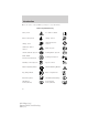
Introduction These are some of the symbols you may see on your vehicle.
Introduction Vehicle Symbol Glossary Power Windows Front/Rear Power Window Lockout Child Safety Door Lock/Unlock Interior Luggage Compartment Release Panic Alarm Engine Oil Engine Coolant Engine Coolant Temperature Do Not Open When Hot Battery Avoid Smoking, Flames, or Sparks Battery Acid Explosive Gas Fan Warning Power Steering Fluid Maintain Correct Fluid Level Service Engine Soon Engine Air Filter Passenger Compartment Air Filter Jack Check Fuel Cap Low Tire Pressure Warning MAX MIN
Instrument Cluster WARNING LIGHTS AND CHIMES Base instrument cluster with standard measure shown; metric similar OFF 5 100 120 6 4 80 7 3 60 140 180 200 160 220 140 120 100 80 2 F 40 60 40 20 0 km/h 1 0 20 E 0 MPH Optional instrument cluster with standard measure shown; metric similar 100 120 140 80 180 200 60 160 140 120 220 100 80 40 60 40 20 0 km/h 20 MPH 0 OFF Warning lights can alert you to a vehicle condition that may become serious enough to cause extensive repairs.
Instrument Cluster Many lights will illuminate when you start your vehicle to make sure the indicators work. If any light remains on after starting the vehicle, refer to the respective system warning light for additional information. Note: Some warning lights are reconfigurable telltale (RTT) indicators. These indicators display in the message center and function the same as a warning light but does not display on startup.
Instrument Cluster Brake system warning light: To ! P confirm the brake system warning light is functional, it will BRAKE momentarily illuminate when the ignition is turned on when the engine is not running, or in a position between on and start, or by applying the parking brake when the ignition is turned on. If the brake system warning light does not illuminate at this time, contact your authorized dealer as soon as possible.
Instrument Cluster Charging system (RTT): Illuminates when the battery is not charging properly. If it stays on while the engine is running, there may be a malfunction with the charging system. Contact your authorized dealer as soon as possible. This indicates a problem with the electrical system or a related component. Engine oil pressure (RTT): Illuminates when the oil pressure falls below the normal range, refer to Engine oil in the Maintenance and Specifications chapter.
Instrument Cluster Grade assist (RTT) (if equipped): Illuminates when grade assist is turned on. Speed control (RTT): The speed control system indicator light changes color to indicate what mode the system is in: • On (gray light): Illuminates when the speed control system is turned on. Turns off when the speed control system is turned off. • Engaged (green light): Illuminates when the speed control system is engaged. Turns off when the speed control system is disengaged.
Instrument Cluster Low washer fluid (RTT): Illuminates when the windshield washer fluid is low. Engine coolant temperature (RTT): Illuminates when the engine coolant temperature is high. Stop the vehicle as soon as possible, switch off the engine and let cool. Refer to Engine coolant in the Maintenance and Specifications chapter. WARNING: Never remove the coolant reservoir cap while the engine is running or hot.
Instrument Cluster GAUGES Base cluster shown in standard measure–metric similar 2 1 3 5 100 120 6 4 80 7 3 60 140 180 200 160 220 140 120 100 80 2 F 40 60 40 20 0 km/h 1 0 E 20 0 MPH 4 1. Tachometer: Indicates the engine speed in revolutions per minute. Driving with your tachometer pointer continuously at the top of the scale may damage the engine. 2. Multifunction display: This displays the engine coolant temperature, odometer and trip meter.
Instrument Cluster The engine coolant temperature gauge can be enabled or disabled. See Base message center in this chapter for information on changing the display settings. • AWD gauge (if equipped and enabled): Indicates AWD status. See All-Wheel Drive (Awd) system in the Driving chapter for information. 3. Speedometer: Indicates the current vehicle speed. 4. Fuel gauge: Indicates approximately how much fuel is left in the fuel tank (when the ignition is in the on position).
Instrument Cluster 3. Infotainment display: This display is used for the entertainment, phone, navigation and climate systems. See the MyFord Touch™ supplement for more information. BASE MESSAGE CENTER (IF EQUIPPED) WARNING: Driving while distracted can result in loss of vehicle control, accident and injury. Ford strongly recommends that drivers use extreme caution when using any device or feature that may take their focus off the road. Your primary responsibility is the safe operation of the vehicle.
Instrument Cluster Main menu Scroll up/down to highlight one of the options, then press the right arrow key or OK to enter into that menu option. Press the left arrow key as needed to exit back to the main menu. Trip 1 or 2 Trip Odometer — shows the accumulated trip distance. Trip Timer — shows the elapsed trip time. This timer will stop when the vehicle is turned off and will restart when the vehicle is restarted.
Instrument Cluster Driver Assist Display Convenience Settings Traction Control Blind Spot Collision Warning Sensitivity (if MyKey is programmed) Chimes Warning Cross Traffic Rear Park Aid Trailer Sway Language English, Español Units Distance Autolamp Delay Compass Determine which magnetic zone you are in for your geographic location by referring to the zone map.
Instrument Cluster Convenience (cont’d) Settings (cont’d) DTE Calculation Normal or Towing Easy Entry/Exit Locks Autolock or On or Off Autounlock Remote Unlock All Doors or Driver First Oil life Reset Set 10-100% Power Liftgate Switch Enabled or Disabled Remote Start Climate Control Heater – A/C Auto or Last Setting Climate Control Steering Wheel Auto or Off Climate Control Front Defrost Auto or Off Climate Control Rear Defrost Auto or Off Climate Control Driver Seat Auto or Off Climate Control Passenger S
Instrument Cluster MyKey System Reset Settings Create MyKey Traction Control Max Speed Speed Warning (cont’d) Hold OK to Create MyKey Always On or User Selectable 80 MPH (130 km/h) or Off 45 mph (75 km/h), 55 mph (90 km/h), 65 mph (105 km/h) or Off Volume Limiter Clear MyKeys Hold OK to Clear MyKeys Hold OK to Factory Default Reset System to Factory Default System Check* Oil Life Washer Fluid Doors Liftgate Blind spot Cross Traffic Brakes Fuel The number of warnings will be listed first.
Instrument Cluster Types of messages and warnings: • Some messages will appear briefly to inform you of something you may need to take action on or be informed of. • Some messages will appear once and then again when the vehicle is restarted. • Some messages will reappear after clearing or being reset if a problem or condition is still present and needs your attention. • Some messages can be acknowledged and reset by pressing OK.
Instrument Cluster SERVICE ADVANCETRAC — Displayed when the AdvanceTrac威 system has detected a condition that requires service. Contact your authorized dealer as soon as possible. CHECK CHARGING SYSTEM — Displayed when the charging system needs servicing. If the warning stays on or continues to come on, contact your authorized dealer as soon as possible. SHIFT TO PARK — Displayed when the start/stop button is pressed to shut off the engine with the shift select lever in any position other than P (Park).
Instrument Cluster BUCKLE UP TO UNMUTE AUDIO — Displayed when a MyKey™ is in use and Belt-Minder威 is activated. Refer to MyKey™ in the Locks and Security chapter for more information. REMOVE OBJECTS NEAR PASS SEAT — Displayed when objects are by the passenger seat. After the objects are moved away from the seat, if the warning stays on or continues to come on contact your authorized dealer as soon as possible. TRACTION CONTROL OFF — Displayed when the traction control has been disabled by the driver.
Instrument Cluster NO KEY DETECTED (if equipped) — Displayed if the intelligent access key is not detected by the system in the following three scenarios: •When the start/stop button is pressed in an attempt to either start the engine or cycle through the ignition states. •When the engine is running and a door is opened then closed. •When the vehicle’s speed exceeds 10 mph (16 km/h) for the first time after starting. Refer to Push button start system in the Driving chapter for more information.
Instrument Cluster CROSS TRAFFIC NOT AVAILABLE SENSOR BLOCKED (if equipped) — Displayed when the blind spot information system/cross traffic alert system sensors are blocked. See Blind Spot Information System (BLIS威) with Cross Traffic Alert in the Driving chapter. CROSS TRAFFIC SYSTEM FAULT (if equipped) — Displayed when a fault with the cross traffic alert system has occurred. Contact your authorized dealer as soon as possible.
Instrument Cluster The message center display is located in the instrument cluster. Use the left steering wheel controls to navigate through the message center. • Press the up/down arrow buttons to move up/down through the message center choices. • Press the left/right arrow buttons to move left/right through the message center choices. • Press the OK button to select highlighted options and confirm choices/messages.
Instrument Cluster Menu Control: You can choose a different menu control operation to suite your needs. In any screen which shows these category icons (other than the Main menu screen) and: • Standard is set– then scrolling up and down will scroll through the main categories. • Memory on is set– then scrolling up and down will scroll through the last selected sub-category/screen within a main category.
Instrument Cluster • Fuel gauge: Indicates approximately how much fuel is left in the fuel tank. The fuel gauge may vary slightly when the vehicle is in motion or on a grade. When the fuel level becomes low (50 miles [80 km] to empty), the level indicator will change to amber. When the fuel level becomes critically low (0 miles [0 km] to empty), the level indicator will change to red. Note: When a MyKey™ is in use, low fuel warnings will display earlier .
Instrument Cluster Intelligent all-wheel drive (AWD) (if equipped) + other gauges For a description of the other gauges, see the descriptions listed previously. • Intelligent all-wheel drive: shows the AWD mode that the vehicle is in. Refer to All-Wheel Drive (AWD) system in the Driving chapter. Intelligent AWD 6 F 4 RPM + 1000 2 E 0 01234.5mi SelectShift Automatic™ transmission (SST) This feature allows you to manually shift gears.
Instrument Cluster Trip 1 & 2 Press the right arrow on the left steering wheel mounted button when trip 1 & 2 is selected. The boxes in the upper right corner of the screen indicate that there are multiple screens that you can navigate through. Each press of the right arrow will navigate to the next screen until the last screen is reached. The white highlighted box indicates which of the screens you are currently viewing: Choose the standard or enhanced display.
Instrument Cluster Press OK to pause the Trip 1 or 2 screen. Press again to un-pause. Press and hold OK to reset the currently displayed trip information. Fuel Economy Press the right arrow on the left steering wheel mounted button when fuel economy is selected. The boxes in the upper right corner of the screen indicate that there are multiple screens that you can navigate through. Each press of the right arrow will navigate to the next screen until the last screen is reached.
Instrument Cluster To determine your average highway fuel economy, do the following: 1. Drive the vehicle at least 5 miles (8 km) with the speed control system engaged to display a stabilized average. 2. Record the highway fuel economy for future reference. It is important to reset fuel economy after setting the speed control to get accurate highway fuel economy readings. For more information refer to Essentials of good fuel economy in the Maintenance and Specifications chapter.
Instrument Cluster Locks Menu Control Oil Life Reset Power Liftgate Remote Start Wipers Create MyKey Traction Control Max Speed Speed Warning Volume Limiter Clear MyKeys Vehicle Autolock, On (default on key cycle) / Off Autounlock On (default on key cycle) / Off Remote All doors / Driver’s door (default Unlocking setting) Standard / Memory On Set to 10–100% Enable / Disable Auto / Last Climate Control Heater – A/C Settings (using this feature allows Front Defrost Auto / Off you to select different clim
Instrument Cluster Gauge Display Trip Display Display Fuel Gauge / Fuel gauge + Tachometer Standard / Enhanced Language English / Español / Français Distance Temperature Units Miles & Gallons / Kilometers & Liters Fahrenheit (°F) / Celsius (°C) Restore Defaults Hold OK to Restore Settings to Factory Defaults Information In this mode, you can view different vehicle system information and perform a system check.
Instrument Cluster System warnings and status messages System warnings alert you to possible problems or malfunctions in your vehicle’s operating systems. In the event of a multiple warning situation, the message center will cycle the display to show all warnings by displaying each one for four seconds. The message center will display the last selected feature if there are no more warning messages.
Instrument Cluster CHECK CHARGING SYSTEM — Displayed when the charging system needs servicing. If the warning stays on or continues to come on, contact your authorized dealer as soon as possible. PARK BRAKE ENGAGED — Displayed when the parking brake is set, the engine is running and the vehicle is driven more than 3 mph (5 km/h). If the warning stays on after the parking brake is released, contact your authorized dealer as soon as possible.
Instrument Cluster TIRE PRESSURE SENSOR FAULT — Displayed when a tire pressure sensor is malfunctioning, or your spare tire is in use. For more information on how the system operates under these conditions, refer to Understanding Your Tire Pressure Monitoring System (TPMS) in the Tires, Wheels and Loading chapter. If the warning stays on or continues to come on, contact your authorized dealer as soon as possible. BUCKLE UP TO UNMUTE AUDIO — Displayed when a MyKey™ is in use and Belt-Minder威 is activated.
Instrument Cluster MAX NUMBER OF KEYS PROGRAMMED — Displayed during spare key programming when the maximum number of keys have been programmed. MYKEY ACTIVE DRIVE SAFELY — Displayed when MyKey™ is active. MYKEY NOT CREATED — Displayed during key programming when MyKey™ cannot be programmed.
Instrument Cluster CRUISE CONTROL AUTOMATIC BRAKING TURNED OFF (if equipped) — Displayed when adaptive cruise control automatic braking is turned off. ADAPTIVE CRUISE MALFUNCTION (if equipped) — Displayed when a radar malfunction is preventing the ACC from engaging. ADAPTIVE CRUISE NOT AVAILABLE (if equipped) — Displayed when conditions exist such that the adaptive cruise cannot function properly.
Instrument Cluster CROSS TRAFFIC VEHICLE COMING FROM LEFT (if equipped) — Displayed when the blind spot information system with cross traffic alert (CTA) system is operating and senses a vehicle. See Blind Spot Information System (BLIS威) with Cross Traffic Alert in the Driving chapter. CROSS TRAFFIC VEHICLE COMING FROM RIGHT (if equipped) — Displayed when the blind spot information system with cross traffic alert (CTA) system is operating and senses a vehicle.
Entertainment Systems MYFORD™ SYSTEM (IF EQUIPPED) WARNING: Driving while distracted can result in loss of vehicle control, accident and injury. Ford strongly recommends that drivers use extreme caution when using any device or feature that may take their focus off the road. Your primary responsibility is the safe operation of the vehicle.
Entertainment Systems 3. Use the center control in the same manner you would a joystick — press / to move up/down / to move in menus or press out of or into a menu. When these options are available, icons will appear on the screen. 4. Press OK on the center control to make or confirm selections. Note: You can also use the OK and arrow buttons on the right side of your steering wheel to make the same selections you would with the center control. Setting the Clock • Press CLOCK.
Entertainment Systems • Select the Mute soft key to mute the playing media. Press again to return to the playing media. • Press / to seek to the previous/next station. • Select the AST (Autostore) soft key to activate the auto store feature. Autostore allows you to store the 10 strongest local stations available from the AM and FM frequency band. Press and hold the AST soft key and follow the screen prompts.
Entertainment Systems • RBDS/RDS Text: Select to turn Radio Broadcast Digital Signal text on to view additional broadcast data.Note: This feature defaults to off, but it must be turned on in order for you to choose and set a category. When this feature is activated, all of your text will scroll on one line. To see all of your text, press the Info soft key.
Entertainment Systems • Select the ‘Replay’ soft key to replay audio on the current channel. You can replay approximately 45 minutes of audio as long as you have remained tuned to the current station. If you change stations, the previous audio will be erased. While in replay mode, you can: • Press and release / to advance to the previous /next song . • Press and hold / to advance to reverse or fast forward in the current track. • Press / to play / pause the audio.
Entertainment Systems • Alerts: Select this to create an alert for a particular song or artist or team. The system will then alert you when it is playing on another channel. From this screen you can also maintain alerts, enable/disable and delete alerts from your list. You can save up to 20 alerts. If you attempt to save an alert and your list is full, the system will prompt you to delete one.
Entertainment Systems You will hear an audio mute when there is a satellite radio signal interference. Your display may show Acquiring . . . to indicate the interference. Satellite radio electronic serial number (ESN): You will need your ESN to activate, modify or track your satellite radio account. The ESN is found on the System Information Screen (SR ESN:XXXXXXXXXXXX). To access your ESN, press MENU > SIRIUS >Show ESN or tune to channel 0.
Entertainment Systems Radio Display No Signal Condition Loss of signal from the SIRIUS威 satellite or SIRIUS威 tower to the vehicle antenna. Possible action The signal is currently being blocked. When you move into an open area, the signal should return. No action required. The Updating Update of channel programming in process may take up to three minutes. progress.
Entertainment Systems CD Options Press MENU > CD Options to access: • Scan All: Press to hear a brief selection of all tracks on the current disc. • Scan Folder: Available when playing an MP3 disc. Select for a brief sampling of all the music in the current folder. • CD compression: Brings soft and loud CD passages together for a more consistent listening level. Audio settings Press MENU > Audio Settings to access: • Spd. Comp. Vol: Scroll to select Speed Compensated Volume and press OK to enter the menu.
Entertainment Systems Auxiliary input jack (line in) WARNING: Driving while distracted can result in loss of vehicle control, accident and injury. Ford strongly recommends that drivers use extreme caution when using any device or feature that may take their focus off the road. Your primary responsibility is the safe operation of the vehicle.
Entertainment Systems Phone PHONE: Press to mute the playing media. Press again to return to the playing media. MYFORD TOUCH ™(IF EQUIPPED) WARNING: Driving while distracted can result in loss of vehicle control, accident and injury. Ford strongly recommends that drivers use extreme caution when using any device that may take their focus off the road. Your primary responsibility is the safe operation of the vehicle.
Climate Controls SINGLE ZONE MANUAL CLIMATE CONTROL (IF EQUIPPED) 9 1 8 2 7 3 6 4 5 Temperature conversion: To switch between Fahrenheit and Celsius: Press MENU > Display Settings > Temp. Setting. 1. A/C: Press to activate/deactivate air conditioning. Use with recirculated air to improve cooling performance and efficiency. A/C (defrost) engages automatically in MAX A/C, (floor/defrost). and (Recirculated air): Press to activate/deactivate air recirculation 2. in the vehicle.
Climate Controls 5. (Multifunction control): Press repeatedly to toggle through the settings and manually choose one of the following air distribution modes: • : Distributes air through the windshield defroster vents, de-mister vents, floor vents and rear seat floor vents. The system will automatically provide outside air to reduce window fogging. • : Distributes air through the instrument panel vents.
Climate Controls For maximum cooling performance in MAX A/C mode: 1. Select MAX A/C. 2. Move temperature control selector to the coolest setting. 3. Set the fan to the highest speed initially. As the interior starts to cool down, adjust the fan speed to maintain comfort. To aid in side window defogging/demisting in cold weather: 1. Select (panel/floor). 2. Select A/C. 3. Adjust the temperature control to maintain comfort. 4. Set the fan speed to the highest setting. 5.
Climate Controls 2. (Recirculated air): Press to activate/deactivate air recirculation in cabin. Recirculated air may reduce the amount of time to cool down the interior of the vehicle and may also help reduce undesired odors from reaching the interior of the vehicle. Recirculated air engages automatically when MAX A/C is selected or can be engaged manually in any airflow mode except (defrost). Recirculated air may turn off automatically in all airflow modes except MAX A/C to reduce fog potential. 3.
Climate Controls 11. Manual override controls: Press repeatedly to toggle through the settings and manually choose one of the following air distribution modes: • : Distributes air through the windshield defroster ducts, demister outlets, and the front and rear seat floor vents. The system will automatically provide outside air to reduce window fogging • : Distributes air through the instrument panel vents, demister vents, and the front and rear seat floor vents.
Climate Controls 1. A/C control: Press to activate/deactivate air conditioning. Use with recirculated air to improve cooling performance and efficiency. Engages automatically in AUTO, (defrost) and (floor/defrost). 2. MAX A/C: Distributes recirculated air through the instrument panel vents to cool the vehicle. This re-cooling of the interior air is more economical and efficient. Recirculated air may also help reduce undesirable odors from entering the vehicle.
Climate Controls 10. R (Rear defroster): Press to activate/deactivate the rear defroster. This button will also activate/deactivate the heated mirrors (if equipped). Refer to Rear window defroster later in this chapter for more information. (Defrost): Distributes outside air through the windshield 11. defroster vents and demister vents. Can be used to clear the windshield of fog and thin ice. Press this button again to return to the previous air flow selection.
Climate Controls 2. (Recirculated air): Touch to activate/deactivate air recirculation in the vehicle. Recirculated air may reduce the amount of time needed to cool down the interior of the vehicle and may also help reduce undesired odors from reaching the interior of the vehicle. Recirculated air engages automatically when MAX A/C is selected or can be engaged manually in any airflow mode except (defrost).
Climate Controls MyTemp: Touch and hold to save the desired temperature for MyTemp. To access this setting again, simply touch the indicator. The MyTemp feature can be used to store and recall a preset driver’s temperature. This feature is provided so this temperature can be quickly adjusted to a frequently used setting with a single button touch.
Climate Controls To aid in side window defogging/demisting in cold weather: 1. Select . 2. Select A/C. 3. Adjust the temperature control to maintain comfort. 4. Set the fan to the highest speed. 5. Direct the outer instrument panel vents toward the side windows. To increase airflow to the outer instrument panel vents, close the vents located in the middle of the instrument panel. Touchscreen features (if equipped) Press the lower right corner on the touchscreen to access these features.
Climate Controls 4. (Recirculated air): Press to activate/deactivate air recirculation in the vehicle. Recirculated air may reduce the amount of time needed to cool down the interior of the vehicle and may also help reduce undesired odors from reaching the interior of the vehicle. Recirculated air engages automatically when MAX A/C is selected on can be engaged manually in any airflow mode except (defrost). Recirculated air may turn off in all airflow modes except MAX A/C to reduce fog potential. 5.
Climate Controls • : Distributes air through the demister vents, floor vents and rear seat floor vents. To return to full automatic control, press AUTO. 11. Driver settings: • Press the red arrow to increase the temperature and press the blue arrow to decrease the temperature. • Press to control the heated seat (if equipped). Refer to Heated seats in the Seat and Safety Restraints chapter. • Press and hold MyTemp to select a temperature you would like the vehicle to remember and maintain for you.
Climate Controls *Note: If you have said “Temperature”, you can then say any of the following commands: • High • Low • <15.5–29.5> degrees • <60–85> degrees For more information on your touchscreen system, refer to the MyFord Touch™ / MyLincoln Touch™ supplement. REAR WINDOW DEFROSTER R The rear defroster control is located on the climate control panel and works to clear the rear window of fog and thin ice. The engine must be running to operate the rear window defroster.
Climate Controls For cold weather conditions: • The interior cabin will be heated to 72°F (22°C). • The heated seats (if equipped) will be set to high. • Rear defrost/heated mirrors (if equipped) will be activated. For moderate weather conditions: • The interior cabin will be heated, cooled, or off, based upon the previous operating state (last ignition-on cycle). • Heated/cooled seats (if equipped) will be deactivated. • Rear defrost/heated mirrors (if equipped) will be deactivated.
Lights HEADLAMP CONTROL Turns the lamps off. Turns on the parking lamps, instrument panel lamps, license plate lamps and tail lamps. A Turns the headlamps on. Autolamp control (if equipped) The autolamp system provides light sensitive automatic on-off control of the exterior lights normally controlled by the headlamp control. • To turn autolamps on, rotate the . control to A • To turn autolamps off, rotate the control from the autolamp position.
Lights 3. Rotate the headlamp control to the off position. 4. Turn the vehicle on. 5. Turn the vehicle off. 6. Turn the headlamp control to the autolamp position (the headlights should turn on). 7. Turn the headlamp control to the off position when the desired delay time (up to three minutes) has been reached. High beams Pull the lever fully past the detent to activate. Pull the lever fully again to deactivate. Flash-to-pass Pull toward you slightly to activate and release to deactivate.
Lights PANEL DIMMER CONTROL Use to adjust the brightness of the instrument panel and all applicable lit components in the vehicle during headlamp and parking lamp operation. • Tap the top or bottom of the control to brighten/dim all interior lit components incrementally, or • Press and hold the top or bottom of the control until the desired lighting level is reached.
Lights • (1) 8 feet (2.4 meters) • (2) Center height of lamp to ground • (3) 25 feet (7.6 meters) • (4) Horizontal reference line 2. Measure the height of the headlamp bulb center from the ground and mark an 8 foot (2.4 meter) horizontal reference line on the vertical wall or screen at this height. 3. Turn on the low beam headlamps to illuminate the wall or screen and open the hood. To see a clearer light pattern for adjusting, you may want to block the light from one headlamp while adjusting the other.
Lights 4. Locate the vertical adjuster on each headlamp. Using a Phillips #2 screwdriver, turn the adjuster either clockwise (to adjust down) or counterclockwise (to adjust up). The horizontal edge of the brighter light should touch the horizontal reference line. 5. Close the hood and turn off the lamps. HORIZONTAL AIM IS NOT REQUIRED FOR THIS VEHICLE AND IS NON-ADJUSTABLE. TURN SIGNAL CONTROL The turn signal lever does not mechanically lock in the upward or downward position when activated.
Lights INTERIOR LAMPS Front row map lamps (if equipped) To turn on the map lamps, press the outer edge of the clear lens. The front row map lamp lights when: • any door is opened. • the dome lamp button on the instrument panel is activated. • the remote entry controls are pressed and the ignition is off. Map/dome lamp (if equipped) The dome lamp lights when: • any door is opened. • the dome lamp button on the instrument panel is activated.
Lights BULB REPLACEMENT Lamp assembly condensation Exterior lamps are vented to accommodate normal changes in pressure. Condensation can be a natural by-product of this design. When moist air enters the lamp assembly through the vents, there is a possibility that condensation can occur when the temperature is cold. When normal condensation occurs, a thin film of mist can form on the interior of the lens. The thin mist eventually clears and exits through the vents during normal operation.
Lights Function Number of bulbs Rear turn lamp 2 Stop/tail/sidemarker lamp 4 Trade number 3757NAK (amber) 3157K LCP or 3157K 921 168 LED W5W Backup lamp 2 License plate lamp 2 * High-mount brake lamp N/A Map lamp 2 Second row dome/reading 3 578 lamp Rear courtesy lamp 1 578 Visor vanity lamp 2 37 All replacement bulbs are clear in color except where noted. To replace all instrument panel lights - see your authorized dealer. * To replace these lamps - see your authorized dealer.
Lights 3. Remove the bulb cover. 4. Turn the bulb holder counterclockwise and remove it. 5. Disconnect the electrical connector. WARNING: Handle a halogen headlamp bulb carefully and keep out of children’s reach. Grasp the bulb only by its plastic base and do not touch the glass. The oil from your hand could cause the bulb to break the next time the headlamps are operated. 6. Reverse the procedure to install the new bulb.
Lights Replacing HID headlamp bulbs (if equipped) The low beam headlamps on your vehicle use a “high intensity discharge” source. These lamps operate at a high voltage. When the bulb is burned out, the bulb and starter capsule assembly must be replaced by your authorized dealer. Replacing front parking lamp/turn signal bulbs 1. Make sure that the headlamp control is in the off position. 2. Open the hood. 3. Reach over the front bolster. 4.
Lights Replacing tail/stop/turn/sidemarker/backup lamp bulbs The tail/stop/turn/sidemarker/backup lamp bulbs are located in the same area of the tail lamp assembly, one below the other. Follow the same steps to replace these bulbs: 1. Make sure the headlamp switch is in the off position, then open the liftgate to expose the lamp assembly bolts. 2. Remove the two bolts from the lamp assembly. 3.
Lights Replacing license plate lamp bulbs 1. Make sure the headlamp switch is in the off position. 2. Press the lever and carefully pry the license plate lamp assembly (located above the license plate) from the liftgate. 3. Rotate the bulb socket counterclockwise and remove from lamp assembly. 4. Pull bulb straight out of socket and push in the new bulb. 5. Install the bulb socket into the lamp assembly and rotate clockwise. 6. To install, carefully press the lamp assembly into the liftgate.
Driver Controls WINDSHIELD WIPERS Windshield wiper: Rotate the end of the control away from you to increase the speed of the wipers; 2 1 rotate towards you to decrease the 0 speed of the wipers. Speed dependent wipers (if equipped): When the wiper control is set to any of the interval settings except the longest pause setting, the pause time between wiping will automatically adjust with the vehicle speed. The faster your vehicle is travelling the shorter the pause time between wipes will become.
Driver Controls Windshield washer: Press the end of the stalk: 2 • briefly: causes a single swipe of 1 0 the wipers without washer fluid. • a quick press and hold: the wipers will swipe three times with washer fluid. • a long press and hold: the wipers and washer fluid will be activated for up to ten seconds. Note: Do not operate the washer when the washer reservoir is empty. This may cause the washer pump to overheat. Check the washer fluid level frequently.
Driver Controls For rear wash cycle, rotate (and hold as desired) the rear wiper/washer control to either position. From either position, the control will automatically return to the 2 or O (off) position. Reverse wiper feature: The rear wiper will be automatically activated in an intermittent setting when shifting into R (Reverse) if the front wipers are activated. This feature may be enabled/disabled through the message center. Refer to Message center in the Instrument Cluster chapter.
Driver Controls ILLUMINATED VISOR MIRROR (IF EQUIPPED) Lift the mirror cover to turn on the visor mirror lamp. Slide-on-rod feature Rotate the visor towards the side window and extend it rearward for additional sunlight coverage. Note: To stow the visor back into the headliner, visor must be retracted before moving it back towards the windshield. OVERHEAD CONSOLE The appearance of your vehicle’s overhead console will vary according to your option package.
Driver Controls CENTER CONSOLE Your vehicle may be equipped with a variety of console features. These include: 1. Cupholders 1 2. Two pen/pencil holders, travel 2 tissue pack holder, and business card/paper holder (if equipped, located on underside of console lid). 3. Rear power point 4 4. Utility compartment with in-bin 3 power point, audio input jack, and a removable coin holder tray (two grooves on tray slide onto tracks in main bin). WARNING: Use only soft cups in the cupholder.
Driver Controls To prevent the fuse from being blown, do not use the power point(s) over the vehicle capacity of 12V DC/180W. If the power point or cigar lighter socket is not working, a fuse may have blown. Refer to Fuses and relays in the Roadside Emergencies chapter for information on checking and replacing fuses. To have full capacity usage of your power point, the engine is required to be running to avoid unintentional discharge of the battery.
Driver Controls One-touch up or down (driver’s window only) This feature allows the driver’s window to open or close fully without holding the control down. To operate one-touch down, press the switch completely down to the second detent and release quickly. The window will open fully. Momentarily press the switch to any position to stop the window operation. To operate one-touch up, pull the switch completely up to the second detent and release quickly. The window will close fully.
Driver Controls INTERIOR MIRROR The interior rear view mirror has two pivot points on the support arm which lets you adjust the mirror up or down and from side to side. WARNING: Do not adjust the mirror while the vehicle is in motion. Automatic dimming interior rear view mirror (if equipped) The interior rear view mirror has an auto-dimming function.
Driver Controls Memory mirrors (if equipped) The power side view mirror positions are saved when doing a memory set and can be recalled along with the vehicle personality features when a memory position is selected through the remote entry transmitter, keyless entry keypad or memory switch on the driver’s door. Refer to Front seating in the Seating and Safety Restraints chapter.
Driver Controls SPEED CONTROL (IF EQUIPPED) With speed control set, you can maintain a set speed without keeping your foot on the accelerator pedal. WARNING: Do not use the speed control in heavy traffic or on roads that are winding, slippery or unpaved. Using speed control The speed controls are located on the steering wheel. The following buttons work with speed control: SET: Press to set a speed or to increase or decrease the set speed. RES (Resume): Press to resume the set speed.
Driver Controls Resuming a set speed Press and release RES. This will automatically return the vehicle to the previously set speed. Increasing speed while using speed control To set a higher speed: • Press SET upward and hold until you get to the desired speed, then release. You can also use SET to operate the tap-up function. Press SET upward and release to increase the vehicle set speed in 1 mph (1.6 km/h) increments.
Driver Controls WARNING: Always pay close attention to changing road conditions, especially when using adaptive cruise control. Adaptive cruise control cannot replace attentive driving. Failing to follow any of the warnings below or failing to pay attention to the road may result in a collision, serious injury or death. WARNING: Adaptive cruise control is not a collision warning or avoidance system.
Driver Controls Setting adaptive cruise control 1. Press and release ON. The message center will display the ACC indicator light, current gray gap setting and SET. 2. Accelerate to the desired speed. 3. Press SET upward and release. The vehicle speed will be stored in the memory and the message center will display a green ACC indicator light, current gap setting and desired set speed. 4. Take your foot off the accelerator pedal. 5.
Driver Controls If the ACC system predicts that its maximum braking level will not be sufficient, an audible warning will sound while the ACC continues to brake. This is accompanied by a heads-up display; a red warning bar illuminating on the windshield. The driver should take immediate action. Note: The brakes may emit a sound when they are being modulated by the adaptive cruise control system. WARNING: Adaptive cruise control only warns of vehicles detected by the radar sensor.
Driver Controls Disengaging adaptive cruise control Press the brake pedal or press CNCL to disengage the adaptive cruise control. The last set speed will be displayed with a strikethrough. Disengaging the adaptive cruise control will not erase your previous set speed. Overriding adaptive cruise control WARNING: Whenever the driver is overriding the ACC by pressing the accelerator pedal, the ACC will not automatically apply the brakes to maintain separation from any vehicle ahead.
Driver Controls Low speed automatic cancellation ACC is not functional at vehicle speeds below 16 mph (26 km/h). Once the vehicle speed drops below 16 mph (26 km/h), an audible alarm will sound and the automatic braking will be released. Hilly condition usage It is recommended that the driver select a lower gear position when ACC is active in situations such as prolonged downhill driving on steep grades (i.e., driving in mountainous areas).
Driver Controls • With vehicles that edge into your lane. These vehicles can only be detected once they have moved fully into your lane. • There may be issues with the detection of vehicles in front when driving into and coming out of a bend or curve in the road. In these cases ACC may brake late or unexpectedly. The driver should stay alert and intervene when necessary. ACC Not Available Several conditions exist which can cause ACC to deactivate or prevent ACC from activating when requested.
Driver Controls Blocked sensor If a message regarding a blocked sensor is displayed, the radar signals from the sensor have been obstructed. The sensor is located behind a fascia cover near the driver side of the lower grille. When the radar signals are obstructed, a vehicle ahead cannot be detected and the ACC will not function. The following table lists possible causes and actions for this message being displayed.
Driver Controls WARNING: Do not use tires sizes other than those recommended because this can affect the normal operation of ACC. Failing to do so may result in a loss of vehicle control, which could result in serious injury. Switching to normal cruise control You can manually change from adaptive cruise control (ACC) to normal cruise control through the message center. Refer to Message center in the Instrument Cluster chapter.
Driver Controls Navigation/SYNC威 system hands-free control features (if equipped) Press to active the voice recognition feature. Refer to Voice recognition feature in the MyFord Touch™ / MyLincoln Touch™ supplement. to access phone features. Press Refer to Phone features in the MyFord Touch™ / MyLincoln Touch™ supplement. VOL SEEK Cluster display control features If equipped with the MyFord™ system, this control functions the same as the center control on the faceplate.
Driver Controls PANORAMIC VISTA ROOF™ AND POWER SUNSHADES (IF EQUIPPED) The panoramic Vista Roof™ and power sunshade controls are located on the overhead console. WARNING: Do not let children play with the panoramic Vista Roof™ and power sunshade or leave children unattended in the vehicle. They may seriously hurt themselves.
Driver Controls To close the panoramic Vista Roof™ and power sunshades: Pull the control down and release. The glass panel will stop at the “express close” position. Firmly pull the control again and hold to fully close the Vista Roof™. Pull the control down and release to close the sunshades to the “express close” position. Firmly pull the control again and hold to fully close the front and rear sunshades. To vent the panoramic Vista Roof™: From the closed position, press and release the TILT control.
Driver Controls model manufactured before April 1, 1982). A garage door which cannot detect an object, signaling the door to stop and reverse, does not meet current U.S. federal safety standards. For more information, contact HomeLink威 at: www.homelink.com or 1–800–355–3515. Retain the original transmitter for use in other vehicles as well as for future programming procedures (i.e. new HomeLink威 equipped vehicle purchase).
Driver Controls • If the indicator light blinks rapidly for two seconds and then turns to a constant light continue with “Programming” Steps 4 through 6 to complete programming of a rolling code equipped device (most commonly a garage door opener). 4. At the garage door opener receiver (motor-head unit) in the garage, locate the “learn” or “smart” button (usually near where the hanging antenna wire is attached to the unit). 5. Firmly press and release the “learn” or “smart” button.
Driver Controls Operating the HomeLink姞 Wireless Control System To operate, simply press and release the appropriate HomeLink威 button. Activation will now occur for the trained product (garage door, gate operator, security system, entry door lock, or home or office lighting etc.). For convenience, the hand-held transmitter of the device may also be used at any time. In the event that there are still programming difficulties, contact HomeLink威 at www.homelink.com or 1–800–355–3515.
Driver Controls POSITIVE RETENTION FLOOR MAT WARNING: Do not install additional floor mats on top of the factory installed floor mats as they may interfere with the accelerator or the brake pedals. Position the floor mat so that the eyelet is over the retention post and press down to lock in. Make sure that the mat does not interfere with the operation of the accelerator or the brake pedal. To remove the floor mat, reverse the installation procedure.
Driver Controls WARNING: Make sure that the liftgate is closed to prevent exhaust fumes from being drawn into the vehicle. This will also prevent passengers and cargo from falling out. If you must drive with the liftgate door open, keep the vehicle well ventilated so outside air comes into the vehicle. Liftgate ajar signal If the liftgate is not fully latched, you will receive a “LIFTGATE AJAR” message on the instrument panel. If you see this message, check the liftgate door to ensure it is fully latched.
Driver Controls If the liftgate reverses and starts to close after an open request, a fast continuous chime indicates excessive load on the gate or a possible strut failure. If any excessive load is removed and you still have a faster chime, have the system serviced immediately by your authorized dealer. Do not attempt to manually force the liftgate to travel faster than the power system will permit. This will activate the obstacle detection feature.
Driver Controls To power open or close the liftgate with the transmitter: twice within three seconds to open the liftgate. Refer to Press Remote entry system in the Locks and Security chapter. To power open the liftgate with outside liftgate control button: 1. Unlock the liftgate with the transmitter or power door unlock control. If the intelligent access transmitter (if equipped) is within 3 feet (1 meter) of the liftgate, the liftgate will unlock when you press the liftgate release button. 2.
Driver Controls To manually operate the liftgate: 1. Disable the liftgate power function. Refer to the Message center in the Instrument Cluster chapter. 2. Open and close the liftgate as you would a standard liftgate. Refer to Manual liftgate in this chapter. Note: In case of operation in extreme cold -40°F (-40°C), or on extreme inclines, manual operation of the liftgate is suggested. Obstacle detection The power liftgate system is equipped with an obstacle detection feature.
Driver Controls CARGO AREA FEATURES Cargo management system (if equipped) The cargo management system consists of storage compartments located in the floor of the rear cargo area. 1. To open, lift the release handle and the lid. 2. To close, lower the lid. Cargo net (if equipped) The cargo net secures lightweight objects in the cargo area. Attach the net to the loops and anchors provided. WARNING: This net is not designed to restrain objects during a collision.
Driver Controls Utility hook The utility hook can be used to hang small items such as grocery bags, etc. Do not hang more than 10 lb (4.5 kg) on the hook. ROOF RACK SYSTEM (IF EQUIPPED) Loads should never be placed directly on the roof panel. For proper function of the roof rack system, loads must be placed directly on crossbars affixed to the roof rack side rails. Your vehicle may be equipped with factory-installed crossbars.
Locks and Security KEYS Integrated keyhead transmitters (IKTs) (if equipped) Your vehicle may be equipped with two integrated keyhead transmitters (IKTs). The key blade functions as a programmed key which starts the vehicle and unlocks/locks the driver’s door. The transmitter portion functions as the remote entry transmitter. Your IKTs are programmed to your vehicle; using a non-programmed key will not permit your vehicle to start.
Locks and Security Intelligent Access Key (IA key) (if equipped) Your vehicle may be equipped with two intelligent access keys which operate the power locks and the remote start system. The IA key must be in the vehicle to activate the push button start system. The IA key also contains a removable mechanical key blade that can be used to unlock the driver door. To release the mechanical key blade, slide the release on the back of the transmitter and pull the blade out.
Locks and Security MYKEY™ The MyKey™ feature allows you to program a restricted driving mode to promote good driving habits. All but one of the keys programmed to the vehicle can be activated as a MyKey™. The key will remain restricted until MyKey™ is cleared. Any remaining keys are referred to as an “administrator key” or admin key. The admin key can be used to create a MyKey™, program optional MyKey™ settings, and clear the MyKey™ feature.
Locks and Security Create a MyKey™ To program MyKey™ on one of the keys programmed to the vehicle, insert the key that you want to make a MyKey™ into the ignition. For vehicles equipped with push button start, put the intelligent access key in the backup slot with brand logo facing up; see the Driving chapter for the location of the backup slot. Turn the ignition on. Use the message center buttons to do the following: 1.
Locks and Security Check MyKey™ system status The vehicle’s message center information menu will provide the status of the following MyKey™ parameters: • MYKEY MILES (km) — This odometer only tracks distance when a MyKey™ is used. If distance does not accumulate as expected, then the MyKey™ is not being used by the intended user. The only way to reset this odometer to zero is by clearing MyKey™. If this odometer is lower than the last time you checked, then the MyKey™ system has been recently cleared.
Locks and Security To program a non Ford-approved remote start system as MyKey™, do the following: 1. Enter the vehicle and close all doors. 2. Remote start the vehicle using a non Ford-approved remote start fob. 3. Follow steps 1-4 in the Create a MyKey™ section. Vehicles equipped with an intelligent access key (push button start) • It is not possible to program any remote start system as MyKey™ on vehicles equipped with intelligent access key (push button start).
Locks and Security Troubleshooting Condition Can’t create a MyKey™ Cannot program the MyKey™ optional settings Cannot clear MyKey™ Lost the only admin key Lost any key 120 2011 Edge (edg) Owners Guide, 2nd Printing USA (fus) Potential Causes • Key in the ignition is already a MyKey™. • Key in the ignition is the last remaining admin key (there always has to be at least one admin key). • Intelligent access key (if equipped) is not in the backup slot (for vehicles with push button start).
Locks and Security Condition I accidentally programmed all keys as MyKeys™ Potential Causes • Vehicle has a non Ford-approved remote start system that is recognized as an admin key. Refer to the Using MyKey™ with remote start systems section to reset all MyKeys™ as admin keys. No MyKey™ function • An admin intelligent access key is present at a push-and-start vehicle. • No MyKeys™ are programmed to the vehicle. Refer to Create a MyKey™ section.
Locks and Security POWER DOOR LOCKS • Press the doors. control to unlock all • Press the doors. control to lock all Smart unlocks for integrated keyhead transmitter (IKT) This feature helps to prevent you from locking yourself out of the vehicle if your key is still in the ignition.
Locks and Security When you open one of the front doors and you lock the vehicle using the driver or passenger power door lock control (with the vehicle not in P (Park) and the ignition off, or the ignition on), all doors will lock, then all doors will automatically unlock reminding you that the vehicle is not in P (Park) or the ignition is on.
Locks and Security Autounlock feature (if enabled) The autounlock feature will unlock all the doors when: • the ignition is on, all the doors are closed, and the vehicle has been in motion at a speed greater than 12 mph (20 km/h); • the vehicle has then come to a stop and the ignition is turned off or to accessory; and • the driver door is opened within 10 minutes of the ignition being turned off or to accessory.
Locks and Security CHILDPROOF DOOR LOCKS • When these locks are set, the rear doors cannot be opened from the inside. • The rear doors can be opened from the outside when the childproof door locks are set, but the doors are unlocked. The childproof locks are located on the rear edge of each rear door and must be set separately for each door. Setting the lock for one door will not automatically set the lock for both doors.
Locks and Security The transmitter allows you to: • remotely unlock the vehicle doors . • remotely lock all the vehicle doors . • remotely open the power liftgate (if equipped) . • remotely start/stop the vehicle (if equipped) . Refer to Remote start later in this section. • activate the personal alarm . • arm and disarm the perimeter anti-theft system. • operate the illuminated entry feature. Refer to Intelligent access in this section for more features.
Locks and Security To lock the doors, press and hold for half a second the lock area on either front door handle (black button on chrome handled doors or the small bump on painted door handles). Activating intelligent access at the liftgate: If your IA key is within 3 feet (1 meter) of the liftgate, you can activate your intelligent access system by pressing the exterior liftgate release button on the top of the liftgate pull-cup handle. The liftgate will release and open.
Locks and Security Car finder Press twice within three seconds. The horn will chirp and the turn lamps will flash. It is recommended that this method be used to locate your vehicle, rather than using the panic alarm. Sounding a panic alarm Press to activate the alarm. Press again or turn the ignition to on to deactivate. Note: The panic alarm will only operate when the ignition is off. Opening the power liftgate (if equipped) Press liftgate.
Locks and Security Programming the memory feature to the transmitter To activate this feature: 1. Move the driver seat and power mirrors to the desired positions using the associated controls. 2. Press and hold button 1 for five seconds. A tone will be heard after about two seconds confirming memory position has been set. Continue to hold until a second tone is heard after five seconds. 3. Within three seconds press 4. Wait 10 seconds, then press . . 5.
Locks and Security Replacing the battery The integrated keyhead transmitter (IKT) or intelligent access key (IA key) uses one coin type three-volt lithium battery CR2032 or equivalent. To replace the battery: Integrated keyhead transmitter (IKT) 1. Twist a thin coin in the slot near 1 the key ring to remove the battery cover (1). 2 Note: Do not wipe off any grease on the battery terminals on the back surface of the circuit board. 3 2.
Locks and Security 2. Remove the old battery. Note: Please refer to local regulations when disposing of transmitter batteries. 3. Insert the new battery. Refer to the instructions inside the IA key for the correct orientation of the battery. Press the battery down to ensure that the battery is fully seated in the battery housing cavity. 4. Snap the battery cover back onto the transmitter and install the backup key.
Locks and Security Illuminated exit When all vehicle doors are closed, the ignition is turned off and the key is removed from the ignition (IKT only), the interior dome lamps, parking lamps and the puddle lamps (if equipped) will illuminate. The lamps will turn off if all the doors remain closed and • 25 seconds elapse, or • the key is inserted in the ignition (IKT only) or (if equipped with intelligent access with push button start feature) the start button is pressed.
Locks and Security To help make the vehicle as comfortable as possible, the engine idle can be increased during a remote start. You can enable or disable engine idle increase by selecting Remote Start Quiet in the message center. Refer to Message center in the Instrument Cluster chapter. Many states and provinces have restrictions for the use of remote start. Check your local and state or provincial laws for specific requirements regarding remote start systems.
Locks and Security Note: If the vehicle has been remote started and is equipped with an IKT, you must turn the ignition on before driving the vehicle. If equipped with an IA transmitter, you must press the START/STOP button on the instrument panel once while applying the brake pedal before driving the vehicle. The power windows will be inhibited during the remote start and the radio will not turn on.
Locks and Security The keypad can be operated with the factory set 5-digit entry code; this code is located on the owner’s wallet card in the glove box and is available from your authorized dealer. You can also create up to five of your own 5-digit personal entry codes. When pressing the controls on the keypad, press the middle of the controls to ensure a good activation. Programming a personal entry code and keypad association to memory feature To create your own personal entry code: 1.
Locks and Security Anti-scan feature If the wrong code has been entered seven times (35 consecutive button presses), the keypad will go into an anti-scan mode. This mode disables the keypad for one minute and the keypad lamp will flash. The anti-scan feature will turn off after: • one minute of keypad inactivity. • pressing the control on the remote entry transmitter portion of your integrated keyhead transmitter. • the ignition is turned on. • unlocking the vehicle using intelligent access (if equipped).
Locks and Security For integrated keyhead transmitter (IKT), the standard SecuriLock威 keys without remote entry transmitter functionality can also be purchased from your authorized dealer if desired. Note: The SecuriLock威 passive anti-theft system is not compatible with non-Ford aftermarket remote start systems. Use of these systems may result in vehicle starting problems and a loss of security protection.
Locks and Security Replacing coded keys can be very costly. Store an extra programmed key away from the vehicle in a safe place to help prevent any inconveniences. Please visit an authorized dealer to purchase additional spare or replacement keys. Programming spare integrated keyhead transmitter (IKT) keys If you have intelligent access keys, refer to Programming spare intelligent access keys in this section.
Locks and Security 7. After three seconds but within 20 seconds of turning the ignition off and removing the previously programmed coded key, insert the new unprogrammed key (new key/valet key) into the ignition. 8. Turn the ignition from off to on. Keep the ignition on for at least six seconds. 9. Remove the newly programmed coded key from the ignition.
Locks and Security Please read and understand the entire procedure before you begin. 1. Place the new unprogrammed intelligent access key in the pocket inside of the center console. 2. Press the driver or passenger power door unlock control three times. 3. Press and release the brake pedal one time. 4. Press the driver or passenger power door lock control three times. 5. Press and release the brake pedal one time.
Locks and Security ARMING THE SYSTEM The system is ready to arm whenever the ignition is off. To arm the system, do one of the following: • Press the control on the remote entry transmitter. control twice on the remote entry Note: If you press the transmitter within three seconds, the horn will chirp once to let you know that all doors, the hood and the liftgate/trunk are closed. If any of these are not closed, the horn will chirp twice to warn you that they are still open.
Locks and Security • Unlock the doors using a key. If you use this method the system will not disarm, but you will have an opportunity to disarm the vehicle once entered. See the Note following. Note: If the driver’s door is unlocked with a key, a chime will sound when you open the door and the message center will display TO STOP ALARM START VEHICLE. When this occurs, you will have 12 seconds to disarm the alarm using any of the actions above, otherwise the alarm will trigger.
Seating and Safety Restraints FRONT SEATS WARNING: Reclining the seatback can cause an occupant to slide under the seat’s safety belt, resulting in severe personal injuries in the event of a collision. WARNING: Do not pile cargo higher than the seatbacks to reduce the risk of injury in a collision or sudden stop. WARNING: Before returning the seatback to its original position, make sure that cargo or any objects are not trapped behind the seatback.
Seating and Safety Restraints To adjust the head restraint, do the following: 1. Adjust the seatback to an upright driving/riding position. 2. Raise the head restraint by pulling up on the head restraint (1). 3. Lower the head restraint by pressing and holding the guide sleeve adjust release button (3) and pushing down on the head restraint (1).
Seating and Safety Restraints Adjusting the front manual seat (if equipped) WARNING: Never adjust the driver’s seat or seatback when the vehicle is moving. WARNING: Always drive and ride with your seatback upright and the lap belt snug and low across the hips. Lift handle to move seat forward or backward. Pump the handle upwards to raise the cushion and pump downward to lower the cushion to the desired location. Pull lever up to adjust seatback.
Seating and Safety Restraints Using the manual lumbar support (if equipped) The lumbar control is located on the side of the seat cushion. Rachet the lever up or down to adjust lumbar support. Adjusting the front power seat (if equipped) WARNING: Never adjust the driver’s seat or seatback when the vehicle is moving. WARNING: Do not pile cargo higher than the seatbacks to reduce the risk of injury in a collision or sudden stop.
Seating and Safety Restraints WARNING: To reduce the risk of possible serious injury: Do not hang objects off seat back or stow objects in the seatback map pocket (if equipped) when a child is in the front passenger seat. Do not place objects underneath the front passenger seat or between the seat and the center console (if equipped). Check the “passenger airbag off” or “pass airbag off” indicator lamp for proper airbag status.
Seating and Safety Restraints Using the power lumbar support The power lumbar control is located on the outboard side of the seat. Press one side of the control to adjust firmness. Press the other side of the control to adjust softness. Heated seats (if equipped) WARNING: Persons who are unable to feel pain to the skin because of advanced age, chronic illness, diabetes, spinal cord injury, medication, alcohol use, exhaustion, or other physical conditions, must exercise care when using the seat heater.
Seating and Safety Restraints Memory feature (if equipped) This system allows automatic positioning of the driver seat and power mirrors to two programmable positions. The memory seat control is located on the instrument panel. • To program position 1, move the driver seat and mirrors to the desired position using the associated controls. Press and hold button 1 for at least two seconds. A chime will sound confirming that a memory position has been set.
Seating and Safety Restraints The seat will move to the original position when: • the transmission is in N (Neutral) or P (Park) • the key is placed in the ignition cylinder or when the push button start system (if equipped) is put in accessory mode (refer to Push button start system in the Driving chapter). The easy entry feature can be turned off or on through the vehicle message center. Refer to Message center in the Instrument Cluster chapter.
Seating and Safety Restraints REAR SEATS Rear seat head restraints Your vehicle is equipped with rear seat outboard head restraints that look differently than the front head restraints, but function similarly. WARNING: To minimize the risk of neck injury in the event of a crash, the driver and passenger occupants should not sit in and/or operate the vehicle, until the head restraint is placed in its proper position. The driver should never adjust the head restraint while the vehicle is in motion.
Seating and Safety Restraints 2nd row manual folding seat To fold down the rear seat, pull up on the lever on the outboard side of the seat cushion and let the seatback rotate downward into the load floor position. 2nd row EasyFold™ seatback release (if equipped) WARNING: Ensure that the seat is unoccupied when folding it down. Folding the seat while occupied could result in damage to the seat or injury.
Seating and Safety Restraints Returning the 2nd row seatback to the upright position WARNING: Before returning the seatback to its original position, make sure that cargo or any objects are not trapped behind the seatback. After returning the seatback to its original position, pull on the seatback to ensure that the latches are engaged. An unlatched seat may become dangerous in the event of a sudden stop or collision. Rotate the seatback upward until the seatback latches in the upright position.
Seating and Safety Restraints Seat-mounted armrest and cupholders Your vehicle is equipped with a rear seat armrest. To fold the armrest down, release the latch located on the seatback by pressing down and pulling forward. To access the cup holders, lift up one of the slotted areas on the cover. WARNING: Use only soft cups in the cupholder. Hard objects can injure you in a collision. Returning the 2nd row armrest to the upright position Close the cover on the cup holders.
Seating and Safety Restraints SAFETY RESTRAINTS Personal Safety System™ The Personal Safety System provides an improved overall level of frontal crash protection to front seat occupants and is designed to help further reduce the risk of airbag-related injuries. The system is able to analyze different occupant conditions and crash severity before activating the appropriate safety devices to help better protect a range of occupants in a variety of frontal crash situations.
Seating and Safety Restraints longitudinal deceleration. The pretensioners are designed to activate in frontal and near-frontal collisions, and in rollovers and side collisions when the Safety Canopy威 is activated. Driver and passenger dual-stage airbag supplemental restraints The dual-stage airbags offer the capability to tailor the level of airbag inflation energy. A lower, less forceful energy level is provided for more common, moderate-severity impacts.
Seating and Safety Restraints WARNING: Always transport children 12 years old and under in the back seat and always properly use appropriate child restraints. The front passenger sensing system can automatically turn off the front passenger airbag and passenger seat-mounted side airbag.
Seating and Safety Restraints The Restraints Control Module (RCM) monitors its own internal circuits and the circuits for the airbag supplemental restraints, crash sensor(s), safety belt pretensioners, front safety belt buckle sensors, driver seat position sensor, and front passenger sensing system. In addition, the RCM also monitors the restraints warning light in the instrument cluster. A difficulty with the system is indicated by one or more of the following.
Seating and Safety Restraints WARNING: In a rollover crash, an unbelted person is significantly more likely to die than a person wearing a seat belt. WARNING: Each seating position in your vehicle has a specific safety belt assembly which is made up of one buckle and one tongue that are designed to be used as a pair. 1) Use the shoulder belt on the outside shoulder only. Never wear the shoulder belt under the arm. 2) Never swing the safety belt around your neck over the inside shoulder.
Seating and Safety Restraints Restraint of pregnant women WARNING: Always ride and drive with your seatback upright and the safety belt properly fastened. The lap portion of the safety belt should fit snug and be positioned low across the hips. The shoulder portion of the safety belt should be positioned across the chest. Pregnant women should also follow this practice. See figure below. Pregnant women should always wear their safety belt.
Seating and Safety Restraints When to use the automatic locking mode This mode should be used any time a child safety seat, except a booster, is installed in passenger front or rear seating positions. Children 12 years old and under should be properly restrained in a rear seating position whenever possible. Refer to Safety restraints for children or Safety seats for children later in this chapter. How to use the automatic locking mode 1. Buckle the combination lap and shoulder belt. 2.
Seating and Safety Restraints Energy management feature — front outboard • This vehicle has a safety belt system with an energy management feature at the front seats to help further reduce the risk of injury in the event of a head-on collision. • The energy management feature has a retractor assembly that is designed to extend the safety belt webbing in a controlled manner. This helps reduce the belt force acting on the user’s chest.
Seating and Safety Restraints Safety belt height adjustment Your vehicle has safety belt height adjustments at the front outboard seating positions. Adjust the height of the shoulder belt so the belt rests across the middle of your shoulder. To adjust the shoulder belt height, pull on the center button and slide the height adjuster up or down. Release the button and pull down on the height adjuster to make sure it is locked in place.
Seating and Safety Restraints To adjust the comfort guide: 1. Slip the shoulder belt into the belt guide. 2. Slide the guide up or down along the webbing so that the belt is centered on the occupant’s shoulder. WARNING: Position the safety belt comfort guide so that the belt rests across the middle of your shoulder. Failure to adjust the safety belt properly could reduce the effectiveness of the safety belt and increase the risk of injury in a collision.
Seating and Safety Restraints Belt-Minder姞 The Belt-Minder威 feature is a supplemental warning to the safety belt warning function. This feature provides additional reminders by intermittently sounding a chime and illuminating the safety belt warning light in the instrument cluster when the driver’s and front passenger’s safety belt is unbuckled.
Seating and Safety Restraints The following are reasons most often given for not wearing safety belts (All statistics based on U.S. data): Reasons given... “Crashes are rare events” “I’m not going far” “Belts are uncomfortable” “I was in a hurry” “Safety belts don’t work” “Traffic is light” “Belts wrinkle my clothes” “The people I’m with don’t wear belts” 166 2011 Edge (edg) Owners Guide, 2nd Printing USA (fus) Consider... 36700 crashes occur every day.
Seating and Safety Restraints Reasons given... “I have an airbag” “I’d rather be thrown clear” Consider... Airbags offer greater protection when used with safety belts. Frontal airbags are not designed to inflate in rear and side crashes or rollovers. Not a good idea. People who are ejected are 40 times more likely to DIE. Safety belts help prevent ejection, WE CAN’T “PICK OUR CRASH”.
Seating and Safety Restraints The driver and front passenger Belt-Minder威 features can be deactivated/activated by performing the following procedure: Before following the procedure, make sure that: • The parking brake is set. • The gearshift is in P (Park). • The ignition is off. • The driver and front passenger safety belts are unbuckled. WARNING: While the design allows you to deactivate your Belt-Minder威, this system is designed to improve your chances of being safely belted and surviving an accident.
Seating and Safety Restraints AIRBAG SUPPLEMENTAL RESTRAINT SYSTEM (SRS) Important supplemental restraint system precautions Airbags DO NOT inflate slowly or gently and the risk of injury from a deploying airbag is greatest close to the trim covering the airbag module. WARNING: All occupants of the vehicle, including the driver, should always properly wear their safety belts, even when an air bag supplemental restraint system (SRS) is provided.
Seating and Safety Restraints WARNING: National Highway Traffic Safety Administration (NHTSA) recommends a minimum distance of at least 10 inches (25 cm) between an occupant’s chest and the driver airbag module. WARNING: Never place your arm over the airbag module as a deploying airbag can result in serious arm fractures or other injuries. Steps you can take to properly position yourself away from the airbag: • Move your seat to the rear as far as you can while still reaching the pedals comfortably.
Seating and Safety Restraints Children and airbags Children must always be properly restrained. Accident statistics suggest that children are safer when properly restrained in the rear seating positions than in the front seating position. Failure to follow these instructions may increase the risk of injury in a collision. WARNING: Airbags can kill or injure a child in a child seat. NEVER place a rear-facing child seat in front of an active airbag.
Seating and Safety Restraints The airbags inflate and deflate rapidly upon activation. After airbag deployment, it is normal to notice a smoke-like, powdery residue or smell the burnt propellant. This may consist of cornstarch, talcum powder (to lubricate the bag) or sodium compounds (e.g., baking soda) that result from the combustion process that inflates the airbag. Small amounts of sodium hydroxide may be present which may irritate the skin and eyes, but none of the residue is toxic.
Seating and Safety Restraints • a readiness light and tone • and the electrical wiring which connects the components • Side curtain airbag system. Refer to Safety Canopy威 System later in this chapter. • Front passenger sensing system. Refer to Front passenger sensing system later in this chapter. • “Passenger airbag off” or “pass airbag off” indicator lamp. Refer to Front passenger sensing system later in this chapter.
Seating and Safety Restraints Passenger airbag status indicator The front passenger sensing system uses a passenger airbag status indicator which will illuminate indicating that the front passenger frontal airbag is either ON (enabled) or OFF (disabled). The indicator lamp is located in the center stack of the instrument panel. Note: The passenger airbag status indicator OFF and ON lamps will illuminate for a short period of time when the ignition is first turned on to confirm it is functional.
Seating and Safety Restraints • If the passenger airbag status indicator OFF lamp remains lit even after this, the person should be advised to ride in the rear seat. Occupant Empty Child Adult Passenger Airbag Status Indicator OFF: Lit ON: Unlit OFF: Lit ON: Unlit OFF: Unlit ON: Lit Passenger Airbag Disabled Disabled Enabled Note: When the passenger airbag status indicator OFF lamp is illuminated, the passenger side airbag (seat mounted) may be disabled to avoid the risk of airbag deployment injuries.
Seating and Safety Restraints • Objects stowed in the seatback map pocket (if equipped) • Objects placed on the occupant’s lap • Cargo interference with the seat • Other passengers pushing or pulling on the seat • Rear passenger feet and knees resting or pushing on the seat The conditions listed above may cause the weight of a properly seated occupant to be incorrectly interpreted by the front passenger sensing system.
Seating and Safety Restraints • If the airbag readiness light in the instrument cluster remains illuminated, this may or may/not be a problem due to the front passenger sensing system. DO NOT attempt to repair or service the system; take your vehicle immediately to an authorized dealer.
Seating and Safety Restraints Seat-mounted side airbag system WARNING: Do not place objects or mount equipment on or near the airbag cover on the side of the seatbacks of the front seats or in front seat areas that may come into contact with a deploying airbag. Failure to follow these instructions may increase the risk of personal injury in the event of a collision. WARNING: Do not use accessory seat covers.
Seating and Safety Restraints The side airbag system consists of the following: • An inflatable bag (airbag) with a gas generator concealed behind the outboard bolster of the driver and front passenger seatbacks. • The same warning light, electronic control and diagnostic unit as used for the front airbags. • The same readiness airbag light, electronic control and diagnostic unit as used for the front airbags. • Crash sensors mounted in each front door.
Seating and Safety Restraints WARNING: If the side airbag has deployed, the airbag will not function again. The side airbag system (including the seat) must be inspected and serviced by an authorized dealer. If the airbag is not replaced, the unrepaired area will increase the risk of injury in a collision. Determining if the system is operational The SRS uses a readiness light in the instrument cluster or a tone to indicate the condition of the system.
Seating and Safety Restraints Safety Canopy姞 System WARNING: Do not place objects or mount equipment on or near the headliner at the siderail that may come into contact with a deploying Safety Canopy威. Failure to follow these instructions may increase the risk of personal injury in the event of a collision. WARNING: Do not lean your head on the door. The Safety Canopy威 could injure you as it deploys from the headliner.
Seating and Safety Restraints How does the Safety Canopy姞 System work? The design and development of the Safety Canopy system included recommended testing procedures that were developed by a group of automotive safety experts known as the Side Airbag Technical Working Group. These recommended testing procedures help reduce the risk of injuries related to the deployment of side airbags (including the Safety Canopy威).
Seating and Safety Restraints The Safety Canopy system is designed to activate when the vehicle sustains lateral deceleration sufficient to cause the side crash sensor to close an electrical circuit that initiates Safety Canopy inflation or when a certain likelihood of a rollover event is detected by the rollover sensor. The Safety Canopy is mounted to roof side-rail sheet metal, behind the headliner, above each row of seats.
Seating and Safety Restraints Determining if the system is operational The SRS uses a readiness light in the instrument cluster or a tone to indicate the condition of the system. Refer to the Airbag readiness section in the Instrument Cluster chapter. Routine maintenance of the airbag is not required. Any difficulty with the system is indicated by one or more of the following: • The readiness airbag light (same light as for front airbag system) will either flash or stay lit.
Seating and Safety Restraints SAFETY RESTRAINTS FOR CHILDREN See the following sections for directions on how to properly use safety restraints for children. Also see Airbag supplemental restraint system (SRS) in this chapter for special instructions about using airbags. Important child restraint precautions WARNING: Always make sure your child is secured properly in a device that is appropriate for their height, age and weight. Child safety restraints must be purchased separately from the vehicle.
Seating and Safety Restraints Recommendations for Safety Restraints for Children Recommended Child size, height, weight, or age restraint type Infants or Children weighing 40 lb (18 kg) or Use a child safety seat toddlers less (generally age four or younger) (sometimes called an infant carrier, convertible seat, or toddler seat). Small Children who have outgrown or no Use a belt-positioning children longer properly fit in a child safety booster seat.
Seating and Safety Restraints Recommendations for attaching child safety restraints for children Restraint Type Rear facing child seat Forward facing child seat Forward facing child seat Use any attachment method as indicated below by “X” LATCH LATCH Safety Safety Safety (lower (lower belt belt and belt Child anchors anchors and LATCH only Weight and only) top (lower top tether anchors tether anchor and top anchor) tether anchor) Up to 48 lb X X (21 kg) Up to 48 lb X X X (21 kg) Over 48 lb X X (21 kg) W
Seating and Safety Restraints WARNING: Always carefully follow the instructions and warnings provided by the manufacturer of any child restraint to determine if the restraint device is appropriate for your child’s size, height, weight, or age. Follow the child restraint manufacturer’s instructions and warnings provided for installation and use in conjunction with the instructions and warnings provided by the vehicle manufacturer.
Seating and Safety Restraints Transporting children Always make sure your child is secured properly in a device that is appropriate for their age, height and weight. All children are shaped differently. The child height, age and weight thresholds provided are recommendations or the minimum requirements of law. The National Highway Traffic Safety Administration (NHTSA) provides education and training to ensure that all children ages 0 to 16 are properly restrained in the correct restraint system.
Seating and Safety Restraints SAFETY SEATS FOR CHILDREN Infant and/or toddler seats Use a safety seat that is recommended for the size and weight of the child. When installing a child safety seat: • Review and follow the information presented in the Airbag supplemental restraint system (SRS) section in this chapter. • Carefully follow all of the manufacturer’s instructions included with the safety seat you put in your vehicle.
Seating and Safety Restraints • Place vehicle seat back in upright position. • Put the safety belt in the automatic locking mode. Refer to Step 5 below. This vehicle does not require the use of a locking clip. WARNING: Depending on where you secure a child restraint, and depending on the child restraint design, you may block access to certain safety belt buckle assemblies and/or LATCH lower anchors, rendering those features potentially unusable.
Seating and Safety Restraints 3. While holding the shoulder and lap belt portions together, route the tongue through the child seat according to the child seat manufacturer’s instructions. Be sure the belt webbing is not twisted. 4. Insert the belt tongue into the proper buckle (the buckle closest to the direction the tongue is coming from) for that seating position until you hear a snap and feel the latch engage. Make sure the tongue is latched securely by pulling on it. 5.
Seating and Safety Restraints 8. Remove remaining slack from the belt. Force the seat down with extra weight, e.g., by pressing down or kneeling on the child restraint while pulling up on the shoulder belt in order to force slack from the belt. This is necessary to remove the remaining slack that will exist once the additional weight of the child is added to the child restraint. It also helps to achieve the proper snugness of the child seat to the vehicle.
Seating and Safety Restraints equipped seating positions in your vehicle. This type of attachment method eliminates the need to use safety belts to attach the child seat, however the safety belt can still be used to attach the child seat. For forward-facing child seats, the top tether strap must also be attached to the proper top tether anchor, if a top tether strap has been provided with your child seat. Ford Motor Company recommends the use of a child safety seat having a top tether strap.
Seating and Safety Restraints WARNING: Depending on where you secure a child restraint, and depending on the child restraint design, you may block access to certain safety belt buckle assemblies and/or LATCH lower anchors, rendering those features potentially unusable. To avoid risk of injury, occupants should only use seating positions where they are able to be properly restrained.
Seating and Safety Restraints Attaching child safety seats with tether straps Many forward-facing child safety seats include a tether strap which extends from the back of the child safety seat and hooks to an anchoring point called the top tether anchor. Tether straps are available as an accessory for many older safety seats.
Seating and Safety Restraints For vehicles with adjustable head restraints, route the tether strap under the head restraint and between the head restraint posts, , otherwise route the tether strap over the top of the head restraint. If the top of the safety seat hits the adjustable head restraint, raise the head restraint to let the child seat fit further rearward. 2. Locate the correct anchor behind the gap cover for the selected seating position. 3. Clip the tether strap to the anchor as shown.
Seating and Safety Restraints Although the lap/shoulder belt will provide some protection, children who have outgrown a typical child seat are still too small for lap/shoulder belts to fit properly, and wearing an improperly fitted vehicle safety belt could increase the risk of serious injury in a crash. To improve the fit of both the lap and shoulder belt on children who have outgrown child safety seats, Ford Motor Company recommends use of a belt-positioning booster.
Seating and Safety Restraints Types of booster seats There are generally two types of belt-positioning booster seats: backless and high back. Always use booster seats in conjunction with the vehicle lap/shoulder belt. • Backless booster seats If your backless booster seat has a removable shield, remove the shield. If a vehicle seating position has a low seat back or no head restraint, a backless booster seat may place your child’s head (as measured at the tops of the ears) above the top of the seat.
Seating and Safety Restraints Children and booster seats vary in size and shape. Choose a booster that keeps the lap belt low and snug across the hips, never up across the stomach, and lets you adjust the shoulder belt to cross the chest and rest snugly near the center of the shoulder. The drawings below compare the ideal fit (center) to a shoulder belt uncomfortably close to the neck and a shoulder belt that could slip off the shoulder.
Seating and Safety Restraints Follow all instructions provided by the manufacturer of the booster seat. WARNING: Never place, or allow a child to place, the shoulder belt under a child’s arm or behind the back because it reduces the protection for the upper part of the body and may increase the risk of injury or death in a collision. Child restraint and safety belt maintenance Inspect the vehicle safety belts and child safety seat systems periodically to make sure they work properly and are not damaged.
Tires, Wheels and Loading NOTICE TO CROSSOVER VEHICLE OWNERS Crossover vehicles handle differently than passenger cars in the various driving conditions that are encountered on streets, highways and off-road. Crossover vehicles are not designed for cornering at speeds as high as passenger cars any more than low-slung sports cars are designed to perform satisfactorily under off-road conditions. WARNING: Crossover vehicles have a significantly higher rollover rate than other types of vehicles.
Tires, Wheels and Loading Note: Your AWD vehicle is not intended for off-road use. The AWD feature gives your vehicle some limited off-road capabilities in which driving surfaces are relatively level, obstruction-free and otherwise similar to normal on-road driving conditions. Operating your vehicle under other than those conditions could subject the vehicle to excessive stress which might result in damage which is not covered under your warranty.
Tires, Wheels and Loading INFORMATION ABOUT UNIFORM TIRE QUALITY GRADING Tire Quality Grades apply to new pneumatic passenger car tires. The Quality grades can be found where applicable on the tire sidewall between tread shoulder and maximum section width. For example: • Treadwear 200 Traction AA Temperature A These Tire Quality Grades are determined by standards that the United States Department of Transportation has set. Tire Quality Grades apply to new pneumatic passenger car tires.
Tires, Wheels and Loading Temperature A B C The temperature grades are A (the highest), B and C, representing the tire’s resistance to the generation of heat and its ability to dissipate heat when tested under controlled conditions on a specified indoor laboratory test wheel. Sustained high temperature can cause the material of the tire to degenerate and reduce tire life, and excessive temperature can lead to sudden tire failure.
Tires, Wheels and Loading • kPa: Kilopascal, a metric unit of air pressure. • PSI: Pounds per square inch, a standard unit of air pressure. • Cold inflation pressure: The tire pressure when the vehicle has been stationary and out of direct sunlight for an hour or more and prior to the vehicle being driven for 1 mile (1.6 km). • Recommended inflation pressure: The cold inflation pressure found on the Safety Compliance Certification Label or Tire Label located on the B-Pillar or the edge of the driver’s door.
Tires, Wheels and Loading WARNING: Under-inflation is the most common cause of tire failures and may result in severe tire cracking, tread separation or “blowout”, with unexpected loss of vehicle control and increased risk of injury. Under-inflation increases sidewall flexing and rolling resistance, resulting in heat buildup and internal damage to the tire. It also may result in unnecessary tire stress, irregular wear, loss of vehicle control and accidents.
Tires, Wheels and Loading Note: If you have to drive a distance to get air for your tire(s), check and record the tire pressure first and add the appropriate air pressure when you get to the pump. It is normal for tires to heat up and the air pressure inside to go up as you drive. 2. Remove the cap from the valve on one tire, then firmly press the tire gauge onto the valve and measure the pressure. 3. Add enough air to reach the recommended air pressure.
Tires, Wheels and Loading Improper or inadequate vehicle maintenance can cause tires to wear abnormally. Inspect all your tires, including the spare, frequently, and replace them if one or more of the following conditions exist: Tire wear When the tread is worn down to 1/16th of an inch (2 mm), tires must be replaced to help prevent your vehicle from skidding and hydroplaning.
Tires, Wheels and Loading U.S. DOT Tire Identification Number (TIN) Both U.S. and Canada Federal regulations require tire manufacturers to place standardized information on the sidewall of all tires. This information identifies and describes the fundamental characteristics of the tire and also provides a U.S. DOT Tire Identification Number for safety standard certification and in case of a recall. This begins with the letters “DOT” and indicates that the tire meets all federal standards.
Tires, Wheels and Loading WARNING: When mounting replacement tires and wheels, you should not exceed the maximum pressure indicated on the sidewall of the tire to set the beads without additional precautions listed below. If the beads do not seat at the maximum pressure indicated, re-lubricate and try again. When inflating the tire for mounting pressures up to 20 psi (1.
Tires, Wheels and Loading Safety practices Driving habits have a great deal to do with your tire mileage and safety. • Observe posted speed limits • Avoid fast starts, stops and turns • Avoid potholes and objects on the road • Do not run over curbs or hit the tire against a curb when parking WARNING: If your vehicle is stuck in snow, mud, sand, etc., do not rapidly spin the tires; spinning the tires can tear the tire and cause an explosion. A tire can explode in as little as three to five seconds.
Tires, Wheels and Loading Tire rotation Rotating your tires at the recommended interval (as indicated in the Scheduled Maintenance Guide chapter) will help your tires wear more evenly, providing better tire performance and longer tire life. • Front-wheel drive (FWD)/All-wheel drive (AWD) vehicles (front tires at top of diagram) Sometimes irregular tire wear can be corrected by rotating the tires.
Tires, Wheels and Loading INFORMATION CONTAINED ON THE TIRE SIDEWALL Both U.S. and Canada Federal regulations require tire manufacturers to place standardized information on the sidewall of all tires. This information identifies and describes the fundamental characteristics of the tire and also provides a U.S. DOT Tire Identification Number for safety standard certification and in case of a recall. Information on “P” type tires P215/65R15 95H is an example of a tire size, load index and speed rating.
Tires, Wheels and Loading 7. H: Indicates the tire’s speed rating. The speed rating denotes the speed at which a tire is designed to be driven for extended periods of time under a standard condition of load and inflation pressure. The tires on your vehicle may operate at different conditions for load and inflation pressure. These speed ratings may need to be adjusted for the difference in conditions. The ratings range from 81 mph (130 km/h) to 186 mph (299 km/h).
Tires, Wheels and Loading 10. Tire Ply Composition and Material Used: Indicates the number of plies or the number of layers of rubber-coated fabric in the tire tread and sidewall. Tire manufacturers also must indicate the ply materials in the tire and the sidewall, which include steel, nylon, polyester, and others. 11. Maximum Load: Indicates the maximum load in kilograms and pounds that can be carried by the tire.
Tires, Wheels and Loading Additional information contained on the tire sidewall for “LT” type tires “LT” type tires have some additional information beyond those of “P” type tires; these differences are described below. Note: Tire Quality Grades do not apply to this type of tire. 1. LT: Indicates a tire, designated by the Tire and Rim Association (T&RA), that is intended for service on light trucks. 2.
Tires, Wheels and Loading Information on “T” type tires “T” type tires have some additional information beyond those of “P” type tires; these differences are described below: T145/80D16 is an example of a tire size. Note: The temporary tire size for your vehicle may be different from this example. Tire Quality Grades do not apply to this type of tire. 1.
Tires, Wheels and Loading TIRE PRESSURE MONITORING SYSTEM (TPMS) Each tire, including the spare (if provided), should be checked monthly when cold and inflated to the inflation pressure recommended by the vehicle manufacturer on the vehicle placard or tire inflation pressure label. (If your vehicle has tires of a different size than the size indicated on the vehicle placard or tire inflation pressure label, you should determine the proper tire inflation pressure for those tires.
Tires, Wheels and Loading following two conditions: (1) This device may not cause harmful interference, and (2) This device must accept any interference received, including interference that may cause undesired operation. WARNING: The tire pressure monitoring system is NOT a substitute for manually checking tire pressure. The tire pressure should be checked periodically (at least monthly) using a tire gauge, see Inflating your tires in this chapter.
Tires, Wheels and Loading To restore the full functionality of the tire pressure monitoring system, have the damaged road wheel/tire repaired and remounted on your vehicle. For additional information, refer to Changing tires with a TPMS in this section. When you believe your system is not operating properly The main function of the tire pressure monitoring system is to warn you when your tires need air. It can also warn you in the event the system is no longer capable of functioning as intended.
Tires, Wheels and Loading Low tire pressure warning light Flashing warning light Possible cause Customer action required Spare tire in use Your temporary spare tire is in use. Repair the damaged road wheel and re-mount it on the vehicle to restore system functionality. For a description of how the system functions under these conditions, refer to When your temporary spare tire is installed in this section.
Tires, Wheels and Loading SNOW TIRES AND CHAINS WARNING: Snow tires must be the same size, load index, speed rating as those originally provided by Ford. Use of any tire or wheel not recommended by Ford can affect the safety and performance of your vehicle, which could result in an increased risk of loss of vehicle control, vehicle rollover, personal injury and death.
Tires, Wheels and Loading VEHICLE LOADING – WITH AND WITHOUT A TRAILER This section will guide you in the proper loading of your vehicle and/or trailer, to keep your loaded vehicle weight within its design rating capability, with or without a trailer. Properly loading your vehicle will provide maximum return of vehicle design performance.
Tires, Wheels and Loading WARNING: The appropriate loading capacity of your vehicle can be limited either by volume capacity (how much space is available) or by payload capacity (how much weight the vehicle should carry). Once you have reached the maximum payload of your vehicle, do not add more cargo, even if there is space available. Overloading or improperly loading your vehicle can contribute to loss of vehicle control and vehicle rollover.
Tires, Wheels and Loading Cargo Weight – includes all weight added to the Base Curb Weight, including cargo and optional equipment. When towing, trailer tongue load weight is also part of cargo weight. GAW (Gross Axle Weight) – is the total weight placed on each axle (front and rear) – including vehicle curb weight and all payload. GAWR (Gross Axle Weight Rating) – is the maximum allowable weight that can be carried by a single axle (front or rear).
Tires, Wheels and Loading • Example only: WARNING: Exceeding the Safety Compliance Certification Label vehicle weight rating limits could result in substandard vehicle handling or performance, engine, transmission and/or structural damage, serious damage to the vehicle, loss of control and personal injury.
Tires, Wheels and Loading GCW (Gross Combined Weight) – is the weight of the loaded vehicle (GVW) plus the weight of the fully loaded trailer. GCWR (Gross Combined Weight Rating) – is the maximum allowable weight of the vehicle and the loaded trailer – including all cargo and passengers – that the vehicle can handle without risking damage. (Important: The towing vehicles’ braking system is rated for operation at GVWR, not at GCWR.
Tires, Wheels and Loading 3. Subtract the combined weight of the driver and passengers from XXX kg or XXX lbs. 4. The resulting figure equals the available amount of cargo and luggage load capacity. For example, if the “XXX” amount equals 1,400 lbs. and there will be five 150 lb. passengers in your vehicle, the amount of available cargo and luggage load capacity is 650 lbs. (1400–750 (5 x 150) = 650 lb.). In metric units (635–340 (5 x 68) = 295 kg.) 5.
Tires, Wheels and Loading The above calculations also assume that the loads are positioned in your vehicle in a manner that does not overload the Front or the Rear Gross Axle Weight Rating specified for your vehicle on the Safety Compliance Certification Label found on the edge of the driver’s door. TRAILER TOWING Trailer towing with your vehicle may require the use of a trailer tow option package.
Tires, Wheels and Loading Powertrain FWD FWD AWD AWD FWD AWD 3.5L 3.7L 3.5L 3.7L 3.5L 3.5L Class Class Class Class Class Class I I I I II II Maximum GCWR - lb (kg) 6710 (3044) 6780 (3076) 6900 (3131) 6960 (3158) 8210 (3725) 8400 (3811) Maximum Trailer Weight - lb (kg) 2000 (907) 2000 (907) 2000 (907) 2000 (907) 3500 (1588) 3500 (1588) Preparing to tow Use the proper equipment for towing a trailer and make sure it is properly attached to your vehicle.
Tires, Wheels and Loading Trailer brakes Be sure your trailer conforms to all applicable local and Federal regulations regarding trailer braking. If your trailer is equipped with electronically-controlled brakes you will need to have an electronic brake controller with associated wiring installed to your vehicle by an authorized dealer. WARNING: Do not connect a trailer’s hydraulic brake system directly to your vehicle’s brake system.
Tires, Wheels and Loading Trailer towing tips • Practice turning, stopping and backing-up before starting on a trip to get the feel of the vehicle-trailer combination. When turning, make wider turns so the trailer wheels will clear curbs and other obstacles. • To aid in engine/transmission cooling and A/C efficiency during hot weather while stopped in traffic, place the gearshift lever in P (Park).
Tires, Wheels and Loading If you tow your vehicle with all four wheels on the ground, follow these instructions: • Tow only in the forward direction. • Release the parking brake. • Place the transmission shift lever in N (Neutral). • Place the ignition in the accessory position (refer to Starting in the Driving chapter). • Do not exceed 65 mph (105 km/h) • Start the engine and allow it to run for five minutes at the beginning of each day and at each fuel stop.
Driving STARTING Positions of the ignition (if equipped) If your vehicle is equipped with a push button start system, refer to Push button start system in this section for ignition modes. 1. Off— locks the gearshift lever and allows key removal. This position also shuts the engine and all electrical accessories off. Note: In order to switch off the engine while the vehicle is in motion, shift to neutral and use the brakes to bring the vehicle to a safe stop.
Driving WARNING: Do not start your vehicle in a closed garage or in other enclosed areas. Exhaust fumes can be toxic. Always open the garage door before you start the engine. See Guarding against exhaust fumes in this chapter for more instructions. WARNING: If you smell exhaust fumes inside your vehicle, have your dealer inspect your vehicle immediately. Do not drive if you smell exhaust fumes. Important safety precautions When the engine starts, the idle RPM runs faster to warm the engine.
Driving 3. Turn the key to 3 (on) without turning the key to 4 (start). Some warning lights will briefly illuminate. See Warning lights and chimes in the Instrument Cluster chapter for more information regarding the warning lights. Starting the engine Note: If your vehicle is equipped with a push button start system, refer to Push button start system in this section for starting. 1. Turn the key to 3 (on) without turning the key to 4 (start). 2.
Driving Push button start system (if equipped) If your vehicle is equipped with the push button start system, you can start your vehicle by pressing the start button in combination with the brake pedal rather than using a key. The start button is located on the instrument panel to the right of the steering wheel. In order to operate the push button start system and start the vehicle, your intelligent access key (IA key) must be present inside the vehicle. Ignition modes 1.
Driving your IA key to another area within the vehicle. The IA key may not be detected near the roof (between the driver or passenger sunvisor and the roof, or in the overhead console area) or in the extreme corners of the rear package tray, near your audio speakers. It is not recommended that you stow the IA key in these locations.
Driving Absence of the intelligent access key: Once the vehicle has started, the vehicle will remain running until being turned off by the START/STOP button, even if the IA key is no longer found in the vehicle. Whenever a door is opened and then closed while the vehicle is running, the system will search for an IA key inside the vehicle and the message center will display NO KEY DETECTED if the IA key is no longer present.
Driving WARNING: To reduce the risk of electrical shock, do not use your heater with ungrounded electrical systems or two-pronged (cheater) adapters. Prior to using the engine block heater, follow these recommendations for proper and safe operation: • For your safety, use an outdoor extension cord that is product certified by Underwriter’s Laboratory (UL) or Canadian Standards Association (CSA).
Driving How to use the engine block heater Ensure the receptacle terminals are clean and dry prior to use. To clean them, use a dry cloth. Depending on the type of factory installed equipment, your engine block heater will use .4 to 1.0 kilowatt-hours of energy per hour of use. Your factory installed block heater system does not have a thermostat; however, maximum temperature is attained after approximately three hours of operation.
Driving Brake assist The brake assist system provides full braking force during panic braking situations. It detects a rapid application of the brake pedal and uses the ABS system to achieve maximum braking pressure. Once a panic brake application is detected, the system will remain activated as long as the brake pedal is pressed or ABS is engaged. The system is deactivated by either releasing the brake pedal or coming to a complete stop.
Driving Parking brake Apply the parking brake whenever the vehicle is parked. To set the parking brake, press the parking brake pedal down until the pedal stops. The BRAKE warning lamp in the instrument cluster illuminates and remains illuminated (when the ignition is turned on) until the parking brake is released. ! P BRAKE WARNING: Always set the parking brake fully and make sure that the gearshift is securely latched in P (Park).
Driving • Roll Stability Control™ (RSC威), which functions to help avoid a vehicle roll-over. WARNING: Vehicle modifications involving braking system, aftermarket roof racks, suspension, steering system, tire construction and/or wheel/tire size may change the handling characteristics of the vehicle and may adversely affect the performance of the AdvanceTrac威 with RSC威 system. In addition, installing any stereo loudspeakers may interfere with and adversely affect the AdvanceTrac威 with RSC威 system.
Driving The AdvanceTrac威 with RSC威 system automatically enables each time the engine is started. All features of the AdvanceTrac威 with RSC威 system (TCS, ESC, and RSC威) are active and monitor the vehicle from start-up. However, the system will only intervene if the driving situation requires it. The AdvanceTrac威 with RSC威 system includes a traction control off selection located in the message center, a stability control light and a stability control off light in the instrument cluster.
Driving momentarily reducing engine power. Brake traction control works to limit wheel spin by momentarily applying the brakes to the wheel that is slipping. Traction control is most active at low speeds. During traction control events, the stability control light in the instrument cluster will flash. If the traction control system is activated excessively in a short period of time, the braking portion of the system may become temporarily disabled to allow the brakes to cool down.
Driving The electronic stability control system may be deactivated in certain situations. See the Switching off AdvanceTrac威 with RSC威 section following. Roll Stability Control™ (RSC威) Roll Stability Control™ (RSC威) may help to maintain roll stability of the vehicle during adverse maneuvers. RSC威 operates by detecting the vehicle’s roll motion and the rate at which it changes and by applying the brakes to one or more wheels individually.
Driving AdvanceTrac威 Features Stability control Message Control switch Mode light center display operation ) ( Turns on Default at System at None start-up initialization start-up Pressed once, Traction TRACTION On momentarily control off CONTROL OFF Pressed again AdvanceTrac威 ADVANCETRAC Off after deactivation fully enabled ON Note: The ESC/RSC威 systems can’t be turned on or off using control switch.
Driving Disabling trailer sway control Trailer sway control can be disabled during any key cycle. Refer to Message center in the Instrument Cluster chapter for more information. Note that even if it was disabled before turning off the vehicle, trailer sway control will be re-enabled at each new key cycle. WARNING: Turning off trailer sway control increases the risk of loss of vehicle control, serious injury, or death.
Driving BRAKE-SHIFT INTERLOCK This vehicle is equipped with a brake-shift interlock (BSI) feature that prevents the gearshift lever from being moved from P (Park) when the ignition is in the on position unless the brake pedal is pressed. If you cannot move the gearshift lever out of P (Park) with ignition in the on position and the brake pedal pressed, it is possible that a fuse has blown or the vehicle’s brake lamps are not operating properly. Refer to Fuses and relays in the Roadside Emergencies chapter.
Driving WARNING: Always set the parking brake fully and make sure the gearshift is latched in P (Park). Turn the ignition to the off position and remove the key whenever you leave your vehicle. WARNING: If the parking brake is fully released, but the brake warning lamp remains illuminated, the brakes may not be working properly. See your authorized dealer.
R L D N P (Park) This position locks the transmission and prevents the front wheels from turning. To put your vehicle in gear: • Press the brake pedal • Move the gearshift lever into the desired gear To put your vehicle in P (Park): P Driving • Come to a complete stop • Move the gearshift lever and securely latch it in P (Park) WARNING: Always set the parking brake fully and make sure the gearshift is latched in P (Park).
Driving L D N R P D (Drive) with Grade Assist Pressing the transmission control switch on the side of the gearshift lever activates Grade Assist and cancels Overdrive. Grade Assist: • Provides additional grade (engine) braking and extends lower gear operation on uphill climbs for hilly terrain or mountainous areas.
Driving M D N R P Understanding your SelectShift Automatic™ Transmission (SST) This vehicle may be equipped with a SelectShift Automatic™ transmission (SST) gearshift lever. SST is an automatic transmission with the ability for the driver to change gears up or down as desired. By moving the gearshift lever from D (Drive) to M (Manual), you now have control of selecting the gear you desire using the paddle shifters on the steering wheel or the toggle switch on the gearshift lever.
Driving Recommended shift speeds Upshift according to the following chart: 1 2 3 4 5 - 2 3 4 5 6 Upshifts when accelerating (recommended for best fuel economy) Shift from: 15 mph (24 km/h) 25 mph (40 km/h) 40 mph (64 km/h) 45 mph (72 km/h) 50 mph (80 km/h) The message center display in the instrument cluster will show the current selected gear you are in.
Driving Using hill start assist Hill start assist is activated automatically when the vehicle is stopped on a slope greater than five degrees. Hill start assist operates with the vehicle facing downhill if reverse gear is selected. WARNING: You must remain in the vehicle once you have activated hill start assist. Activating hill start assist 1. Press the brake pedal to bring the vehicle to a complete standstill. Keep the brake pedal pressed. 2.
Driving REVERSE SENSING SYSTEM (IF EQUIPPED) The reverse sensing system (RSS) sounds a tone to warn the driver of obstacles near the rear bumper when the R (Reverse) is selected and the vehicle is moving at speeds less than 3 mph (5 km/h). The system is not effective at speeds above 3 mph (5 km/h) and may not detect certain angular or moving objects. WARNING: To help avoid personal injury, please read and understand the limitations of the reverse sensing system as contained in this section.
Driving The RSS detects obstacles up to six feet (two meters) from the rear bumper with a decreased coverage area at the outer corners of the bumper, (refer to the figures for approximate zone coverage areas). As you move closer to the obstacle, the rate of the tone increases. When the obstacle is less than 10 inches (25.0 cm) away, the tone will sound continuously. If the RSS detects a stationary or receding object further than 10 inches (25.
Driving REARVIEW CAMERA SYSTEM (IF EQUIPPED) The rear video camera system, located on the liftgate above the license plate, provides a video image of the area behind the vehicle. It adds assistance to the driver while reversing or reverse parking the vehicle. To use the rear video camera system, place the transmission in R (Reverse). An image will display on the touchscreen display. The area displayed on the screen may vary according to the vehicle orientation and/or road condition.
Driving Always use caution while backing. Objects in the red zone (2) are closest to your vehicle and objects in the green zone (4) are further away. Objects are getting closer to your vehicle as they move from the green zone (4) to the yellow (3) or red zones (2). Use the side mirrors and rearview mirror to get better coverage on both sides and rear of the vehicle. Visual park aid alert (if equipped) Visual park aid alert allows the driver to see the area that is causing the reverse sensing system to beep.
Driving When manual zoom is enabled, only the centerline will be shown. Zoom {zoom level} Rear camera delay After shifting out of R (Reverse) and into any gear other than P (Park), the image will remain until the vehicle speed reaches five mph (8 km/h). This will only occur if the rear camera delay feature is on, or until any radio button is selected. The default setting for the rear camera delay is ON. To turn this feature on or off when the vehicle is not in R (Reverse), do the following: 1.
Driving WARNING: The rearview camera system is a reverse aid supplement device that still requires the driver to use it in conjunction with the rearview mirror and the side mirrors for maximum coverage. WARNING: Objects that are close to either corner of the bumper or under the bumper, might not be seen on the screen due to the limited coverage of the camera system. WARNING: Backup as slow as possible since higher speeds might limit your reaction time to stop the vehicle.
Driving COLLISION WARNING SYSTEM (IF EQUIPPED) The collision warning with brake support, is designed to alert the driver of certain collision risks with a red warning light located above the dashboard and an audible warning chime. The brake support assists the driver in reducing the collision speed, by pre-charging the brakes. WARNING: This system is designed to be a supplementary driving aid. It is not intended to replace the driver’s attention, and judgment, or the need to apply the brakes.
Driving Collision warning system limitations Due to the nature of radar technology, there may be certain instances where vehicles will not provide a collision warning. These include: • Stationary or slow moving vehicles below 6 mph (10 km/h). • Pedestrians or objects in the roadway. • Oncoming vehicles in the same lane. • Severe weather conditions (see also blocked sensor section). • Debris build-up on the grille near the headlamps (see block sensor section). • Small distance to vehicle ahead.
Driving Cause The surface of the radar in the grille is dirty or obstructed in some way The surface of the radar in the grille is clean but the message remains in the display Heavy rain, spray, snow, or fog is interfering with the radar signals Swirling water, or snow or ice on the surface of the road may interfere with the radar signals Action Clean the grille surface in front of the radar or remove the object causing the obstruction Wait a short time.
Driving BLIND SPOT MIRRORS (IF EQUIPPED) Blind spot mirrors have an integrated convex spotter mirror built into the upper outboard corner of the outside mirrors. They are designed to assist the driver by increasing visibility along the side of the vehicle. For more information on your side view mirrors, refer to Exterior mirrors in the Driver Controls chapter. Driving with blind spot mirrors Before a lane change, check the main mirror first, then check the blind spot mirror.
Driving BLIND SPOT INFORMATION SYSTEM (BLIS姞) WITH CROSS TRAFFIC ALERT (CTA) (IF EQUIPPED) The BLIS威 is a convenience feature that aids the driver in assessing whether a vehicle is within an area on either side of the vehicle extending rearward from the outside mirrors to approximately 10 feet (3 meters) beyond the bumper. This area is referred to as the blind zone. The BLIS威 will alert the driver to the presence of motorized vehicles in these areas while driving on roads and freeways.
Driving The BLIS威 will trigger the alert for vehicles that enter your blind zone from the rear or merge in to the blind zone from the side. Vehicles that you pass, or a vehicle that enters the blind zone from the front, will trigger the alert only after the vehicle is present in the blind zone for three seconds. Note: For vehicles that pass through the blind zone quickly, typically less than two seconds, the BLIS威 will not illuminate the alert.
Driving Cross traffic alert (CTA) system operation The CTA system warns the driver of approaching vehicles when R (Reverse) is selected and the vehicle is backing out of a front-in parking spot. It sounds a series of tones and flashes the BLIS威 indicator found on the exterior mirror on the side of the approaching vehicle. Additionally, the message center will display either, VEHICLE COMING FROM RIGHT or VEHICLE COMING FROM LEFT to warn the driver from which direction vehicles are approaching.
Driving CTA coverage also decreases when parking at shallow angles (refer to figure for approximate zone coverage areas [sensor obstructed for vehicle on left]). CTA detection limitations: Due to the nature of radar technology, there may be certain instances where vehicles entering and exiting the blind spot zones may not be detected.
Driving BLIS威 and/or CTA on/off and disable operation The BLIS威 and/or the CTA can be turned off via the message center. If either the BLIS威 and/or the CTA is turned off, the systems will automatically turn back on at the next ignition key cycle. When either the BLIS威 and/or the CTA is turned off, the message center displays BLIND SPOT SYS OFF and/or CTA SYSTEM OFF. When the BLIS威 and/or the CTA system is off, the driver will not receive alerts. Refer to Message center in the Instrument Cluster chapter.
Driving WARNING: Just prior to the system recognizing a blocked condition and alerting the driver, the number of missed objects will increase. To help avoid injuries, NEVER use the BLIS威 as a replacement for using the side and rear view mirrors and looking over your shoulder before changing lanes. BLIS威 is not a replacement for careful driving and only an assist.
Driving Day and night brightness The BLIS威 and/or CTA alert will automatically dim when the headlamp switch is in PARK, ON, or AUTO ON and night time darkness has been detected by the sun sensor. ALL-WHEEL DRIVE (AWD) SYSTEM (IF EQUIPPED) Your vehicle may be equipped with a full-time all-wheel drive (AWD) system.
Driving Note: The AWD feature gives your vehicle some limited off-road capabilities in which driving surfaces are relatively level, obstruction-free and otherwise similar to normal on-road driving conditions. Operating your vehicle under other than those conditions could subject the vehicle to excessive stress which might result in damage which is not covered under your warranty.
Driving If your vehicle gets stuck If your vehicle gets stuck in mud or snow it may be rocked out by shifting between forward and reverse gears, stopping between shifts, in a steady pattern. Press lightly on the accelerator in each gear. If your vehicle is equipped with AdvanceTrac威 with Roll Stability Control™, it may be beneficial to disengage the AdvanceTrac威 with Roll Stability Control™ system while attempting to rock the vehicle.
Driving • If the vehicle goes from one type of surface to another (i.e., from concrete to gravel) there will be a change in the way the vehicle responds to a maneuver (steering, acceleration or braking). Again, avoid these abrupt inputs. AWD systems (if equipped) With AWD, the vehicle uses all four wheels to power the vehicle. This increases traction, enabling you to drive over terrain and road conditions that a conventional two-wheel drive vehicle cannot.
Driving Be cautious of sudden changes in vehicle speed or direction when you are driving in mud. Even AWD vehicles can lose traction in slick mud. As when you are driving over sand, apply the accelerator slowly and avoid spinning your wheels. If the vehicle does slide, steer in the direction of the slide until you regain control of the vehicle. After driving through mud, clean off residue stuck to rotating driveshafts and tires.
Driving Descend a hill in the same gear you would use to climb up the hill to avoid excessive brake application and brake overheating. Do not descend in neutral; instead, disengage overdrive or manually shift to a lower gear. When descending a steep hill, avoid sudden hard braking as you could lose control. The front wheels have to be turning in order to steer the vehicle. Your vehicle has anti-lock brakes, therefore apply the brakes steadily. Do not “pump” the brakes.
Driving Maintenance and modifications The suspension and steering systems on your vehicle have been designed and tested to provide predictable performance whether loaded or empty and durable load carrying capability. For this reason, Ford Motor Company strongly recommends that you do not make modifications such as adding or removing parts (such as lift kits or stabilizer bars) or by using replacement parts not equivalent to the original factory equipment.
Roadside Emergencies ROADSIDE ASSISTANCE Getting roadside assistance To fully assist you should you have a vehicle concern, Ford Motor Company offers a complimentary roadside assistance program. This program is separate from the New Vehicle Limited Warranty. The service is available: • 24-hours, seven days a week • for the coverage period listed on the Roadside Assistance Card included in your Owner Guide portfolio.
Roadside Emergencies Canadian customers refer to your Warranty Guide or visit our website at www.ford.ca for information on: Using roadside assistance Complete the roadside assistance identification card and place it in your wallet for quick reference. In the United States, this card is found in the Owner Guide portfolio in the glove compartment. In Canada, the card is found in the Warranty Guide in the glove compartment. U.S.
Roadside Emergencies FUEL PUMP SHUT-OFF In the event of a moderate to severe collision, this vehicle is equipped with a fuel pump shut-off feature that stops the flow of fuel to the engine. Not every impact will cause a shut-off. Should your vehicle shut off after a collision due to this feature, you may restart your vehicle by doing the following: 1. Turn the ignition switch to the off position. 2. Turn the ignition switch to the on position.
Roadside Emergencies Standard fuse amperage rating and color COLOR Fuse rating Mini fuses Standard fuses Maxi fuses 2A 3A 4A 5A 7.
Roadside Emergencies 1 2 3 4 5 6 7 19 30 20 31 21 32 48 8 9 40 49 10 22 33 41 23 34 42 24 35 43 25 36 44 26 37 45 11 12 13 14 15 16 27 17 28 38 46 18 29 39 47 The fuses are coded as follows. Fuse/Relay Location 1 2 3 4 5 6 7 Fuse Amp Rating 30A 15A 30A 10A 20A 5A 7.
Roadside Emergencies Fuse/Relay Location 12 Fuse Amp Rating 15A 13 15A 14 15A 15 15A 16 17 18 10A 10A 10A 19 20 20A 20A 21 22 23 10A 20A 15A 24 25 26 15A 15A 5A 27 28 20A 15A 286 2011 Edge (edg) Owners Guide, 2nd Printing USA (fus) Protected Circuits Interior lighting, Puddle lamps, Backlighting Right turn/stop lamps and turn signals Left turn/stop lamps and turn signals Reverse lamps, Stop lamps, High-mounted stop lamps Low beam headlamps (right) Low beam headlamps (left) Keypad illumin
Roadside Emergencies Fuse/Relay Location 29 Fuse Amp Rating 20A 30 15A 31 32 5A 15A 33 34 10A 10A 35 5A 36 10A 37 38 39 40 10A 10A 15A 10A 41 7.
Roadside Emergencies Power distribution box The power distribution box is located in the engine compartment. The power distribution box contains high-current fuses that protect your vehicle’s main electrical systems from overloads. WARNING: Always disconnect the battery before servicing high current fuses. WARNING: To reduce risk of electrical shock, always replace the cover to the power distribution box before reconnecting the battery or refilling fluid reservoirs.
Roadside Emergencies Fuse/Relay Location 5 Fuse Amp Rating 40A** 6 7 8 9 10 11 — 30A** 20A** 20A** — — 12 13 14 15 16 17 18 19 20 21 22 23 24 25 26 27 28 29 30 31 32 33 — — — — — — 40A** 30A** 20A** 20A** — 30A** — — 40A** 20A** 30A** — — — — — Power Distribution Box Description Anti-lock brake system (ABS) pump Not used Power liftgate Moon roof Power point #2 (console rear) Not used Rear window defroster/heated mirror relay Not used Starter relay Not used Fuel pump relay Not used Not used Blower moto
Roadside Emergencies Fuse/Relay Location 34 35 36 37 Fuse Amp Rating — — — — 38 39 40 41 42 43 44 45 46 47 48 49 50 51 52 53 54 55 56 57 — 40A** 60A** 40A** — 30A** 30A** — 5A* — — — — 15A* — — — — — — 20A* 58 59 60 61 10A* 10A* 15A* 10A* 290 2011 Edge (edg) Owners Guide, 2nd Printing USA (fus) Power Distribution Box Description Blower motor relay Not used Rear seat relay Right trailer tow (TT) stop/turn lamps relay Not used Cooling fan (vehicles with TT) Cooling fan (vehicles without TT) Cooling fa
Roadside Emergencies Fuse/Relay Location 62 63 64 65 66 Fuse Amp Rating 10A* 15A* 20A* 15A* — 67 68 69 70 71 72 73 74 75 76 77 78 79 80 81 82 83 84 85 86 87 88 89 90 91 20A* 15A* 15A* 10A* — — — — — — — 20A* 5A* — — 15A* — 20A* — 7.
Roadside Emergencies Fuse/Relay Location 92 93 94 Fuse Amp Rating 10A* 5A* 30A** 95 96 97 98 * Mini Fuses ** Cartridge — — — — Fuses Power Distribution Box Description ABS module Blower motor/rear defroster relay Passenger compartment fuse panel run/start Not used Not used Not used A/C clutch relay CHANGING THE TIRES If you get a flat tire while driving, do not apply the brake heavily. Instead, gradually decrease your speed.
Roadside Emergencies Dissimilar spare tire/wheel information WARNING: Failure to follow these guidelines could result in an increased risk of loss of vehicle control, injury or death. If you have a dissimilar spare tire/wheel, then it is intended for temporary use only. This means that if you need to use it, you should replace it as soon as possible with a road tire/wheel that is the same size and type as the road tires and wheels that were originally provided by Ford.
Roadside Emergencies 3.
Roadside Emergencies Removing the spare tire and jack 1. Lift the carpeted load floor panel located in the rear of the vehicle. 2. Remove the spare tire cover (if equipped). 3. Remove the wing nut securing the spare tire by turning it counterclockwise. 4. Remove the washer. 5. Lift and remove the temporary spare tire from the cargo area. 6. Remove the jack assembly from the vehicle. Loosen the bag tabs and remove the jack and lug wrench from the bag. 7.
Roadside Emergencies WARNING: Do not attempt to change a tire on the side of the vehicle close to moving traffic. Pull far enough off the road to avoid the danger of being hit when operating the jack or changing the wheel. Note: Passengers should not remain in the vehicle when the vehicle is being jacked. 1. Block the diagonally opposite wheel. 2. Loosen each wheel lug nut one-half turn counterclockwise but do not remove them until the wheel is raised off the ground.
Roadside Emergencies 3. Align the slot on top of the jack with the sheet metal flange indicated by the jack locator triangle next to the tire you are changing. Turn the jack handle clockwise until the wheel is completely off the ground. 4. Remove the lug nuts with the lug wrench. 5. Replace the flat tire with the spare tire, making sure the valve stem is facing outward. Reinstall the lug nuts until the wheel is snug against the hub. Do not fully tighten the lug nuts until the wheel has been lowered. 6.
Roadside Emergencies If you are stowing a flat 22 inch tire and wheel assembly, temporarily remove the load floor, plastic stowage bins (if equipped), and the foam load floor supports to make space for the 22 inch tire and wheel assembly. Place the 22 inch tire & wheel assembly in the spare tire well with the valve stem facing down. Rotate the tire until the jack assembly is able to protrude through a wheel opening.
Roadside Emergencies Note: Inspect the wheel pilot hole prior to installation. If there is visible corrosion in wheel pilot hole, remove loose particles by wiping with clean rag and apply grease. Apply grease only to the wheel pilot hole surface by smearing a “dime” (1 square cm) sized glob of grease around the wheel pilot surface (1) with end of finger. DO NOT apply grease to lugnut/stud holes or wheel-to-brake surfaces.
Roadside Emergencies JUMP STARTING WARNING: The gases around the battery can explode if exposed to flames, sparks, or lit cigarettes. An explosion could result in injury or vehicle damage. WARNING: Batteries contain sulfuric acid which can burn skin, eyes and clothing, if contacted. Do not attempt to push-start your automatic transmission vehicle. Automatic transmissions do not have push-start capability. Attempting to push-start a vehicle with an automatic transmission may cause transmission damage.
Roadside Emergencies – – Connecting the jumper cables Note: In the illustration, the vehicle on the bottom is used to designate the assisting (boosting) battery. 1. Connect the positive (+) jumper cable to the positive (+) terminal of the discharged battery. 1 2. Connect the other end of the 4 positive (+) cable to the positive (+) terminal of the assisting battery. + 3. Connect the negative (-) cable to the negative (-) terminal of the assisting battery. 4.
Roadside Emergencies Jump starting 1. Start the engine of the booster vehicle and run the engine at moderately increased speed. 2. Start the engine of the disabled vehicle. 3. Once the disabled vehicle has been started, run both engines for an additional three minutes before disconnecting the jumper cables. Removing the jumper cables Remove the jumper cables in the reverse order that they were connected.
Roadside Emergencies WRECKER TOWING If you need to have your vehicle towed, contact a professional towing service or, if you are a member of a roadside assistance program, your roadside assistance service provider. It is recommended that your vehicle be towed with a wheel lift and dollies or flatbed equipment. Do not tow with a slingbelt. Ford Motor Company has not approved a slingbelt towing procedure.
Roadside Emergencies If the vehicle is towed by other means or incorrectly, vehicle damage may occur. Ford Motor Company produces a towing manual for all authorized tow truck operators. Have your tow truck operator refer to this manual for proper hook-up and towing procedures for your vehicle.
Customer Assistance GETTING THE SERVICES YOU NEED Warranty repairs to your vehicle must be performed by an authorized dealer. While any authorized dealer handling your vehicle line will provide warranty service, we recommend you return to your selling authorized dealer who wants to ensure your continued satisfaction. Please note that certain warranty repairs require special training and/or equipment, so not all authorized dealers are authorized to perform all warranty repairs.
Customer Assistance In Canada: Mailing address (Ford vehicles) Customer Relationship Centre Ford Motor Company of Canada, Limited P.O. Box 2000 Oakville, Ontario L6J 5E4 Telephone 1-800-565-3673 (FORD) Online www.ford.ca Mailing address (Lincoln vehicles) Lincoln Centre Ford Motor Company of Canada, Limited P.O. Box 2000 Oakville, Ontario L6J 5E4 Telephone 1-800-387-9333 Online www.lincolncanada.
Customer Assistance In the United States, a warranty dispute must be submitted to the BBB AUTO LINE before taking action under the Magnuson-Moss Warranty Act, or to the extent allowed by state law, before pursuing replacement or repurchase remedies provided by certain state laws. This dispute handling procedure is not required prior to enforcing state created rights or other rights which are independent of the Magnuson-Moss Warranty Act or state replacement or repurchase laws. IN CALIFORNIA (U.S.
Customer Assistance You are required to submit your warranty dispute to BBB AUTO LINE before asserting in court any rights or remedies conferred by California Civil Code Section 1793.22(b). You are also required to use BBB AUTO LINE before exercising rights or seeking remedies created by the Federal Magnuson-Moss Warranty Act, 15 U.S.C. sec. 2301 et seq. If you choose to seek redress by pursuing rights and remedies not created by California Civil Code Section 1793.
Customer Assistance You can get more information by calling BBB AUTO LINE at 1-800-955-5100, or writing to: BBB AUTO LINE 4200 Wilson Boulevard, Suite 800 Arlington, Virginia 22203–1833 BBB AUTO LINE applications can also be requested by calling the Ford Motor Company Customer Relationship Center at 1-800-392-3673. Note: Ford Motor Company reserves the right to change eligibility limitations, modify procedures, or to discontinue this process at any time without notice and without obligation.
Customer Assistance GETTING ASSISTANCE OUTSIDE THE U.S. AND CANADA Before exporting your vehicle to a foreign country, contact the appropriate foreign embassy or consulate. These officials can inform you of local vehicle registration regulations and where to find unleaded fuel. If you cannot find unleaded fuel or can only get fuel with an anti-knock index lower than is recommended for your vehicle, contact a regional office or owner relations/customer relationship office.
Customer Assistance If your vehicle must be serviced while you are traveling or living in the Middle East, contact the nearest authorized dealer. If the authorized dealer cannot help you, contact: Ford Middle East Customer Relationship Center P.O. Box 21470 Dubai, United Arab Emirates Telephone: +971 4 3326084 Toll-Free Number for the Kingdom of Saudi Arabia: 800 89717409 Local Telephone Number for Kuwait: 24810575 FAX: +971 4 3327299 Email: menacac@ford.com www.me.ford.
Customer Assistance REPORTING SAFETY DEFECTS (U.S. ONLY) If you believe that your vehicle has a defect which could cause a crash or could cause injury or death, you should immediately inform the National Highway Traffic Safety Administration (NHTSA) in addition to notifying Ford Motor Company. If NHTSA receives similar complaints, it may open an investigation, and if it finds that a safety defect exists in a group of vehicles, it may order a recall and remedy campaign.
Cleaning WASHING THE EXTERIOR Wash your vehicle regularly with cool or lukewarm water and a neutral pH shampoo, such as Motorcraft威 Detail Wash (ZC-3-A), which is available from your authorized dealer. • Never use strong household detergents or soap, such as dish washing or laundry liquid. These products can discolor and spot painted surfaces. • Never wash a vehicle that is “hot to the touch” or during exposure to strong, direct sunlight.
Cleaning WAXING • Wash the vehicle first. • Use a quality wax that does not contain abrasives. • Do not allow paint sealant to come in contact with any non-body (low-gloss black) colored trim, such as grained door handles, roof racks, bumpers, side moldings, mirror housings or the windshield cowl area. The paint sealant will “gray” or stain the parts over time. PAINT CHIPS Your authorized dealer has touch-up paint to match your vehicle’s color.
Cleaning • Do not spray a hot engine with cold water to avoid cracking the engine block or other engine components. • Spray Motorcraft Engine Shampoo and Degreaser (ZC-20) on all parts that require cleaning and pressure rinse clean. In Canada, use Motorcraft Engine Shampoo (CXC-66-A). • Cover the highlighted areas to prevent water damage when cleaning the engine. • Never wash or rinse the engine while it is hot or running; water in the running engine may cause internal damage.
Cleaning WINDOWS AND WIPER BLADES The windshield, rear and side windows and the wiper blades should be cleaned regularly. If the wipers do not wipe properly, substances on the vehicle’s glass or the wiper blades may be the cause. These may include hot wax treatments used by commercial car washes, water repellent coatings, tree sap, or other organic contamination; these contaminants may cause squeaking or chatter noise from the blades, and streaking and smearing of the windshield.
Cleaning INSTRUMENT PANEL/INTERIOR TRIM AND CLUSTER LENS Clean the instrument panel, interior trim areas and cluster lens with a clean, damp, white cotton cloth, then use a clean and dry white cotton cloth to dry these areas. • Avoid cleaners or polishes that increase the gloss of the upper portion of the instrument panel. The dull finish in this area helps protect the driver from undesirable windshield reflection.
Cleaning INTERIOR For fabric, carpets, cloth seats and safety belts: • Remove dust and loose dirt with a vacuum cleaner. • Remove light stains and soil with Motorcraft威 Professional Strength Carpet & Upholstery Cleaner (ZC-54). • If grease or tar is present on the material, spot-clean the area first with Motorcraft威 Spot and Stain Remover (ZC-14). In Canada, use Motorcraft威 Multi-Purpose Cleaner (CXC-101).
Cleaning LEATHER SEATS FOR THE KING RANCH姞 EDITION ONLY (IF EQUIPPED) Your vehicle is equipped with seating covered in premium, top-grain leather which is extremely durable, but still requires special care and maintenance in order to ensure longevity and comfort. Regular cleaning and conditioning will maintain the appearance of the leather. Cleaning For dirt, use a vacuum cleaner then use a clean, damp cloth or soft brush. For routine cleaning, wipe the surface with a soft, damp cloth.
Cleaning UNDERBODY Flush the complete underside of your vehicle frequently. Keep body and door drain holes free from packed dirt. FORD AND LINCOLN CAR CARE PRODUCTS Your Ford or Lincoln authorized dealer has many quality products available to clean your vehicle and protect its finishes. These quality products have been specifically engineered to fulfill your automotive needs; they are custom designed to complement the style and appearance of your vehicle.
Maintenance and Specifications SERVICE RECOMMENDATIONS To help you service your vehicle, we provide scheduled maintenance information which makes tracking routine service easy. If your vehicle requires professional service, your authorized dealer can provide the necessary parts and service. Check your Warranty Guide to find out which parts and services are covered. Use only recommended fuels, lubricants, fluids and service parts conforming to specifications.
Maintenance and Specifications OPENING THE HOOD 1. Inside the vehicle, pull the hood release handle located under the bottom of the instrument panel near the steering column. 2. Go to the front of the vehicle and release the secondary hood latch that is located under the front center of the hood. 3. Lift the hood and support it with the prop rod.
Maintenance and Specifications IDENTIFYING COMPONENTS IN THE ENGINE COMPARTMENT 3 2 1 10 9 8 7 5 4 6 1. Engine coolant reservoir 2. Power steering fluid reservoir 3. Brake fluid reservoir 4. Battery 5. Power distribution box 6. Air filter assembly 7. Transmission fluid dipstick 8. Engine oil dipstick 9. Engine oil filler cap 10.
Maintenance and Specifications WINDSHIELD WASHER FLUID Add fluid to fill the reservoir if the level is low. In very cold weather, do not fill the reservoir completely. Only use a washer fluid that meets Ford specifications. Do not use any special washer fluid such as windshield water repellent type fluid or bug wash. They may cause squeaking, chatter noise, streaking and smearing. Refer to Maintenance product specifications and capacities in this chapter.
Maintenance and Specifications Poor wiper quality can be improved by cleaning the wiper blades and the windshield. Refer to Windows and wiper blades in the Cleaning chapter. To prolong the life of the wiper blades, it is highly recommended to scrape off the ice on the windshield before turning on the wipers. The layer of ice has many sharp edges and can damage the micro edge of the wiper rubber element. Changing rear window wiper blade The rear wiper arm is designed without a service position.
Maintenance and Specifications ENGINE OIL Checking the engine oil Refer to the scheduled maintenance information for the appropriate intervals for checking the engine oil. 1. Make sure the vehicle is on level ground. 2. Turn the engine off and wait 15 minutes for the oil to drain into the oil pan. 3. Set the parking brake and ensure the gearshift is securely latched in P (Park). 4. Open the hood. Protect yourself from engine heat. 5. Locate and carefully remove the engine oil level dipstick. 6.
Maintenance and Specifications • If the oil level is below this mark, engine oil must be added to raise the level within the normal operating range. • If required, add engine oil to the engine. Refer to Adding engine oil in this chapter. • Do not overfill the engine with oil. Oil levels above this mark may cause engine damage. If the engine is overfilled, some oil must be removed from the engine by an authorized dealer. 7. Put the dipstick back in and ensure it is fully seated. Adding engine oil 1.
Maintenance and Specifications Engine oil and filter recommendations Look for this certification trademark. Use SAE 5W-20 engine oil Only use oils certified for gasoline engines by the American Petroleum Institute (API). An oil with this trademark symbol conforms to the current engine and emission system protection standards and fuel economy requirements of the International Lubricant Standardization and Approval Committee (ILSAC), comprised of U.S. and Japanese automobile manufacturers.
Maintenance and Specifications BATTERY Your vehicle is equipped with a Motorcraft威 maintenance-free battery which normally does not require additional water during its life of service. If your battery has a cover/shield, make sure it is reinstalled after the battery has been cleaned or replaced. For longer, trouble-free operation, keep the top of the battery clean and dry. Also, make certain the battery cables are always tightly fastened to the battery terminals.
Maintenance and Specifications WARNING: Keep batteries out of reach of children. Batteries contain sulfuric acid. Avoid contact with skin, eyes or clothing. Shield your eyes when working near the battery to protect against possible splashing of acid solution. In case of acid contact with skin or eyes, flush immediately with water for a minimum of 15 minutes and get prompt medical attention. If acid is swallowed, call a physician immediately.
Maintenance and Specifications TU LE AD RE If the battery has been disconnected or a new battery has been installed, the clock and radio settings must be reset once the battery is reconnected. • Always dispose of automotive batteries in a responsible manner. Follow your local authorized standards for disposal. Call your local authorized recycling center to find out more about recycling automotive batteries.
Maintenance and Specifications ENGINE COOLANT Checking engine coolant The concentration and level of engine coolant should be checked at the intervals listed in scheduled maintenance information. The coolant concentration should be maintained at 50/50 coolant and distilled water, which equates to a freeze point of -34°F (-37°C). Coolant concentration testing is possible with a hydrometer or antifreeze tester.
Maintenance and Specifications Adding engine coolant When adding coolant, make sure it is a 50/50 mixture of engine coolant and distilled water. Add the mixture to the coolant reservoir, when the engine is cool, until the appropriate fill level is obtained. If coolant is filled to the COLD FILL RANGE or FULL COLD level when the engine is not cool, the system will remain underfilled. WARNING: Do not add engine coolant when the engine is hot.
Maintenance and Specifications a coolant degas system with a pressurized cap, or if it is necessary to remove the coolant pressure relief cap on the radiator of a vehicle with an overflow system, follow these steps to add engine coolant. WARNING: To reduce the risk of personal injury, make sure the engine is cool before unscrewing the coolant pressure relief cap. The cooling system is under pressure; steam and hot liquid can come out forcefully when the cap is loosened slightly.
Maintenance and Specifications Recycled engine coolant Ford Motor Company does NOT recommend the use of recycled engine coolant since a Ford-approved recycling process is not yet available. Used engine coolant should be disposed of in an appropriate manner. Follow your community’s regulations and standards for recycling and disposing of automotive fluids.
Maintenance and Specifications Vehicles driven year-round in non-extreme climates should use a 50/50 mixture of engine coolant and distilled water for optimum cooling system and engine protection. What you should know about fail-safe cooling If the engine coolant supply is depleted, this feature allows the vehicle to be driven temporarily before incremental component damage is incurred. The “fail-safe” distance depends on ambient temperatures, vehicle load and terrain.
Maintenance and Specifications WARNING: Fail-safe mode is for use during emergencies only. Operate the vehicle in fail-safe mode only as long as necessary to bring the vehicle to rest in a safe location and seek immediate repairs.
Maintenance and Specifications Observe the following guidelines when handling automotive fuel: • Extinguish all smoking materials and any open flames before refueling your vehicle. • Always turn off the vehicle before refueling. • Automotive fuels can be harmful or fatal if swallowed. Fuel such as gasoline is highly toxic and if swallowed can cause death or permanent injury. If fuel is swallowed, call a physician immediately, even if no symptoms are immediately apparent.
Maintenance and Specifications Refueling • • • • • • • WARNING: Fuel vapor burns violently and a fuel fire can cause severe injuries.
Maintenance and Specifications 4. After you are done pumping fuel, wait about five seconds before slowly removing the fuel filler nozzle. This allows residual fuel to drain back into the fuel tank and not spill onto the vehicle. Note: A fuel spillage concern may occur if overfilling the fuel tank. Do not overfill the tank to the point that the fuel is able to bypass the fuel filler nozzle. The overfilled fuel may run down the drain located within the fuel filler housing and to the ground.
Maintenance and Specifications Octane recommendations Your vehicle is designed to use “Regular” unleaded gasoline with a pump (R+M)/2 octane rating of 87. Some stations offer fuels posted as (R+M)/2 METHOD “Regular” with an octane rating below 87, particularly in high altitude areas. Fuels with octane levels below 87 are not recommended. Do not be concerned if your engine sometimes knocks lightly.
Maintenance and Specifications If you have run out of fuel: • You may need to cycle the ignition from off to on several times after refueling to allow the fuel system to pump the fuel from the tank to the engine. On restarting, cranking time will take a few seconds longer than normal. With keyless ignition, just start the engine. Crank time will be longer than usual. • Normally, adding 1 gallon (3.8L) of fuel is enough to restart the engine.
Maintenance and Specifications 2. Slowly insert the funnel into the Easy Fuel™ system. 3. Fill the vehicle with fuel from the portable fuel container. 4. When done, clean the funnel or properly dispose of it. Extra funnels can be purchased from your authorized dealer if you choose to dispose of the funnel. Do not use aftermarket funnels; they will not work with the Easy Fuel™ system and can damage it. The included funnel has been specially designed to work safely with your vehicle.
Maintenance and Specifications The amount of usable fuel in the empty reserve varies and should not be relied upon to increase driving range. When refueling your vehicle after the fuel gauge indicates empty, you might not be able to refuel the full amount of the advertised capacity of the fuel tank due to the empty reserve still present in the tank.
Maintenance and Specifications Driving style — good driving and fuel economy habits Give consideration to the lists that follow and you may be able to change a number of variables and improve your fuel economy. Habits • Smooth, moderate operation can yield up to 10% savings in fuel. • Steady speeds without stopping will usually give the best fuel economy. • Idling for long periods of time (greater than one minute) may waste fuel. • Anticipate stopping; slowing down may eliminate the need to stop.
Maintenance and Specifications Conditions • Heavily loading a vehicle may reduce fuel economy at any speed. • Carrying unnecessary weight may reduce fuel economy (approximately 1 mpg [0.4 km/L] is lost for every 400 lb [180 kg] of weight carried). • Adding certain accessories to your vehicle (for example; bug deflectors, rollbars/light bars, running boards, ski/luggage racks) may reduce fuel economy. • Using fuel blended with alcohol may lower fuel economy.
Maintenance and Specifications WARNING: Do not park, idle, or drive your vehicle in dry grass or other dry ground cover. The emission system heats up the engine compartment and exhaust system, which can start a fire. indicator, charging system Illumination of the service engine soon warning light or the temperature warning light, fluid leaks, strange odors, smoke or loss of engine power could indicate that the emission control system is not working properly.
Maintenance and Specifications 3. The fuel fill inlet may not have been properly closed. See Easy Fuel™ “no cap” fuel system in this chapter. 4. Driving through deep water—the electrical system may be wet. These temporary malfunctions can be corrected by filling the fuel tank with good quality fuel, properly closing the fuel fill inlet or letting the electrical system dry out.
Maintenance and Specifications The OBD-II system is designed to check the emission control system during normal driving. A complete check may take several days. If the vehicle is not ready for I/M testing, the following driving cycle consisting of mixed city and highway driving may be performed: 15 minutes of steady driving on an expressway/highway followed by 20 minutes of stop-and-go driving with at least four 30-second idle periods.
Maintenance and Specifications BRAKE FLUID The fluid level will drop slowly as the brakes wear, and will rise when the brake components are replaced. Fluid levels between the MIN and MAX lines are within the normal operating range; there is no need to add fluid. If the fluid levels are outside of the normal operating range, the performance of the system could be compromised; seek service from your authorized dealer immediately.
Maintenance and Specifications 4. Latch the gearshift lever in P (Park) and leave the engine running. 5. Remove the dipstick, wiping it clean with a clean, dry lint free rag. If necessary, refer to Identifying components in the engine compartment in this chapter for the location of the dipstick. 6. Install the dipstick making sure it is fully seated in the filler tube by turning it to the locked position. 7. Remove the dipstick and inspect the fluid level.
Maintenance and Specifications Adjusting automatic transmission fluid levels Before adding any fluid, make sure the correct type is used. The type of fluid used is normally indicated on the dipstick and also in the Maintenance product specifications and capacities section in this chapter. Use of a non-approved automatic transmission fluid may cause internal transmission component damage. If necessary, add fluid in 1/2 pint (250 ml) increments through the filler tube until the level is correct.
Maintenance and Specifications Changing the air filter element 1. Release the clamps that secure the air filter housing cover. 2. Carefully separate the two halves of the air filter housing. 3. Remove the air filter element from the air filter housing. 4. Wipe the air filter housing and cover clean to remove any dirt or debris and to ensure good sealing. 5. Install a new air filter element. Be careful not to crimp the filter element edges between the air filter housing and cover.
Maintenance and Specifications VEHICLE STORAGE If you plan on storing your vehicle for an extended period of time (30 days or more), refer to the following maintenance recommendations to ensure your vehicle stays in good operating condition. All motor vehicles and their components were engineered and tested for reliable, regular driving. Long term storage under various conditions may lead to component degradation or failure unless specific precautions are taken to preserve the components.
Maintenance and Specifications Fuel system • Fill the fuel tank with high-quality fuel until the first automatic shutoff of the fuel pump nozzle. Note: During extended periods of vehicle storage (30 days or more), fuel may deteriorate due to oxidation. Add Motorcraft威 Gas Stabilizer or equivalent meeting Ford material specification ESE-M99C112-A to the vehicle fuel system whenever actual or expected storage periods exceed 30 days. Follow the instructions on the additive label.
Maintenance and Specifications Removing vehicle from storage When your vehicle is ready to come out of storage, do the following: • Wash your vehicle to remove any dirt or grease film build-up on window surfaces. • Check windshield wipers for any deterioration. • Check under the hood for any foreign material that may have collected during storage (mice/squirrel nests). • Check the exhaust for any foreign material that may have collected during storage.
— — — 5.5 quarts (5.
2011 Edge (edg) Owners Guide, 2nd Printing USA (fus) Power Transfer Unit (PTU) fluid (AWD)5 Rear differential (AWD) fluid Automatic transmission fluid Power steering fluid Engine coolant Item Ford part name •Motorcraft威 Specialty Green Engine Coolant (dark green-colored) •Motorcraft威 Specialty 11.7 quarts Orange Engine Coolant 6,7 (11.1L) (US) •Motorcraft威 Specialty Orange Engine Coolant (Canada)2 Between MIN and Motorcraft威 MERCON威 V MAX on reservoir ATF Motorcraft威 11.
Fill as required 18.3 gallons (69.3L) 19.2 gallons (72.7L) Windshield washer fluid Fuel tank (front-wheel drive) Fuel tank (all-wheel drive) — — — ZC-32-A (US) CXC-37-(A, B, D, and F) (Canada) / WSB-M8B16-A2/- - Motorcraft威 Premium Windshield Washer Concentrate (US) Premium Quality Windshield Washer Fluid (Canada) — Ford part number / Ford specification Ford part name 1 Use of synthetic or synthetic blend motor oil is not mandatory.
Maintenance and Specifications ENGINE DATA Engine Cubic inches Required fuel Firing order Ignition system Spark plug gap Compression ratio 3.5L V6 Engine 214 87 octane 1–4–2–5–3–6 Coil on plug 0.049–0.053 inch (1.25–1.35 mm) 10.3:1 3.7L V6 Engine 226 87 octane 1–4–2–5–3–6 Coil on plug 0.049–0.053 inch (1.25–1.35 mm) 10.3:1 Engine drivebelt routing 1. Short drivebelt is on first pulley groove closest to engine. 2. Long drivebelt is on second pulley groove farthest from engine.
Maintenance and Specifications IDENTIFYING YOUR VEHICLE Safety Compliance Certification Label The National Highway Traffic Safety Administration Regulations require that a Safety Compliance Certification Label be affixed to a vehicle and prescribe where the Safety Compliance Certification Label may be located. The Safety Compliance Certification Label is located on the structure (B-Pillar) by the trailing edge of the driver’s door or the edge of the driver’s door.
Maintenance and Specifications The Vehicle Identification Number (VIN) contains the following information: 1. World manufacturer identifier 2. Brake system / Gross Vehicle Weight Rating (GVWR) / Restraint Devices and their location 3. Make, vehicle line, series, body type 4. Engine type 5. Check digit 6. Model year 7. Assembly plant 8. Production sequence number TRANSMISSION CODE DESIGNATIONS You can find a transmission code on the Safety Compliance Certification Label.
Accessories FORD CUSTOM ACCESSORIES FOR YOUR VEHICLE A wide selection of Ford Custom Accessories are available for your vehicle through your local Ford or Ford of Canada dealer. These quality accessories have been specifically engineered to fulfill your automotive needs; they are custom designed to complement the style and aerodynamic appearance of your vehicle. In addition, each accessory is made from high quality materials and meets or exceeds Ford’s rigorous engineering and safety specifications.
Accessories Lifestyle •Ash cup / coin holder •Roof rack and carriers* •Navigation* •Rear bumper protector* •Cross bars and roof rails •Cargo net* •SUV camping tent* •Trailer hitches, wiring harnesses and accessories •Cargo organization and management Peace of mind •Remote start •Windshield wiper shaker* •Keyless entry keypad •Back up camera* •Cargo security shade •Vehicle tracking and recovery* •Wheel locks •Protective seat covers* •Bumper and hitch mounted parking sensors* *Ford Licensed Accessories (FLA)
Accessories • Mobile communications systems may harm the operation of your vehicle, particularly if they are not properly designed for automotive use. • To avoid interference with other vehicle functions, such as anti-lock braking systems, amateur radio users who install radios and antennas onto their vehicle should not locate the Amateur Radio Antennas in the area of the driver’s side hood.
Ford Extended Service Plan FORD ESP EXTENDED SERVICE PLANS (U.S. ONLY) More than 30 million Ford and Lincoln owners have discovered the powerful protection of Ford ESP. It is the only extended service plan backed by Ford Motor Company, and provides “peace of mind” protection beyond the New Vehicle Limited Warranty coverage. Up to 500+ Covered Vehicle Components There are four, new-vehicle Extended Service Plans with different levels of coverage. Ask your dealer for details.
Ford Extended Service Plan Ford ESP Can Quickly Pay for Itself One service bill – the cost of parts and labor – can easily exceed the price of your Ford ESP Service Contract. With Ford ESP, you minimize your risk for unexpected repair bills and rising repair costs. Avoid the rising cost of properly maintaining your vehicle! Ford ESP also offers a Premium Maintenance Plan that covers items that routinely wear out. The coverage is prepaid, so you never have to worry about affording your vehicle maintenance.
Ford Extended Service Plan 368 2011 Edge (edg) Owners Guide, 2nd Printing USA (fus)
Ford Extended Service Plan FORD ESP EXTENDED SERVICE PLANS (CANADA ONLY) You can get more protection for your vehicle by purchasing a Ford Extended Service Plan (ESP). Ford ESP is the only service contract backed by Ford Motor Company of Canada, Limited.
Scheduled Maintenance Guide GENERAL MAINTENANCE INFORMATION Why maintain your vehicle? This guide describes the scheduled maintenance required for your vehicle. Carefully following this schedule helps protect against major repair expenses resulting from neglect or inadequate maintenance and may also help to increase the value of your vehicle when you sell or trade it.
Scheduled Maintenance Guide Your vehicle is very sophisticated and built with multiple complex performance systems. Every manufacturer develops these systems using different specifications and performance features. That’s why it’s important to rely upon your dealership to properly diagnose and repair your vehicle. Ford Motor Company has recommended maintenance intervals for various parts and component systems based upon engineering testing.
Scheduled Maintenance Guide Genuine Ford parts and service When planning your maintenance services, consider your dealership for all your vehicle’s needs. There are a lot of reasons why visiting your dealership for all your service needs is a great way to help keep your vehicle running great. Convenience Many dealerships have extended evening and Saturday hours to make your service visit more convenient.
Scheduled Maintenance Guide Owner checks and services Certain basic maintenance checks and inspections should be performed by the owner or a service technician at the intervals indicated. Service information and supporting specifications are provided in this owner’s guide. Any adverse condition should be brought to the attention of your dealer or qualified service technician as soon as possible for the proper service advice.
Scheduled Maintenance Guide Multi-point inspection In order to keep your vehicle running right, it is important to have the systems on your vehicle checked regularly. This can help identify potential issues and prevent major problems. Ford Motor Company recommends the following multi-point inspection be performed at every scheduled maintenance interval to help ensure your vehicle keeps running great.
Scheduled Maintenance Guide 375 2011 Edge (edg) Owners Guide, 2nd Printing USA (fus)
Scheduled Maintenance Guide NORMAL SCHEDULED MAINTENANCE AND LOG For your convenience, your vehicle is equipped with a message center which determines the proper oil change service interval. You should perform the engine oil change as indicated by the message center. The message center will display ENGINE OIL CHANGE SOON or OIL CHANGE REQUIRED to indicate when an oil change is needed.
Oil Change Service Interval* 1 2 3 4 5 6 7 8 9 10 11 12 13 14 15 Change engine oil and filter • • • • • • • • • • • • • • • Rotate tires, inspect tire wear and measure • • • • • • • • • • • • • • • tread depth Inspect wheels and related components for • • • • • • • • • • • • • • • abnormal noise, wear, looseness or drag Perform multi-point inspection (recommended) • • • • • • • • • • • • • • • Inspect automatic transmission fluid level (if equipped with dipstick); consult dealer for • • • • • • • • • • • •
Scheduled Maintenance Guide Perform the services noted in the following table at the specified time/mileage (km) period either within 3,000 miles (4,800 km) of the OIL CHANGE REQUIRED message appearing in the message center or when the time/mileage (km) reading indicates service is due. Example #1: The OIL CHANGE REQUIRED message comes on at 28,751 miles (46,270 km); perform the 30,000 mile (48,000 km) automatic transmission fluid replacement.
Scheduled Maintenance Guide Maintenance schedule log DEALER VALIDATION: DEALER VALIDATION: RO#: DATE: P&A CODE: HOURS: MILEAGE: DEALER VALIDATION: RO#: DATE: P&A CODE: HOURS: MILEAGE: DEALER VALIDATION: RO#: DATE: P&A CODE: HOURS: MILEAGE: DEALER VALIDATION: RO#: DATE: P&A CODE: HOURS: MILEAGE: DEALER VALIDATION: RO#: DATE: P&A CODE: HOURS: MILEAGE: DEALER VALIDATION: RO#: DATE: P&A CODE: HOURS: MILEAGE: DEALER VALIDATION: RO#: DATE: P&A CODE: HOURS: MILEAGE: DEALER VALIDATION: RO#: DATE: P
Scheduled Maintenance Guide DEALER VALIDATION: DEALER VALIDATION: RO#: DATE: P&A CODE: HOURS: MILEAGE: DEALER VALIDATION: RO#: DATE: P&A CODE: HOURS: MILEAGE: DEALER VALIDATION: RO#: DATE: P&A CODE: HOURS: MILEAGE: DEALER VALIDATION: RO#: DATE: P&A CODE: HOURS: MILEAGE: DEALER VALIDATION: RO#: DATE: P&A CODE: HOURS: MILEAGE: DEALER VALIDATION: RO#: DATE: P&A CODE: HOURS: MILEAGE: DEALER VALIDATION: RO#: DATE: P&A CODE: HOURS: MILEAGE: DEALER VALIDATION: RO#: DATE: P&A CODE: HOURS: MILEAGE:
Scheduled Maintenance Guide DEALER VALIDATION: DEALER VALIDATION: RO#: DATE: P&A CODE: HOURS: MILEAGE: DEALER VALIDATION: RO#: DATE: P&A CODE: HOURS: MILEAGE: DEALER VALIDATION: RO#: DATE: P&A CODE: HOURS: MILEAGE: DEALER VALIDATION: RO#: DATE: P&A CODE: HOURS: MILEAGE: DEALER VALIDATION: RO#: DATE: P&A CODE: HOURS: MILEAGE: DEALER VALIDATION: RO#: DATE: P&A CODE: HOURS: MILEAGE: DEALER VALIDATION: RO#: DATE: P&A CODE: HOURS: MILEAGE: DEALER VALIDATION: RO#: DATE: P&A CODE: HOURS: MILEAGE:
Scheduled Maintenance Guide SPECIAL OPERATING CONDITIONS If you operate your vehicle primarily in one of the more demanding conditions listed below, you will need to have some items maintained more frequently. If you only occasionally operate your vehicle under these conditions, it is not necessary to perform the additional maintenance. For specific recommendations, see your dealership service advisor or technician.
Scheduled Maintenance Guide Extensive idling and/or low-speed driving for long distances as in heavy commercial use such as delivery, taxi, patrol car or livery As required – Change engine oil and filter as indicated by message center and perform services listed in the Normal Scheduled Maintenance chart (except Fiesta) Inspect frequently, service as – Replace cabin air filter (if equipped) required – Replace engine air filter Every 300 hours of engine – Change engine oil and filter (Fiesta) operation* Every
Scheduled Maintenance Guide Operating in dusty conditions such as unpaved or dusty roads Inspect frequently, service as – Replace cabin air filter (if equipped) required – Replace engine air filter Every 5,000 miles (8,000 km) – Inspect the wheels and related components for abnormal noise, wear, looseness or drag – Rotate tires, inspect tires for wear and measure tread depth Every 5,000 miles (8,000 km) or – Change engine oil and filter 6 months Every 30,000 miles (48,000 km) – Change automatic transmission
Scheduled Maintenance Guide Special operating condition log DEALER VALIDATION: DEALER VALIDATION: RO#: DATE: P&A CODE: HOURS: MILEAGE: DEALER VALIDATION: RO#: DATE: P&A CODE: HOURS: MILEAGE: DEALER VALIDATION: RO#: DATE: P&A CODE: HOURS: MILEAGE: DEALER VALIDATION: RO#: DATE: P&A CODE: HOURS: MILEAGE: DEALER VALIDATION: RO#: DATE: P&A CODE: HOURS: MILEAGE: DEALER VALIDATION: RO#: DATE: P&A CODE: HOURS: MILEAGE: DEALER VALIDATION: RO#: DATE: P&A CODE: HOURS: MILEAGE: DEALER VALIDATION: RO#: D
Scheduled Maintenance Guide DEALER VALIDATION: DEALER VALIDATION: RO#: DATE: P&A CODE: HOURS: MILEAGE: DEALER VALIDATION: RO#: DATE: P&A CODE: HOURS: MILEAGE: DEALER VALIDATION: RO#: DATE: P&A CODE: HOURS: MILEAGE: DEALER VALIDATION: RO#: DATE: P&A CODE: HOURS: MILEAGE: DEALER VALIDATION: RO#: DATE: P&A CODE: HOURS: MILEAGE: DEALER VALIDATION: RO#: DATE: P&A CODE: HOURS: MILEAGE: DEALER VALIDATION: RO#: DATE: P&A CODE: HOURS: MILEAGE: DEALER VALIDATION: RO#: DATE: P&A CODE: HOURS: MILEAGE:
Scheduled Maintenance Guide EXCEPTIONS In addition, there are several exceptions to the Normal Schedule. They are listed below: Normal vehicle axle maintenance ❑ Rear axles and power take-off (PTO) units containing synthetic fluid and light duty trucks equipped with Ford-design axles are lubricated for life. These fluids are not to be checked or changed unless a leak is suspected, service is required or the axle assembly has been submerged in water.
Scheduled Maintenance Guide ENGINE COOLANT CHANGE RECORD Initial change After initial change 6 years or 100,000 miles (160,000 km) (whichever comes first) Every 3 years or 50,000 miles (80,000 km) Engine coolant change log DEALER VALIDATION: DEALER VALIDATION: RO#: DATE: P&A CODE: HOURS: MILEAGE: DEALER VALIDATION: RO#: DATE: P&A CODE: HOURS: MILEAGE: DEALER VALIDATION: RO#: DATE: P&A CODE: HOURS: MILEAGE: DEALER VALIDATION: RO#: DATE: P&A CODE: HOURS: MILEAGE: DEALER VALIDATION: RO#: DATE: P&A
Index A Accessory delay ..........................88 Adaptive Cruise Control .............92 AdvanceTrac ..............................244 Airbag supplemental restraint system ........................169, 178, 181 and child safety seats ............171 description ..............169, 178, 181 disposal ....................................184 driver airbag ............171, 178, 182 indicator light .........177, 180, 184 operation .................171, 178, 182 passenger airbag .....171, 178, 182 side airbag ..
Index in front seat ............................190 in rear seat ..............................190 LATCH .....................................193 recommendations ...................187 Child safety seats - booster seats ...........................................198 Cleaning your vehicle engine compartment ..............314 instrument panel ....................317 interior .....................................318 plastic parts ............................315 safety belts ..............................
Index refill capacities ........................357 service points ..................323–324 Engine block heater .................240 Engine oil ..................................326 checking and adding ..............326 dipstick ....................................326 filter, specifications ........328, 356 recommendations ...................328 refill capacities ........................357 specifications ..........................357 Event data recording ....................7 Exhaust fumes ...............
Index Instrument panel cleaning ...................................317 cluster ........................................12 lighting up panel and interior .......................................72 Intelligent Access Key ..............115 Intelligent Access with push button start ...............................126 J Jack ............................................292 positioning ...............................292 storage .....................................292 Jump-starting your vehicle ......
Index Passenger Occupant Classification Sensor .................156 Power distribution box (see Fuses) ...............................288 Power door locks ......................122 Power liftgate ............................108 Power mirrors .............................89 Power point .................................86 Power steering ..........................250 fluid, checking and adding ....349 fluid, refill capacity ................357 fluid, specifications .................357 Power Windows ..........
Index SOS Post Crash Alert ...............184 Spare tire (see Changing the Tire) ...........295 Spark plugs, specifications .....................356, 360 Specification chart, lubricants ...................................357 Speed control ..............................91 Starting your vehicle ........235–237 jump starting ..........................300 push button start system .......238 Steering wheel controls ....................................100 tilting .........................................