Contents Before driving Introduction 2 Instrumentation 6 Controls and features 19 Seating and safety restraints 77 Starting and driving Starting 121 Driving 128 Roadside emergencies 157 Servicing Maintenance and care 182 Capacities and specifications 252 Customer assistance 261 Reporting safety defects (U. S.
Introduction ICONS !
Introduction WARNINGS Provide information which may reduce the risk of personal injury and prevent possible damage to others, your vehicle and its equipment. BREAKING IN YOUR VEHICLE There are no particular breakingĆin rules for your vehicle. During the first 1 600 km (1 000 miles) of driving, vary speeds frequently. This is necessary to give the moving parts a chance to break in. If possible, you should avoid full use of the brakes for the first 1 600 km (1 000 miles).
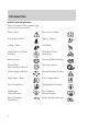
Introduction Vehicle symbol glossary These are some of the symbols you may have on your vehicle.
Introduction Vehicle symbol glossary ', ##% # " # " %! " " " " ## "' " " ## "' !$ % '(% # #' $ " " #' '' %, )# !# " #% $ % & '' %, +$ #& ) & " %" " "' " #%% ' ) " " % ' % ! & #* % ' % " ( ( ! && #" ,&' ! && " % #!$ %'! "' % ' %
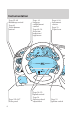
Instrumentation Page 19-20 Headlamp control Page 21 Panel dimmer control Page 21 Luggage compartment control Page 20, 54 Direction indicators/ high beam Page 8-18 Instrument cluster Page 55 Wiper lever Page 56-59 Speed control Page 159-167 Fuse panel 6 Page 54 Steering wheel adjustment Page 53 Ignition switch
Instrumentation Page 32 Hazard flasher Page 73 AntiĆtheft system control light Page 33-53 Electronic sound system Page 24-31 Climate controls Page 32 Rear window defrost control Page 30 Air conditioning/ Recirculated air control 7
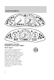
Instrumentation INSTRUMENT CLUSTER WARNING LIGHTS AND CHIMES Check engine Your vehicle is equipped with a computer that monitors the engine's emission control system. This system is commonly known as the On Board Diagnostics System (OBD II). This OBD II system protects the environment by ensuring that your vehicle continues to meet government emission standards. The OBD II system also assists the service technician in properly servicing your vehicle.
Instrumentation The indicator light illuminates when the ignition is first turned to the ON position to check the bulb. If it comes on after the engine is started, one of the engine's emission control systems may be malfunctioning. The light may illuminate without a driveability concern being noted. The vehicle will usually be driveable and will not require towing. What you should do if the check engine light illuminates This means that the OBD II system has detected a malfunction.
Instrumentation If the light remains on, have your vehicle serviced at the first available opportunity. Engine misfire is occurring which could damage your catalytic converter. You should drive in a moderate fashion (avoid heavy acceleration and deceleration) and have your vehicle serviced at the first available opportunity.
Instrumentation Air bag readiness Momentarily illuminates when the ignition is turned on. If the light fails to illuminate, continues to flash or remains on, have the system serviced immediately. Doors ajar Illuminates when the ignition is in the ON or START position and any door or the luggage compartment is open. Turn signal Illuminates when the left or right turn signal or the hazard lights are turned on.
Instrumentation Safety belt " & # " ! % " " ! "# " " ! " " & # " !" & # ! "& "! " " " " Charging system # " ! % " " ! "# " " ! " " ! " ! # " ! % " "" & ! " & # " !&!" ! $ Engine oil pressure # " ! % " !!# ! % " " " $ ! ! ! !
Instrumentation Brake system warning Momentarily illuminates when the ignition is turned to the ON position and the engine is off. If brake warning lamp does not illuminate at this time, seek service immediately. Also illuminates when the parking brake is engaged. Illumination after releasing the parking brake indicates low brake fluid level or ABS (if equipped) failure and the brake system should be serviced immediately.
Instrumentation Speed control (if equipped) Upshift (if equipped) O/D off (if equipped)
Instrumentation Headlamps on warning chime Sounds when the headlamps or parking lamps are on, the ignition is off (and the key is not in the ignition) and the driver's door is opened. Safety belt warning chime Chimes to remind you to fasten your safety belts. For information on the safety belt warning chime, refer to the chapter. Supplemental restraint system (SRS) warning chime For information on the SRS warning chime, refer to the chapter.
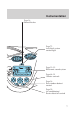
Instrumentation INSTRUMENT CLUSTER GAUGES Temperature gauge
Instrumentation Tachometer (if equipped)
Instrumentation Speedometer Indicates the current vehicle speed. Odometer Registers the total kilometers (miles) of the vehicle. Tripmeter Registers the kilometers (miles) of individual journeys. To reset depress the control. Fuel gauge Displays approximately how much fuel is in the fuel tank (when the key is in the ON position). The fuel gauge may vary slightly when the vehicle is in motion. The ignition should be in the OFF position while the vehicle is being refueled.
Controls and features HEADLAMP CONTROL Fog lights (if equipped)
Controls and features The control light will illuminate when the fog lights are in use. The should be used only when visibility is considerably restricted by fog, snow or rain. Daytime running lights (DRL) (if equipped) Turns the headlamps on. To activate: • The engine must be running and • The headlamp control is in the OFF or parking lamps position. The Daytime Running Light (DRL) system will not illuminate the tail lamps and parking lamps. Turn on your headlamps at dusk.
Controls and features PANEL DIMMER CONTROL This can be adjusted to vary the intensity of the panel lighting. Operates only when the exterior lights are switched on. REMOTE LUGGAGE COMPARTMENT RELEASE (if equipped) To open the luggage compartment, press the control. The control does not function if the vehicle is traveling faster than 7 km/h (4 mph). If the vehicle is equipped with central locks and all the doors are locked, the control does not function.
Controls and features To open the luggage compartment door (lid) from the inside, pull the illuminated T" shaped handle and push open the door (lid). The material the handle is made of will glow in the darkness of the luggage compartment following a brief exposure to ambient light. The T" shaped handle will be located either on the luggage compartment door (lid) or inside the luggage compartment near the tail lamps. Keep vehicle doors and luggage compartment locked and keep keys out of a child's reach.
Controls and features On hot days, the temperature in the trunk can rise very quickly and cause injury or death to any living thing (animal, small child) entrapped in the trunk. Sedans may be equipped with glow in the dark unlocking controls, which allow a means of escape by exiting through the folding rear seatback. These are located near the upper front edge of the decklid opening, on each side of the opening. Pull one or both of the unlocking controls and push the rear seatback forward.
Controls and features CLIMATE CONTROLS Heater only system Fan speed control Temperature control Mode selector control
Controls and features (Panel) Distributes outside air • through the instrument panel registers. • (Panel and Floor) Distributes outside air through the instrument panel registers and the floor ducts. • (Floor) Allows for maximum heating. Distributes outside air through the floor ducts. • ā (Floor and defrost) Distributes outside air through the windshield defroster ducts and the floor ducts. • ā (Defrost) Distributes outside air through the windshield defroster ducts.
Controls and features Operating Tips • In humid weather, select ā (Defrost) before driving. This will help to reduce fogging on your windshield. After a few minutes, select any desired position. • Do not put objects under the front seat that will interfere with airflow to the back seats. • Remove any snow, ice or leaves from the air intake area (at the bottom of the windshield under the hood). • When placing objects on top of your instrument panel, be careful to not place them over the defroster outlets.
Controls and features Manual heating and air conditioning system (if equipped) Fan speed control Temperature control Mode selector control
Controls and features The air conditioning functions in all modes if the outside temperature is 4°C (40°F) or higher. Since the air conditioner removes considerable moisture from the air during operation, it is normal if clear water drips on the ground under the air conditioner drain while the system is working and even after you have stopped the vehicle. • (Panel) Distributes air through the instrument panel registers.
Controls and features • ā (Floor and defrost) Distributes air through the windshield defroster ducts and the floor ducts. Heating and air conditioning capabilities are provided in this mode. For added customer comfort, when the temperature control knob is anywhere in between the full hot and full cold positions, the air distributed through the floor ducts will be slightly warmer than the air sent to the windshield defroster ducts.
Controls and features Air conditioning control (if equipped) Press the control to turn on or off. The control light in the switch indicates operation. This mode can be used for air conditioning. It will only function if the temperature is about 4°C (40°F) or higher. For maximum A/C performance, press both A/C and recirculated air controls. Recirculated air control Press the control to toggle between outside air and recirculated air.
Controls and features • Remove any snow, ice or leaves from the air intake area (at the bottom of the windshield under the hood). • If the vehicle has been parked with the windows closed during hot weather, the air conditioner will do a much faster job of cooling if you drive for two or three minutes with the windows open. This will force most of the hot, stale air out of the vehicle. • When placing objects on top of your instrument panel, be careful to not place them over the defroster outlets.
Controls and features REAR WINDOW DEFROSTER " " " " " " ! $ " $ ! HAZARD FLASHER CONTROL %
Controls and features AUDIO SYSTEM Anti-theft protection panel 2 3
Controls and features Replacement panels Your Ford Dealer will require the following if you need to order a replacement panel: 1. Your name and address. 2. The Vehicle Identification Number (visible on a plate mounted on the instrument panel). Refer to illustration under in the chapter. 3. The audio unit type (e.g., 4500, 4600). 4. Proof of identification (e.g., driver's license, identity card). 5.
Controls and features Radio reception ! ! ! $ % !" ! ! ! ! ! ! # $ ! $ % " ! ! ! % " " % ! AM reception ! ! ! # ! " " !% !! !" $ # ! ! ! ! % ! ! ! ! ! ! FM reception $ # " !% " ! "! ! ! " ! ! !
Controls and features 4100N AUDIO CONTROLS
Controls and features On/Off Volume control Sound adjustments Bass Treble Fade Balance
Controls and features Waveband selector (AM/FM) Press repeatedly during radio reception to select AM, FM1 or FM2. The display indicates the selection made. Seek/tuning control (SEEK) Press A or " to locate the next station down or up the waveband selected. Manual tuning control (TUNE) Press A or " to locate the next frequency step down or up the waveband selected. Station presets Tune to the station required. Press and hold one of the preset buttons. When sound returns, the station has been stored.
Controls and features 4500N AND 4600N AUDIO CONTROLS The 4500 radio/cassette is compatible with a CD changer.
Controls and features The 4600 radio/ CD player is compatible with a CD changer.
Controls and features On/off Press for on/off. This button can also operate the radio for up to one hour with the ignition turned off. The radio automatically switches off after one hour. This function can be used repeatedly. Volume control The display indicates the level selected. Bass/Treble control Press BASS/TREBLE" once for bass or twice for treble and use the volume control for adjustment. The display indicates the level selected.
Controls and features Fade/Balance control Press FADE/BAL" once for fade (front to rear) or twice for balance (left to right), and use the volume control for sound system adjustment. The display indicates the level selected. To adjust beyond the 0" setting, stop rotating the control at 0" then restart. The fade function is applicable to vehicles with front and rear speakers only. Seek tuning control (SEEK) During radio reception, press A or " to locate the next station down or up the waveband selected.
Controls and features Waveband selector (AM/FM) • Press repeatedly during radio reception to select AM, FM1, FM2 or AutoStore (see ). The display indicates the selection made. • Press during tape or CD playback to return to radio reception. AutoStore selector AutoStore selects six strong FM station signals and stores them on the preset buttons. • Press and hold the AM/FM button to activate AutoStore. • AST" flashes in the display while the unit searches through the FM frequencies.
Controls and features Station preset buttons Select a waveband (FM or AM) and tune to the station required. Press and hold one of the preset buttons. When sound returns, the station has been stored. 24 preset frequencies can be stored - six on each of the AM, FM1, FM2 and AutoStore bands. Stereo indicator The symbol shows whenever a stereo signal is received. Clock (CLK) Press CLK to alternate the display between clock and, when playing, CD elapsed time.
Controls and features MENU button (main features) – radio Use the MENU button to access main menu features and the SEEK button for adjustment. Manual tuning Press the MENU button once until a display like the one shown opposite appears. Then use the SEEK button to make manual tuning adjustments. The FM waveband allows 200kHz tuning steps, and the AM band 10kHz steps. Automatic Volume Control (AVC) Press the MENU button twice until a display like the one shown opposite appears.
Controls and features 4500N Units only Tape control buttons Insert a tape and playback will automatically override radio or CD. TAPE A" or TAPE B" appears in the display to indicate which side of the tape is playing. Note that the tape side facing upward in the audio unit is always considered TAPE A". Fast forward/rewind • Press button fully in for fast forward. • Press and release button to end fast forward and restart the tape. • Press button fully in for rewind.
Controls and features Tape side selection During tape playback, press both and buttons partially in to change the tape side being played. Tape eject Press both and buttons fully in to eject the cassette and restore radio reception. To pause tape playback Press AM/FM to pause tape playback and restore radio reception, or the CD button for CD playback. A square in the display indicates there is a tape inserted. To restart tape playback Press both tape buttons partially in or press AMS to resume tape playback.
Controls and features MENU button (main features) – tape Use the MENU button to access main menu features, and the SEEK button for adjustment. Dolby Br noise reduction Press the MENU button repeatedly until a display like the one shown opposite appears. Then use the SEEK button to turn this function on (NR ON") or off (NR OFF"). With the function on, background tape noise is reduced. Automatic Volume Control (AVC) Press the MENU button repeatedly until a display like the one shown opposite appears.
Controls and features 4600N units only CD Playback (8cm and 12cm CDs can be played) CD playback starts and radio reception is interrupted, when a CD is inserted into the entry slot. PLAY CD" appears in the display. Press CD to start playback from a CD already in the audio unit. If no disc is inserted, NO CD" appears in the display. Pressing CLK alternates the display between elapsed track time and clock time. The display indicates elapsed track time up to 19:59.
Controls and features Fast forward/reverse Press and hold A SEEK or SEEK " to search backwards or forwards across the tracks on the disc. Scan mode Press the SCAN button. Each track is played in turn for a short period. During this scan, SCAN" appears in the display. To continue listening to a track, press SCAN. Pressing SCAN at any time will end the scan. To end CD playback Press the AM/FM button to restore radio reception without ejecting the disc.
Controls and features CD care and maintenance For best possible sound quality, use CDs that are clean and in good condition. CD error codes Codes may be shown in the audio unit display that indicate errors with the CD unit. These codes are as follows: Display E11 or E15 Description/rectification Internal fault, see your dealer. E12 Clean the disc and try again. If error still shows, see your dealer. E14 Ambient temperature too hot - unit will not work until it has cooled down.
Controls and features Random track playback (SHUF) Press the MENU button until a display like the one shown opposite appears. Then use the SEEK button to turn this function on (SHUFĆON") or off (SHUFĆOFF"). With the function on, the Cd" indicator is replaced by SHUF" as a new track is selected. Track compression (COMP) Press the MENU button repeatedly until a display like the one shown opposite appears. Then use the SEEK button to turn this function on or off.
Controls and features • When selected, Automatic Volume Control increases or decreases the audio unit's volume level to compensate for engine and road speed noise. • The SEEK button provides a selection of settings between AVC OFF" and AVC +7". The display shows the level selected. This feature is not available on some vehicles and may not appear as a menu function. POSITIONS OF THE IGNITION 1. LOCK, locks the steering wheel, automatic transmission gearshift lever and allows key removal.
Controls and features TILT AND TELESCOPE STEERING (if equipped) " ! TURN SIGNAL CONTROL • •
Controls and features WINDSHIELD WIPER/WASHER CONTROL Mist function Rear window wiper and washer (if equipped)
Controls and features SPEED CONTROL (if equipped) To turn speed control on • Press ON. Vehicle speed cannot be controlled until the vehicle is travelling at or above 48 km/h (30 mph). Do not use the speed control in heavy traffic or on roads that are winding, slippery, or unpaved. Do not shift the gearshift lever into N (Neutral) with the speed control on. To turn speed control off • Press OFF or • turn off the vehicle ignition.
Controls and features To set a speed • Press SET ACC. For speed control to operate, the speed control must be ON and the vehicle speed must be greater than 48 km/h (30 mph). The control light in the instrument panel will illuminate. If you drive up or down a steep hill, your vehicle speed may vary momentarily slower or faster than the set speed. This is normal. Speed control cannot reduce the vehicle speed if it increases above the set speed on a downhill.
Controls and features To set a higher speed • Press and hold SET ACC. Release the control when the desired vehicle speed is reached, or • press and release SET ACC. Each press will increase the set speed by 1.6 km/h (1 mph) or • accelerate with your accelerator pedal. When the desired vehicle speed is reached, press and release SET ACC. You can accelerate with the accelerator pedal at any time during speed control usage.
Controls and features To disengage speed control • Depress the brake pedal or • depress the clutch pedal (if equipped). Disengaging the speed control will not erase the previously programmed set speed. To return to a set speed • Press RES. For RES to operate, the vehicle speed must be faster than 48 km/h (30 mph).
Controls and features DOME LAMPS • • Reading lamps (if equipped)
Controls and features POWER WINDOWS (if equipped) • • One touch down Window lock
Controls and features POWER SIDE VIEW MIRRORS The control can be swiveled and turned. Turn the control counterclockwise to adjust the driver's side mirror, clockwise to adjust the passenger's side mirror. Adjust the selected mirror by moving the center control in the desired direction. Then turn the control back to the center position. CHILDPROOF REAR DOOR LOCKS When these locks are set, the rear doors cannot be opened from inside. The rear doors can be opened from the outside when the doors are unlocked.
Controls and features LUGGAGE COVER Coupe Detach the lifting straps on the liftgate. Release the cover at the sides and pull it out horizontally without tilting it. Replace in reverse order. Make sure the cover is properly aligned when inserting it. Wagon Pull out the roller cover and secure the retaining points. The cover can be removed completely by pressing inward on both ends of the support.
Controls and features POSITIVE RETENTION FLOOR MAT (if equipped) Position the floor mat so that the eyelet is over the pointed end of the retention post and rotate forward to lock in. Make sure that the mat does not interfere with the operation of the accelerator or the break pedal. To remove the floor mat, reverse the installation procedure. REMOTE ENTRY SYSTEM (if equipped) Your vehicle is equipped with a remote entry system which allows you to: • unlock the vehicle doors without a key.
Controls and features Unlocking the doors " Locking the doors ! ! "
Controls and features Opening the luggage compartment Press the control once or twice (depending on when the vehicle was built) to open the luggage compartment. Be certain the luggage compartment is closed before driving your vehicle. The luggage compartment may appear closed, but it may not be latched. Failure to do so may cause objects to fall out of the luggage compartment or block rear view vision. Sounding a panic alarm Press this control to turn on the alarm.
Controls and features Illuminated entry The interior lamps will illuminate when the remote entry system is used to unlock the door(s). The illuminated entry system will automatically turn off the interior lights if the ignition switch is turned to the RUN position, or if the remote transmitter lock control is pressed, or after 20 seconds of illumination if all doors are closed. Note that the illuminated entry system will not function if the dome lamp switch is in the OFF position.
Controls and features 2. Place the positive (+) side of new battery in the same orientation. Refer to the diagram inside the transmitter unit. 3. Snap the two halves back together. Replacement of the battery will cause the remote transmitter to become deprogrammed from your vehicle. The remote transmitter should operate normally after battery replacement.
Controls and features 2. Turn the ignition lock from OFF (2) to ON (3) at least 4 times in 6 seconds. 3. Switch off the ignition. Now the control module has entered the learning mode" for 10 seconds. This mode is indicated by a chime. 4. While the control module is in the learning mode", press and hold one of the buttons of the remote transmitter until a chime sounds. This indicates a new transmitter code has been successfully received.
Controls and features PERIMETER ALARM SYSTEM (if equipped) " " (" " !&!" % $ " & # $ # #" ' " & Arming the system " " % " " & # $ # #" ' " & # #" ' " & # ! " !&!" % ! " ' ! ! % ! # " !&!" ! & " % $ " & ! #" " & " % " ! % " !&!" • !! " " " ! "" " •
Controls and features SECURILOCKT PASSIVE ANTI-THEFT SYSTEM Your vehicle is equipped with a codedĆkey antiĆtheft system. Only the correct key will be able to start your vehicle. If your keys are lost or stolen, you must take your vehicle to your dealership for key reprogramming. The SecuriLockT passive antiĆtheft system provides an advanced level of vehicle theft protection. Your vehicle's engine can only be started with the two special SecuriLockT electronically coded keys provided with your vehicle.
Controls and features The SecuriLockT passive antiĆtheft system is not compatible with aftermarket remote start systems. Use of these systems may result in vehicle starting problems and a loss of security protection. Large metallic objects or devices such as the Mobil SpeedpassT on the same key ring as your SecuriLockT key may cause vehicle starting problems.
Controls and features Theft indicator When the ignition is turned to ON or START, the theft indicator on the instrument panel will light for three seconds and then go out (indicates proper SecuriLockT system operation). If the key is in the ignition and the theft indicator stays on for an extended period of time or flashes rapidly, have the system serviced by your dealership or a qualified technician.
Controls and features Procedure to program spare SecuriLockT keys New SecuriLockT keys must have the correct mechanical key cut for your vehicle. Conventional (non SecuriLockT) keys be programmed to your vehicle. The correct type of SecuriLockT key for your vehicle is identifiable by the alphanumeric characters stamped on the key blade.
Controls and features 1. Insert the first previously programmed SecuriLockT key into the ignition and turn the ignition from OFF (2) to ON (3) (maintain ignition in ON for at least one second). 2. Turn ignition to OFF and remove the first SecuriLockT key from the ignition. 3.
Controls and features If the programming procedure was successful, the new SecuriLockT key(s) will start the vehicle's engine. The theft indicator (located on the instrument panel) will light for three seconds and then go out. If the programming procedure was not successful, the new SecuriLockT key(s) will not operate the vehicle's engine. The theft indicator will flash on and off. Wait at least one minute and then repeat the procedure from step 1.
Seating and safety restraints SEATING Never adjust the driver's seat or seatback when the vehicle is moving. Adjustable head restraints Your vehicle is equipped with head restraints which are vertically adjustable. The purpose of these head restraints is to limit head motion in the event of a rear collision. To properly adjust your head restraints, lift the head restraint so that it is located directly behind your head or as close to that position as possible.
Seating and safety restraints Turn the handle to adjust the height of the seat. Lift the control to adjust the angle of the seatback. Folding the seat forward (Coupe) Pull the control and fold the seatback forward. Fold back the seatback until it locks with a distinct click". Rock the seat to ensure that the catch is securely engaged. Do not place any objects behind the seat which could prevent the engagement of the seat lock.
Seating and safety restraints Folding the rear seat cushion forward Folding the rear seatback forward Coupe and wagon Sedan
Seating and safety restraints Returning the rear seatback to an upright position Fold back the seatback until it locks with a distinct click". Do not place any objects behind the seat which could prevent the seat from locking. Make sure the safety restraints will function properly and are positioned in front of the seatback. Note that the center rear seat belt cannot be pulled out until the seatback has latched completely.
Seating and safety restraints SAFETY RESTRAINTS Safety restraints precautions ! " ! " ! " ! " " ! " " ! " ! "
Seating and safety restraints It is extremely dangerous to ride in a cargo area, inside or outside of a vehicle. In a collision, people riding in these areas are more likely to be seriously injured or killed. Do not allow people to ride in any area of your vehicle that is not equipped with seats and safety belts. Be sure everyone in your vehicle is in a seat and using a safety belt properly.
Seating and safety restraints ! ! ! Energy Management Feature ! ! ! !
Seating and safety restraints BELT AND RETRACTOR ASSEMBLY MUST BE REPLACED if the seat belt assembly automatic locking retractor feature or any other seat belt function is not operating properly when checked according to the procedures in Workshop Manual. Failure to replace the Belt and Retractor assembly could increase the risk of injury in collisions.
Seating and safety restraints Safety belt pretensioner Your vehicle is equipped with safety belt pretensioners at the driver and front passenger seating positions. The safety belt pretensioner is a device which removes excess webbing from the safety belt system. The safety belt pretensioner uses the same crash sensor system as the front air bag supplemental restraint system (SRS). When the safety belt pretensioner deploys, webbing from the lap and shoulder belt is tightened.
Seating and safety restraints When to use the automatic locking mode • When a tight lap/shoulder fit is desired. • a child safety seat is installed in a passenger front or outboard rear seating position (if equipped). Refer to or later in this chapter. Always transport children 12 years old and under in the back seat and always use appropriate child restraints. How to use the automatic locking mode • Buckle the combination lap and shoulder belt.
Seating and safety restraints Front safety belt height adjustment ! ! !
Seating and safety restraints Safety belt warning light and warning chime Conditions of operation If... Then...
Seating and safety restraints Belt Minder (if equipped) The Belt Minder feature is a supplemental warning to the safety belt warning function. This feature provides additional reminders to the driver that the driver's safety belt is unbuckled by intermittently sounding a chime and illuminating the warning light in the instrument cluster. If... Then... If the driver's safety belt is not buckled approximately 5 seconds after the safety belt warning light has turned off ...
Seating and safety restraints The purpose of the Belt Minder is to remind occasional wearers to wear safety belts all of the time. The following are reasons most often given for not wearing safety belts: (All statistics based on U.S. data) Reasons given... Consider... Crashes are rare events" 36 700 crashes occur every day. The more we drive, the more we are exposed to rare" events, even for good drivers. 1 in 4 of us will be seriously injured in a crash during our lifetimes.
Seating and safety restraints Reasons given... Consider... Belts wrinkle my clothes" Possibly, but a serious crash can do much more than wrinkle your clothes, particularly if you are unbelted. The people I'm with don't wear belts" Set the example, teen deaths occur 4 times more often in vehicles with TWO or MORE people. Children and younger brothers/sisters imitate behavior they see. I have an air bag" Air bags offer greater protection when used with safety belts.
Seating and safety restraints Do not sit on top of a buckled safety belt to avoid the Belt Minder chime. Sitting on the safety belt will increase the risk of injury in an accident. To disable (one time) or deactivate the Belt Minder feature please follow the directions stated below. One time disable Any time the safety belt is buckled and then unbuckled during an ignition ON cycle, Belt Minder will be disabled for that ignition cycle only.
Seating and safety restraints • the driver's safety belt is unbuckled. • the parklamps/headlamps are in OFF position. To reduce the risk of injury, do not deactivate/activate the Belt Minder feature while driving the vehicle. 1. Turn the ignition switch to the ON position (DO NOT START THE ENGINE). 2. Wait until the warning light turns off (approximately 1Ć2 minutes). • Steps 3-5 must be completed within 60 seconds or the procedure will have to be repeated. 3.
Seating and safety restraints 6. Within seven seconds of the warning light turning off, buckle then unbuckle the safety belt. • This will disable Belt Minder if it is currently enabled, or enable Belt Minder if it is currently disabled. 7. Confirmation of disabling Belt Minder is provided by flashing the light four times per second for three seconds. 8.
Seating and safety restraints Safety belt extension assembly If the safety belt is too short, even when fully extended, 20 cm (8 inches) can be added to the safety belt assembly by adding a safety belt extension assembly (part number 611C22). Safety belt extension assemblies can be obtained from your dealer at no cost. Use only extensions manufactured by the same supplier as the safety belt. Manufacturer identification is located at the end of the webbing on the label.
Seating and safety restraints Safety belt maintenance Inspect the safety belt systems periodically to make sure they work properly and are not damaged. Inspect the safety belts to make sure there are no nicks, wears or cuts, replacing if necessary. All safety belt assemblies (slide bar) (if equipped), shoulder belt height adjusters (if equipped), child safety seat tether bracket assemblies (if equipped), and attaching hardware, should be inspected after a collision.
Seating and safety restraints AIR BAG SUPPLEMENTAL RESTRAINT SYSTEM (SRS) Important supplemental restraint system (SRS) precautions The supplemental restraint system is designed to work with the safety belt to help protect the driver and right front passenger from certain upper body injuries. Air bags DO NOT inflate slowly or gently and the risk of injury from a deploying air bag is the greatest close to the trim covering the air bag module.
Seating and safety restraints NHTSA recommends a minimum distance of at least 25 cm (ten [10] inches) between an occupant's chest and the air bag module. Steps you can take to properly position yourself away from the air bag: • Move your seat to the rear as far as you can while still reaching the pedals comfortably. • Recline your seat slightly (one or two degrees) from the upright position. Do not put anything on or over the air bag module.
Seating and safety restraints Children and air bags For additional important safety information, read all information on safety restraints in this guide. Children must always be properly restrained. Accident statistics suggest that children are safer when properly restrained in the rear seating positions than in the front seating positions. Failure to follow these instructions may increase the risk of injury in a collision. Air bags can kill or injure a child in a child seat.
Seating and safety restraints The fact that the air bags did not inflate in a collision does not mean that something is wrong with the system. Rather, it means the forces were not of the type sufficient to cause activation. The front air bags are designed to inflate in frontal and nearĆfrontal collisions, not rollover, sideĆimpact, or rear impacts. For information on sideĆimpact collisions, refer to in this chapter. The air bags inflate and deflate rapidly upon activation.
Seating and safety restraints While the system is designed to help reduce serious injuries, it may also cause minor burns, abrasions, swelling or temporary hearing loss. Because air bags must inflate rapidly and with considerable force, there is the risk of death or serious injuries such as fractures, facial and eye injuries or internal injuries, particularly to occupants who are not properly restrained or are otherwise out of position at the time of air bag deployment.
Seating and safety restraints The SRS consists of: • driver and passenger air bag modules (which include the inflators and air bags). • side air bags (if equipped). Refer to later in this chapter. • one or more impact and safing sensors. • a readiness light and tone. • and the electrical wiring which connects the components.
Seating and safety restraints A difficulty with the system is indicated by one or more of the following: • The readiness light will either flash or stay lit. • The readiness light will not illuminate immediately after ignition is turned on. • A series of five beeps will be heard. The tone pattern will repeat periodically until the program and light are repaired. If any of these things happen, even intermittently, have the SRS serviced at your dealership or by a qualified technician immediately.
Seating and safety restraints Do not attempt to service, repair, or modify the air bag Supplemental Restraint System or its fuses. See your Ford or LincolnĆMercury dealer. All occupants of the vehicle including the driver should always wear their safety belts even when an air bag SRS is provided.
Seating and safety restraints The side air bags are fitted on the outboard side of the seatbacks of the front seats. In certain lateral collisions, the air bag on the side affected by the collision will be inflated, even if the respective seat is not occupied. The air bag was designed to inflate between the door panel and occupant to further enhance the protection provided occupants in side impact collisions.
Seating and safety restraints If the side air bag has deployed, the air bag will not function again. The side air bag system (including the seat) must be inspected and serviced by a qualified technician in accordance with the vehicle service manual. If the air bag is not replaced, the unrepaired area will increase the risk of injury in a collision. Determining if the system is operational The SRS uses a readiness light in the instrument cluster or a tone to indicate the condition of the system.
Seating and safety restraints If either of these indications occurs, even intermittently, have the SRS serviced at your dealership or by a qualified technician immediately. Unless serviced, the system may not function properly in the event of a collision. Disposal of air bags and air bag equipped vehicles For disposal of air bags or air bag equipped vehicles, see your local dealership or a qualified technician. Air bags MUST BE disposed of by qualified personnel.
Seating and safety restraints Important child restraint precautions You are required by law to use safety restraints for children in the U.S. and Canada. If small children ride in your vehicle (generally children who are four years old or younger and who weigh 18 kg [40 lbs] or less), you must put them in safety seats made especially for children. Check your local and state or provincial laws for specific requirements regarding the safety of children in your vehicle.
Seating and safety restraints Children and safety belts If the child is the proper size, restrain the child in a safety seat. Children who are too large for child safety seats (as specified by the child safety seat manufacturer) should always wear safety belts. Follow all the important safety restraints and air bag precautions that apply to adult passengers in your vehicle.
Seating and safety restraints To improve the fit of lap and shoulder belts on children who have outgrown child safety seats, Ford recommends use of a beltĆpositioning booster seat that is labelled as conforming to all Federal motor vehicle safety standards. BeltĆpositioning booster seats raise the child and provide a shorter, firmer seating cushion that encourages safer seating posture and better fit of lap and shoulder belts on the child.
Seating and safety restraints SAFETY BELTS FOR CHILDREN Child and infant or child safety seats $ % # ! $ # ! ! ! # $ $ ! ! $ ! " $ ! ! $ $ $ ! ! $ • " # #
Seating and safety restraints • Place seatback in upright position. • Put the safety belt in the automatic locking mode. Refer to (passenger side front and outboard rear seating positions) (if equipped). Ford recommends the use of a child safety seat having a top tether strap. Install the child safety seat in a seating position which is capable of providing a tether anchorage. For more information on top tether straps see in this chapter.
Seating and safety restraints Installing child safety seats in combination lap and shoulder belt seat positions ! " ! " ! "
Seating and safety restraints 3. While holding the shoulder and lap belt portions together, route the tongue through the child seat according to the child seat manufacturer's instructions. Be sure the belt webbing is not twisted. 4. Insert the belt tongue into the proper buckle (the buckle closest to the direction the tongue is coming from) for that seating position until you hear and feel the latch engage. Make sure the tongue is latched securely by pulling on it. 5.
Seating and safety restraints 6. Allow the belt to retract. The belt will click as it retracts to indicate it is in the automatic locking mode. 7. Pull the lap belt portion across the child seat toward the buckle and pull up on the shoulder belt while pushing down with your knee on the child seat. 8. Allow the safety belt to retract to remove any slack in the belt. 9. Before placing the child in the seat, forcibly tilt the seat forward and back to make sure the seat is securely held in place. 10.
Seating and safety restraints Attaching child safety seats with ISOFIX attachments Some child seat manufacturers make safety seats that are labeled as ISOFIX or ISOFIXĆcompatible child seats. These seats include two rigid or webbing mounted attachments that connect to two ISOFIX anchors at specific seating positions in your vehicle. This type of child seat eliminates the need to use seat belts to attach the child seat.
Seating and safety restraints The ISOFIX anchors are located on the rear section of the seat cushion, and at the bottom of the seatback. Follow the child seat manufacturer's instructions to properly install safety seats with ISOFIX or ISOFIXĆcompatible attachments. Attach the ISOFIX or ISOFIXĆcompatible child seat only to the appropriate locations shown. Once you have installed the ISOFIX safety seat, assure that the seat is properly attached to the ISOFIX and tether anchors.
Seating and safety restraints Attaching child safety seats with tether straps Most new forwardĆfacing child safety seats include a tether strap which goes over the back of the seat and hooks to an anchoring point. Tether straps are available as an accessory for many older safety seats. Contact the manufacturer of your child safety seat for information about ordering a tether strap. The rear seats of your vehicle are equipped with builtĆin tether strap anchors located behind the seats as described below.
Seating and safety restraints ! $ " ! " $ ! " # $ $ " " $ ! ! " $ " # ! ! ! # # !
Seating and safety restraints 5. Clip the tether strap to the anchor as shown. If the tether strap is clipped incorrectly, the child safety seat may not be retained properly in the event of a collision. 6. Refer to the section of this chapter for further instructions to secure the child safety seat. 7. Tighten the child safety seat tether strap according to the manufacturer's instructions.
Starting PREPARING TO START YOUR VEHICLE ! ! ! & ! ! & ! & ! ! ! ' " " ! ! " ! " ! ! " ! ! ! ! ! " ' ! # ! ! " ! ! & " ! ! $ & " # " !& ! ! ! ! ! ! ! # ! ! ! 1 %! !
Starting Do not start your vehicle in a closed garage or in other enclosed areas. Exhaust fumes can be toxic. Always open the garage door before you start the engine. See in this chapter for more instructions. If you smell exhaust fumes inside your vehicle, have your dealer inspect your vehicle immediately. Do not drive if you smell exhaust fumes. Important safety precautions A computer system controls the engine's idle revolutions per minute (RPM).
Starting Before starting the vehicle: 1. Make sure all vehicle occupants have buckled their safety belts. For more information on safety belts and their proper usage, refer to the chapter. 2. Make sure the headlamps and vehicle accessories are off. If starting a vehicle with an automatic transaxle: • Make sure the parking brake is set. • Make sure the gearshift is in P (Park). If starting a vehicle with a manual transaxle: • Make sure the parking brake is set.
Starting Make sure the corresponding lights (if equipped) illuminate briefly. If a light fails to illuminate, have the vehicle serviced. • If the driver's safety belt is fastened the light will not illuminate. STARTING THE ENGINE 1. Turn the key to 4 (START) without pressing the accelerator pedal and release as soon as the engine starts. The key will return to 3 (ON).
Starting 2. If the temperature is above -12ºC (10ºF) and the engine does not start within five seconds on the first try, turn the key to OFF, wait ten seconds and try again. 3. If the temperature is below -12ºC (10ºF) and the engine does not start in fifteen seconds on the first try, turn the key to OFF and wait ten seconds and try again. If the engine does not start in two attempts, depress the accelerator and start the engine while holding the accelerator down to the floor.
Starting To prevent electrical shock, do not use your heater with ungrounded electrical systems or twoĆpronged (cheater) adapters. Guarding against exhaust fumes Although odorless and colorless, carbon monoxide is present in exhaust fumes. Take precautions to avoid its dangerous effects. If you ever smell exhaust fumes of any kind inside your vehicle, have your dealer inspect and fix your vehicle immediately. Do not drive if you smell exhaust fumes. These fumes are harmful and could kill you.
Starting Engine exhaust, some of its constituents, and certain vehicle components contain or emit chemicals known to the State of California to cause cancer, and birth defects or other reproductive harm. Important ventilating information If the engine is idling while the vehicle is stopped in an open area for long periods of time, open the windows at least 2.5 cm (one inch). Adjust the heating or air conditioning (if equipped) to bring in fresh air.
Driving BRAKES Your service brakes are selfĆadjusting. Refer to the Scheduled Maintenance Guide" for scheduled maintenance. Occasional brake noise is normal and often does not indicate a performance concern with the vehicle's brake system. In normal operation, automotive brake systems may emit occasional or intermittent squeal or groan noises when the brakes are applied.
Driving Anti-lock brake system (ABS) (if equipped) On vehicles equipped with an antiĆlock braking system (ABS), a noise from the hydraulic pump motor and pulsation in the pedal may be observed during ABS braking events. Rapid pedal pulsation coupled with noise while braking under panic conditions or on loose gravel, bumps, wet or snowy roads is normal and indicates proper functioning of the vehicle's antiĆlock brake system.
Driving ABS warning lamp (if equipped) The warning lamp in the instrument cluster momentarily illuminates when the ignition is turned on and the engine is off. If the light does not illuminate momentarily at start up, remains on or continues to flash, the ABS needs to be serviced. With the ABS light on, the antiĆlock brake system is disabled and normal braking is still effective unless the warning light also remains illuminated with parking brake released.
Driving Using ABS (if equipped) • % # $ ! % ! % ! ! ! # " % ! # % ! ! % ! " " ! # % ! " " • ' % % % # % ! # % " ! # % ! "
Driving Parking brake Apply the parking brake whenever the vehicle is parked. To set the parking brake, pull the handle up as far as possible. The warning lamp in the instrument cluster illuminates and remains illuminated (when the ignition is turned ON) until the parking brake is released. The parking brake is not recommended to stop a moving vehicle. However, if the normal brakes fail, the parking brake can be used to stop your vehicle in an emergency.
Driving Push the button on the end of the parking brake and push the handle down as fas as possible to release the brake. Driving with the parking brake on will cause the brakes to wear out quickly and reduce fuel economy. STEERING Your vehicle is equipped with power steering. Power steering uses energy from the engine to help steer the vehicle.
Driving If the steering wanders or pulls, the condition could be caused by any of the following: • underinflated tire(s) on any wheel(s) • high crosswinds • wheels out of alignment • loose or worn components in steering linkage. AUTOMATIC TRANSAXLE OPERATION (if equipped) Brake-shift interlock This vehicle is equipped with a brakeĆshift interlock feature that prevents the gearshift from being moved from P (Park) unless the brake pedal is depressed.
Driving If it is necessary to use the above procedure to move the gearshift, it is possible that a fuse has blown or the vehicle's brakelamps are not operating properly. Refer to in the chapter. Do not drive your vehicle until you verify that the brakelamps are working. If your vehicle gets stuck in mud or snow it may be rocked out by shifting between forward and reverse gears, stopping between shifts, in a steady pattern. Press lightly on the accelerator in each gear.
Driving Driving with automatic transaxle (if equipped) Understanding gearshift positions Depress the locking button and move the automatic gearshift to the desired position. Hold the brake pedal down while you move the gearshift lever from P (Park) to another position. If you do not hold the brake pedal down, your vehicle may move unexpectedly and injure someone. P (Park) Always come to a complete stop before shifting into P (Park). Make sure the gearshift is securely latched in P (Park).
Driving Never leave your vehicle unattended while it is running. R (Reverse) With the gearshift in R (Reverse), the vehicle will move backward. Always come to a complete stop before shifting into and out of R (Reverse) N (Neutral) With the gearshift in N (Neutral), the vehicle can be started and is free to roll. Hold the brake pedal down while in this gear.
Driving D (Overdrive) The normal driving position for the best fuel economy. Transaxle operates in gears One through Four. D (Overdrive) can be deactivated by pressing the transaxle control switch on the gearshift lever. The O/D OFF light will illuminate on the instrument cluster. Engine braking is provided in gears 2, 3, and 4. D (Drive) Transaxle operates in gears One through Three. Activate by pressing the transaxle control switch on the gearshift lever.
Driving To return to D (Overdrive) mode, press the transaxle control switch and the O/D OFF light will no longer be illuminated. Each time the vehicle is started, the transaxle will automatically return to normal overdrive mode. 2 (Second) Use 2 (Second) to startĆup on slippery roads or to provide additional engine braking on downgrades. Upshifts can be made by shifting to D (Drive) or D (Overdrive).
Driving Manual transaxle operation (if equipped) Using the clutch Vehicles equipped with a manual transaxle have a starter interlock that prevents cranking the engine unless the clutch pedal is fully depressed. When starting a vehicle with a manual transaxle, you must: 1. Put gearshift in N (Neutral). 2. Hold down brake pedal. 3. Depress clutch pedal. 4. Turn ignition to position 4 (START) to start the engine, let the engine idle for a few seconds, then shift into gear. 5. Release the brake pedal. 6.
Driving Do not drive with your foot resting on the clutch pedal and do not use the clutch to hold your vehicle at a standstill while waiting on a hill. These actions will seriously reduce clutch life.
Driving Parking your vehicle 1. Apply brake and shift into N (Neutral). 2. Set parking brake. 3. Shift into 1 (First). 4. Turn ignition to position 2 (OFF). Do not park your vehicle in Neutral, it may move unexpectedly and injure someone. Use 1 (First) gear and set the parking brake fully. Reverse Make sure that your vehicle is at a complete stop before you shift into R (Reverse). Failure to do so may damage the transaxle.
Driving • Type A transaxle (with SPI engine) You shift into R (Reverse) only by moving the gearshift fully to the right against a spring pressure and then rearward into R (Reverse) gear. • Type B transaxle (with Zetec engine) To select reverse gear, lift the locking ring (1) and then move the gearshift fully to the right and rearward into R (Reverse) gear (2). Removing key from ignition • Turn the ignition key to position 1. • Remove the ignition key.
Driving VEHICLE LOADING Before loading your vehicle, familiarize yourself with these terms. • Base curb weight: Weight of the vehicle including any standard equipment, fluids, lubricants, etc. It does not include passengers or aftermarket equipment. • Payload: Combined maximum allowable weight of cargo, passengers and optional equipment. The payload equals the gross vehicle weight rating minus base curb weight. • GVW (Gross Vehicle Weight): Base curb weight plus payload weight.
Driving • GAWR (Gross Axle Weight Rating): Carrying capacity for each axle system. The GAWR is specific to each vehicle and is listed on the Safety Compliance Certification Label on the driver's door pillar. • GCWR (Gross Combined Weight Rating): Maximum combined weight of towing vehicle (including passengers and cargo) and the trailer. The GCWR indicates the maximum loaded weight that the vehicle is designed to tow.
Driving • Trailer Weight Range: Specified weight range that the trailer must fall within that ranges from zero to the maximum trailer weight rating. Remember to figure in the tongue load of your loaded trailer when figuring the total weight. Do not exceed the GVWR or the GAWR specified on the Safety Compliance Certification Label. Do not use replacement tires with lower load carrying capacities than the originals because they may lower the vehicle's GVWR and GAWR limitations.
Driving If you are adding weight to the front of your vehicle (potentially including weight added to the cab), the weight added should not exceed the Front Axle Reserve Capacity (FARC). Additional frontal weight may be added to the front axle reserve capacity provided you limit your payload in other ways (i. e. restrict the number of passengers or amount of cargo carried).
Driving TRAILER TOWING Your vehicle is classified as a light duty towing vehicle. Refer to the following chart for towing limits: Towing class Light duty Maximum gross trailer weight 454 kg (1 000 lbs.)* Maximum tongue load 45 kg (100 lbs.) Engine All Hitch design Appropriate aftermarket hitch * Vehicle speed should not exceed 72 km/h (45 mph) when towing on grades. Limit maximum gross trailer weight to 454 kg (1 000 lbs.) and maximum tongue load to 45 kg (100 lbs.
Driving Your vehicle does not come from the factory fully equipped to tow. However, you can contact your local Ford dealer to get the proper towing equipment. Do not tow a trailer until your vehicle has been driven at least 3 000 km (2 000 miles). Towing a trailer places an additional load on your vehicle's engine, transaxle, brakes, tires and suspension. Inspect these components carefully after towing. tire.
Driving Preparing to tow Use the proper equipment for towing a trailer, and make sure it is properly attached to your vehicle. See your dealer or a reliable trailer dealer if you require assistance. Hitches Do not use hitches that clamp onto the vehicle bumper. Use a load carrying hitch. You must distribute the load in your trailer so that 10 - 15% of the total weight of the trailer is on the tongue. Safety chains Always connect the trailer's safety chains to the vehicle.
Driving Do not connect a trailer's hydraulic brake system directly to your vehicle's brake system. Your vehicle may not have enough braking power and your chances of having a collision greatly increase. The braking system of the tow vehicle is rated for operation at the GVWR not GCWR. Trailer lamps Do not connect a trailer's lighting system directly to your vehicle's lighting system. To get the proper equipment for hooking up your trailer's lamps, see your Ford dealer.
Driving When towing a trailer: • Shift out of D (Overdrive) and into 2 (Second) or a lower gear when towing up or down steep hills. This will eliminate excessive downshifting and upshifting for optimum fuel economy and transaxle cooling. • Anticipate stops and brake gradually. Servicing after towing If you tow a trailer for long distances, your vehicle will require more frequent service intervals. Refer to your Scheduled Maintenance Guide" for more information.
Driving • Allow more distance for stopping with a trailer attached. • The trailer tongue weight should be 10-15% of the loaded trailer weight. • After you have traveled 80 km (50 miles), thoroughly check your hitch, electrical connections and trailer wheel lug nuts. • When stopped in traffic for long periods of time in hot weather, place the gearshift in P (Park) and increase idle speed. This aids engine cooling and air conditioner efficiency. • Vehicles with trailers should not be parked on a grade.
Driving Recreational towing Follow these guidelines for your specific powertrain combination to tow your vehicle with all four wheels on the ground (such as behind a recreational vehicle). These guidelines are designed to ensure that your transmission is not damaged due to insufficient lubrication. All Front Wheel Drive (FWD) vehicles An example of recreational towing is towing your vehicle behind a Motorhome.
Driving LUGGAGE RACK (if equipped) The maximum load is 100 kg (220 lb) on the luggage rack structure. The load be placed directly on the luggage rack. The vehicle's roof panel designed to carry a load. When loading the luggage rack, it is recommended to evenly distribute the load, as well as maintain a low center of gravity. Ensure that the load is securely fastened. Driving with items on the luggage rack will result in a deterioration in fuel economy.
Driving DRIVING THROUGH WATER Do not drive quickly through standing water, especially if the depth is unknown. Traction or brake capability may be limited and if the ignition system gets wet, your engine may stall. Water may also enter your engine's air intake and severely damage your engine. If driving through deep or standing water is unavoidable, proceed very slowly. Never drive through water that is higher than the bottom of the hubs. Once through the water, always try the brakes.
Roadside emergencies HAZARD LIGHTS CONTROL Use only in an emergency to warn traffic of vehicle breakdown, approaching danger, etc. The hazard flashers can be operated when the ignition is on or off. • The hazard lights control is located on the instrument panel. • Depress hazard lights control to activate all hazard flashers simultaneously. • Depress control again to turn the flashers off.
Roadside emergencies FUEL PUMP SHUT-OFF SWITCH After a collision, if the engine cranks but does not start, the fuel pump shutĆoff switch may have been activated. The shutĆoff switch is a device intended to stop the electric fuel pump when your vehicle has been involved in a substantial jolt. 1. Turn the ignition to the OFF position. 2. Check the fuel system for leaks. 3.
Roadside emergencies FUSES AND RELAYS Fuses If electrical components in the vehicle are not working, a fuse may have blown. Blown fuses are identified by a broken wire within the fuse. Check the appropriate fuses before replacing any electrical components. Always replace a fuse with one that has the specified amperage rating. Using a fuse with a higher amperage rating can cause severe wire damage and could start a fire.
Roadside emergencies Standard fuse amperage rating and color Color Fuse rating Mini fuses Standard fuses Maxi fuses Fuse link cartridge 2A 3A 4A 5A 7.
Roadside emergencies
Roadside emergencies Passenger compartment fuse panel Fuse 30 31 32 33 34 35 36 37 38 39 40 41 42 43 44 45 46 47 48 49 50 162 Fuse amp. rating 7.5 15 10 15 20 7.5 7.5 10 15 20 15 7.5 7.5 25 7.
Roadside emergencies Passenger compartment fuse panel Fuse 51 52 53 54 55 56 57 58 59 60 61 62 63 Fuse amp. rating 10 15 20 25 25 7.5 7.5 7.5 7.
Roadside emergencies Power distribution box The power distribution box is located in the engine compartment. The power distribution box contains highĆcurrent fuses that protect your vehicle's main electrical systems from overloads. Always disconnect the battery before servicing high current fuses. Always replace the cover to the Power Distribution Box before reconnecting the battery or refilling fluid reservoirs.
Roadside emergencies
Roadside emergencies Power distribution box Fuse 1 2 3 4 5 6 7 8 9 10 11 12 13 14 15 16 17 18 19 20 21 22 23 24 25 26 27 28 29 64 65 166 Fuse amp.
Roadside emergencies Relays in the power distribution box Relay 1 2 3 4 5 6 7 8 9 10 11 12 13 14 15 16 Description Ignition Not used Not used Not used High beams Low beams Fuel pump Engine management Not used Not used Air conditioning Daytime running lights Fog lamps Not used Engine cooling fan level 2 (A/C) Engine cooling fan level 1 167
Roadside emergencies CHANGING THE TIRES If you get a flat tire while driving, do not apply the brake heavily. Instead, gradually decrease your speed. Hold the steering wheel firmly and slowly move to a safe place on the side of the road. The temporary spare tire Your vehicle has a temporary spare tire. The temporary spare tire for your vehicle is labeled as such. It is smaller than a regular tire and is designed for emergency use only. Replace this tire with a fullĆsize tire as soon as possible.
Roadside emergencies When driving with a temporary spare tire : • exceed the maximum speed of 80 km/h (50 mph) under any circumstances • load the vehicle beyond maximum vehicle load rating listed on the Safety Compliance Label • tow a trailer • drive through an automatic car wash, because of the vehicle's reduced ground clearance • try to repair the temporary spare tire or remove it from its wheel • drive for long distances when the temporaryĆuse spare is on • operate the vehicle with more than one te
Roadside emergencies Tire change procedure To prevent the vehicle from moving when you change a tire, be sure the parking brake is set, then block (in both directions) the wheel that is diagonally opposite (other side and end of the vehicle) to the tire being changed. If the vehicle slips off the jack, you or someone else could be seriously injured. 1. Park on a level surface, activate hazard flashers and set parking brake. 2.
Roadside emergencies 3. Remove the spare tire by loosening the tie down bolt in a counterclockwise direction. Take note of the jack position before removal in order to assist in restowing when finished. The jack can be removed by loosening the jack tie down bolt in the counterclockwise direction. The lug wrench is located under the spare tire (Sedan and Coupe) and on the underside of the access cover on Wagons.
Roadside emergencies 4. Remove the center cap or wheel cover. Loosen each wheel lug nut oneĆhalf turn counterclockwise but do not remove them until the wheel is raised off the ground. 5. The vehicle jacking points are depicted on the yellow warning label on the jack shown here. Locate the jack at the half moon cutout located - approximately 15 cm (6 inches) from the front wheel opening (1). - approximately 38 cm (15 inches) from the rear wheel opening (2).
Roadside emergencies ! ! ! ! ! ! ! !
Roadside emergencies 6. Remove the lug nuts with the lug wrench. 7. Replace the flat tire with the spare tire, making sure the valve stem is facing outward. Reinstall lug nuts until the wheel is snug against the hub. Do not fully tighten the lug nuts until the wheel has been lowered. When using a temporary tire, the lug nut washers will not appear to be flush with the rim. This is normal when using the temporary spare tire only. 8. Lower the wheel by turning the jack handle counterclockwise. 9.
Roadside emergencies JUMP STARTING YOUR VEHICLE The gases around the battery can explode if exposed to flames, sparks, or lit cigarettes. An explosion could result in injury or vehicle damage. Do not push start your vehicle. You could damage the catalytic converter. Batteries contain sulfuric acid which burns skin, eyes, and clothing, if contacted. Do not attempt to push start your vehicle. Automatic transaxles do not have pushĆstart capability. Preparing your vehicle 1.
Roadside emergencies 3. Park the booster vehicle close to the hood of your disabled vehicle, making sure the two vehicles touch. Set the parking brake on both vehicles and stay clear of the engine cooling fan and other moving parts. 4. Check all battery terminals and remove any excessive corrosion before you attach the battery cables. 5. Turn the heater fan on in both vehicles to protect from electrical surges. Turn all other accessories off. Connecting the jumper cables 1.
Roadside emergencies 2. Connect the other end of the positive (+) cable to the positive (+) terminal of the assisting battery. 3. Connect the negative (-) cable to the negative (-) terminal of the assisting battery. 4. Make the final connection of the negative (-) cable to an exposed metal part of the stalled vehicle's engine, away from the battery. use fuel lines, engine rocker covers, or the intake manifold as points.
Roadside emergencies Do not connect the end of the second cable to the negative (-) terminal of the battery to be jumped. A spark may cause an explosion of the gases that surround the battery. • 2.0 litre Zetec engine • 2.
Roadside emergencies ! Jump starting ! " ! ! Removing the jumper cables Remove the jumper cables in the reverse order that they were connected.
Roadside emergencies 2. Remove the jumper cable on the negative (-) connection of the booster vehicle's battery. 3. Remove the jumper cable from the positive (+) terminal of the booster vehicle's battery. 4. Remove the jumper cable from the positive (+) terminal of the disabled vehicle's battery. After the disabled vehicle has been started and the jumper cables removed, allow it to idle for several minutes so the engine computer can its idle conditions.
Roadside emergencies WRECKER TOWING If you need to have your vehicle towed, contact a professional towing service or, if you are a member, your roadside assistance center. It is recommended that your vehicle be towed with a wheel lift or flatbed equipment. Do not tow with a slingbelt. Ford Motor Company has not approved a slingbelt towing procedure.
Maintenance and care SERVICE RECOMMENDATIONS To help you service your vehicle: • We highlight doĆitĆyourself items in the engine compartment for easy location. • We provide a Scheduled Maintenance Guide" which makes tracking routine service easy. If your vehicle requires professional service, your dealership can provide necessary parts and service. Check your Warranty Guide" to find out which parts and services are covered.
Maintenance and care • Do not work on a vehicle with the engine running in an enclosed space, unless you are sure you have enough ventilation. • Keep all lit cigarettes, open flames and other lit material away from the battery and all fuel related parts. If you disconnect the battery, the engine must relearn" its idle conditions before your vehicle will drive properly, as explained under the section in this chapter. OPENING THE HOOD 1.
Maintenance and care IDENTIFYING COMPONENTS IN THE ENGINE COMPARTMENT 2.0 SPI engine Power steering fluid reservoir Engine oil filler cap Brake/clutch fluid reservoir Fuse box Air filter assembly Engine coolant reservoir (marked red and black) Engine oil dipstick Transaxle fluid dipstick Battery Windshield washer fluid reservoir For ease of identification, most filler caps and the engine oil dipstick are marked yellow and black.
Maintenance and care IDENTIFYING COMPONENTS IN THE ENGINE COMPARTMENT 2.0 Zetec-E engine Power steering fluid reservoir Engine oil filler cap Engine coolant Engine oil reservoir dipstick (marked red and black) Brake/clutch fluid reservoir Transaxle fluid dipstick Fuse box Air filter assembly Battery Windshield washer fluid reservoir For ease of identification, most filler caps and the engine oil dipstick are marked yellow and black.
Maintenance and care ENGINE OIL Checking the engine oil Refer to the Scheduled Maintenance Guide" for the appropriate intervals for checking the engine oil. 1. Make sure the vehicle is on level ground. 2. Turn the engine off and wait a few minutes for the oil to drain into the oil pan. 3. Set the parking brake and ensure the gearshift is securely latched in P (Park) (automatic transaxle) or 1 (First) (manual transaxle). 4. Open the hood. Protect yourself from engine heat. 5.
Maintenance and care • If the oil level is between the MIN and MAX marks (2.0 SPI engine) or between ADD and FULL (2.0 ZetecĆengine), the oil level is acceptable. DO NOT ADD OIL. • If the oil level is below the MIN mark, add enough oil to raise the level within the MIN-MAX range. • Oil levels above the MAX mark may cause engine damage. Some oil must be removed from the engine by a service technician. 7. Put the indicator back in and ensure it is fully seated. 2.0 SPI engine 2.
Maintenance and care Engine oil and filter recommendations Look for this certification mark. Ford oil specification is WSSĆM2C153ĆG. Use SAE 5WĆ30 motor oil certified for gasoline engines by the American Petroleum Institute. Do not use supplemental engine oil additives, oil treatments or engine treatments. They are unnecessary and could, under certain conditions, lead to engine damage which is not covered by your warranty.
Maintenance and care CLUTCH FLUID (if equipped) Check the clutch fluid level. Refer to the Scheduled Maintenance Guide" for the service interval schedules. The clutch master cylinder and brake master cylinder are part of the same system; both are refillable through the brake master cylinder with brake fluid. During normal operation, the fluid level in the brake fluid reservoir should remain constant. For more information on brake fluid maintenance, refer to in this chapter.
Maintenance and care 4. Use only brake fluids certified to meet Ford specifications. Refer to in the chapter. Use only DOT 3 or DOT 4 brake fluid from a sealed container. for service, Ford recommends the use of Super DOT 4 brake fluid (Ford specification Delta ESDĆM6C57ĆA) for all vehicles equipped with manual transaxles. Brake fluid is toxic.
Maintenance and care WINDSHIELD WASHER FLUID Checking and adding washer fluid Check the washer fluid whenever you stop for fuel. If the level is low, add enough fluid to fill the reservoir. In very cold weather, do not fill the reservoir all the way. Do not put engine coolant in the container for the windshield washer fluid. ENGINE COOLANT Check the level of the engine coolant in the reservoir. Refer to the Scheduled Maintenance Guide" for the service interval schedules.
Maintenance and care If the engine coolant reservoir has become completely empty, have the engine cooling system inspected and refilled by a qualified service technician. Automotive fluids are not interchangeable; do not use engine coolant, antifreeze or windshield washer fluid outside of its specified function and vehicle location. Adding engine coolant Do not put engine coolant in the container for the windshield washer fluid.
Maintenance and care Check the coolant level in the coolant reservoir the next few times you drive the vehicle. If necessary, add enough of a 50/50 mixture of coolant and water to bring the liquid level to the cold fill range on the reservoir. Never remove the coolant reservoir cap while the engine is running or hot. If you must remove the coolant reservoir cap, follow these steps to avoid personal injury. 1. Before you remove the cap, turn the engine off and let it cool. 2.
Maintenance and care Before adding engine coolant, check the color of the coolant in your vehicle. For vehicles with green coolant, use Ford premium Cooling System Fluid E2FZĆ19549ĆAA (in Canada Motorcraft CXCĆ8ĆB) or an equivalent premium engine coolant that meets Ford specification ESEĆM97B44ĆA. If your coolant is not green in color, consult your dealer or a qualified technician before adding coolant.
Maintenance and care Recycled engine coolant Ford Motor Company recommends that Ford dealers use recycled engine coolant produced by FordĆapproved processes. For vehicles with green coolant, not all coolant recycling processes produce coolant which meets Ford specification ESEĆM97B44ĆA, and use of such coolant may harm engine and cooling system components. Always dispose of used automotive fluids in a responsible manner.
Maintenance and care Severe winter climate If you drive in extremely cold climates (less than Ć36ºC [Ć34ºF]), it may be necessary to increase the coolant concentration above 50%. Refer to the chart on the coolant container to ensure the coolant concentration in your vehicle is such that the coolant will not freeze at the temperature level in which you drive during the winter months. Never increase the engine coolant concentration above 60%.
Maintenance and care How fail-safe cooling works If the engine begins to overheat: • the engine coolant temperature gauge will move to the red area. • the will illuminate. If the engine reaches a preset overĆtemperature condition, the engine will automatically switch to alternating cylinder operation. Each disabled cylinder acts as an air pump and cools the engine.
Maintenance and care When fail-safe mode is activated "' ( & ! ! #") $ ) ! ! & +% " %" $ ( & ( ) & '& "! ( ) !"& &" !& ! +%# "# $ & "! ! & ! ! ) $'! $"' $ & & & ! ! % # " " # & * % '&& ! ")! '&" & * &" #$ ( !& ! ! & $ "$ ' " & $" % %""! % % * #"%% ! &'$! " & ! ! $$ ! "$ & ( &" & ! &" % $( &* & % % !"& #"%%
Maintenance and care CHECKING AND ADDING POWER STEERING FLUID Check the power steering fluid. Refer to the Scheduled Maintenance Guide" for the service interval schedules. If adding fluid is necessary, use only MERCON ATF. 1. The power steering fluid level should be checked before starting the engine. 2. Check the fluid level in the reservoir. It should be between the MIN and MAX lines. Do not add fluid if the level is in this range. 3.
Maintenance and care TRANSAXLE FLUID Checking automatic transaxle fluid Refer to your "Scheduled Maintenance Guide" for scheduled intervals for fluid checks and changes. Your transaxle does not consume fluid. However, the fluid level should be checked if the transaxle is not working properly, i. e., if the transaxle slips or shifts slowly or if you notice some sign of fluid leakage. Automatic transaxle fluid expands when warmed.
Maintenance and care 3. With the parking brake engaged and your foot on the brake pedal, start the engine and move the gearshift lever through all of the gear ranges. Allow sufficient time for each gear to engage. 4. Latch the gearshift lever in P (Park) and leave the engine running. 5. Remove the dipstick, wiping it clean with a clean, dry lint free rag. 6. Install the dipstick making sure it is fully seated in the filler tube. 7. Remove the dipstick and inspect the fluid level.
Maintenance and care High fluid level Fluid levels above the safe range may result in transaxle failure. An overfill condition of transaxle fluid may cause shift and/or engagement concerns and/or possible damage. High fluid levels can be caused by overheated or aerated fluid. This can be caused by operating for an extended period at high speeds, in city traffic during hot weather, pulling a trailer, aggressive braking or aggressive steering maneuvers.
Maintenance and care BATTERY Your vehicle is equipped with a Motorcraft maintenanceĆfree battery which normally does not require additional water during its life of service. However, for severe usage or in high temperature climates, check the battery electrolyte level. Refer to the Scheduled Maintenance Guide" for the service interval schedules.
Maintenance and care & " & ! !! & ! # ! ! ! $ ! $ " " "! ' ! $ ! "! $ ! ! ! $ & " ! & " ! !& ! ! ! !! & ! ! # ! If your battery has a cover/shield, make sure it is reinstalled after the battery has been cleaned or replaced.
Maintenance and care When lifting a plasticĆcased battery, excessive pressure on the end walls could cause acid to flow through the vent caps, resulting in personal injury and/or damage to the vehicle or battery. Lift the battery with a battery carrier or with your hands on opposite corners. Keep batteries out of reach of children. Batteries contain sulfuric acid. Avoid contact with skin, eyes or clothing. Shield your eyes when working near the battery to protect against possible splashing of acid solution.
Maintenance and care 1. Set your parking brake. 2. Put the gearshift in P (Park) (automatic transaxle) or the neutral position (manual transaxle). Turn off all accessories and start the engine. 3. Let the engine idle for at least one minute. 4. The relearning process will automatically complete as you drive the vehicle. • If you do not allow the engine to relearn its idle, the idle quality of your vehicle may be adversely affected until the idle is eventually relearned.
Maintenance and care WINDSHIELD WIPER BLADES Change the wiper blades on your vehicle at least twice a year or when they seem less effective. Substances such as tree sap and some hot wax treatments used by commercial car washes reduce the effectiveness of wiper blades. Checking the wiper blades If the wiper blades do not wipe properly, clean both the windshield and wiper blades using undiluted windshield wiper solution or a mild detergent. Rinse thoroughly with clean water.
Maintenance and care INFORMATION ABOUT TIRE QUALITY GRADES New vehicles are fitted with tires that have their Tire Quality Grade (described below) molded into the tire's sidewall. These Tire Quality Grades are determined by standards that the United States Department of Transportation has set. Tire Quality Grades apply to new pneumatic tires for use on passenger cars.
Maintenance and care Treadwear The treadwear grade is a comparative rating based on the wear rate of the tire when tested under controlled conditions on a specified government test course. For example, a tire grade 150 would wear one and oneĆhalf (1 1/2) times as well on the government course as a tire grade 100.
Maintenance and care Temperature A B C The temperature grades are A (the highest), B, and C, representing the tire's resistance to the generation of heat and its ability to dissipate heat when tested under controlled conditions on a specified indoor laboratory test wheel. Sustained high temperature can cause the material of the tire to degenerate and reduce tire life, and excessive temperature can lead to sudden tire failure.
Maintenance and care SERVICING YOUR TIRES Checking the tire pressure • Use an accurate tire pressure gauge. • Check the tire pressure when tires are cold, after the vehicle has been parked for at least one hour or has been driven less than 5 km (3 miles). • Adjust tire pressure to recommended specifications found on the label located on the rear most driverĆside door jamb. Improperly inflated tires can affect vehicle handling and can fail suddenly, possibly resulting in loss of vehicle control.
Maintenance and care Replacing the tires Replace tires when the wear band is visible through the tire treads. When replacing full size tires, never mix radial, biasĆbelted, or biasĆtype tires. Use only the tire sizes that are listed on the Certification Label. Make sure that all tires are the same size, speed rating, and loadĆcarrying capacity. Use only the tire combinations recommended on the label. If you do not follow these precautions, your vehicle may not drive properly and safely.
Maintenance and care SNOW TIRES AND CHAINS Snow tires must be the same size and grade as the tires you currently have on your vehicle. The tires on your vehicle have allĆweather treads to provide traction in rain and snow. However, in some climates, you may need to use snow tires and chains. If you need to use chains, it is recommended that steel wheels (of the same size and specifications) be used as chains may chip aluminum wheels.
Maintenance and care • % • ! " % # % ! ! ! ! ! " % $ " • # "! " % % " ! " ! % " # ! &! ! ! ! ! $ # ! ! # ! ! % " # • # " % % " # • # ! ! $ ! % ! " ! % • " " ! " $ #
Maintenance and care WHAT YOU SHOULD KNOW ABOUT AUTOMOTIVE FUELS Important safety precautions ! ! ! ! ! ! ! ! !
Maintenance and care Observe the following guidelines when handling automotive fuel: • Extinguish all smoking materials and any open flames before fueling your vehicle. • Always turn off the vehicle before fueling. • Automotive fuels can be harmful or fatal if swallowed. Fuel such as gasoline is highly toxic and if swallowed can cause death or permanent injury. If fuel is swallowed, call a physician immediately, even if no symptoms are immediately apparent.
Maintenance and care • Fuels can also be harmful if absorbed through the skin. If fuel is splashed on the skin and/or clothing, promptly remove contaminated clothing and wash skin thoroughly with soap and water. Repeated or prolonged skin contact with fuel liquid or vapor causes skin irritation. • Be particularly careful if you are taking Antabuse" or other forms of disulfiram for the treatment of alcoholism. Breathing gasoline vapors or skin contact could cause an adverse reaction.
Maintenance and care Fuel filler cap $ $ " # #$ (# ' ( % #$ "$ $ $ % " ( $ " " ( #$ %" $ " & $ % " " #$ $ " % $ $ " " ( If you must replace the fuel filler cap, replace it with a genuine Ford or Motorcraft part.
Maintenance and care Choosing the right fuel Use only UNLEADED FUEL. The use of leaded fuel is prohibited by law and could damage your vehicle. Your vehicle was not designed to use fuel or fuel additives with metallic compounds, including manganeseĆbased compounds containing (MMT). Vehicles certified to meet California emission standards (indicated on the underhood Vehicle Emission Control Information label) are designed to operate on California reformulated gasolines.
Maintenance and care Octane recommendations Your vehicle is designed to use regular" unleaded gasoline with an (R+M)/2 octane rating of 87. We do not recommend gasolines labeled as Regular" that are sold with octane ratings of 86 or lower in high altitude areas. Do not be concerned if your engine sometimes knocks lightly.
Maintenance and care The American Automobile Manufacturers Association (AAMA) issued a fuel specification to provide information on high quality fuels that optimize the performance of your vehicle. We recommend the use of gasolines that meet the AAMA specification if they are available. It should not be necessary to add any aftermarket products to your fuel tank if you continue to use a highĆquality fuel. They could cause damage to the fuel system that may not be covered by your warranty.
Maintenance and care Running out of fuel # " "! " " ! !" ! % # # ! $ ! ! % " # " "! " • " % ! ! # ! ! % ! ! ! ! " " ! ! ! ! • " ! % ! ! ! ! ! ! Fuel filter " # " $ ! " ! ! ! " ! ! " % " !
Maintenance and care ESSENTIALS OF GOOD FUEL ECONOMY Measuring techniques Your best source of information about actual fuel economy is you, the driver. You must gather information as accurately and consistently as possible. Fuel expense, frequency of fillups or fuel gauge readings are NOT accurate as a measure of fuel economy. We do not recommend taking fuel economy measurements during the first 1 600 km (1 000 miles) of driving (engine breakĆin period).
Maintenance and care The amount of Empty Reserve varies and should not be relied upon to increase driving range. When refueling your vehicle after the fuel gauge indicates empty, you might not be able to refuel the full amount of the advertised capacity of the fuel tank due to the empty reserve still present in the tank. Filling the tank Use the same filling rate setting (low - medium - high) each time the tank is filled. Allow three automatic clickĆoffs when filling.
Maintenance and care Calculating fuel economy 1. Fill the fuel tank completely and record the initial odometer reading. 2. Each time you fill the tank, record the amount of fuel added (in liters or gallons). 3. After at least three to five tank fillĆups, fill the fuel tank and record the current kilometer (mileage) reading. 4. Follow one of the simple calculations in order to determine fuel economy: Multiply liters used by 100, then divide by total kilometers traveled.
Maintenance and care Driving style – good driving and fuel economy habits Give consideration to the lists that follow and you may be able to change a number of variables and improve your fuel economy. Habits • Smooth, moderate operation can yield up to 10% savings in fuel. • Steady speeds without stopping will always give the best fuel economy. • Idling for long periods of time (greater than one minute) will waste fuel. • Anticipate stopping; slowing down may eliminate the need to stop.
Maintenance and care • Use of speed control (if equipped) can improve fuel economy. Speed control can help maintain a constant speed and reduce speed changes. You may want to turn off the speed control in hilly terrain as unnecessary shifting between third and fourth gears may occur causing deterioration in fuel economy. • Warming up a vehicle on cold mornings is not required and deteriorates fuel economy. • Resting your foot on the brake pedal while driving will deteriorate fuel economy.
Maintenance and care Conditions • Heavily loading a vehicle or towing a trailer will sharply deteriorate fuel economy at any speed. • Carrying unnecessary weight will deteriorate fuel economy (approximately 0.4 l/100 km [1 mpg] is lost for every 180 kg [400 lb] of weight carried). • Adding certain accessories to your vehicle (for example bug deflectors, rollover/light bars, running boards, ski/luggage racks) will deteriorate fuel economy. • Use of fuel blended with alcohol will deteriorate fuel economy.
Maintenance and care EPA window sticker Every new vehicle should have the EPA window sticker. Contact your dealer if the window sticker is not supplied with your vehicle. The EPA window sticker should be your guide for the fuel economy comparisons with other vehicles. It is important to note the box in the lower left corner of the window sticker. These numbers represent the Range of L/100 km (MPG) expected on the vehicle depending upon the driver's method of operation and conditions.
Maintenance and care • Use only unleaded fuel. • Avoid running out of fuel. • Do not turn off the ignition while your vehicle is moving, especially at high speeds. • Have the items listed in your Scheduled Maintenance Guide" performed according to the specified schedule. The scheduled maintenance items listed in the Scheduled Maintenance Guide" are essential to the life and performance of your vehicle and to its emissions system.
Maintenance and care Illumination of the warning light, light or a high engine temperature, fluid leaks, strange odors, smoke or loss of oil pressure, could indicate that the emission control system is not working properly. Exhaust leaks may result in entry of harmful and potentially lethal fumes into the passenger compartment. Do not make any unauthorized changes to your vehicle or engine.
Maintenance and care Readiness for inspection/ maintenance (I/M) testing In some localities, it may be a legal requirement to pass an I/M test of the onĆboard diagnostics system (OBDĆII). If your light is on, refer to the description in the section of the chapter. Your vehicle may not pass the I/M test with the light on.
Maintenance and care EXTERIOR BULBS Replacing exterior bulbs # ! # # & " ! $ # ( • " • " • ! " • ) $ # ! • $! " " • $ " • " # # ! % $ " $ "" # ( & ! # ( $ " ! % ! '# ! # # #" ( # ! # $" " # ! ! Replacing headlamp bulbs $ ! $ ( $# ! " ! ! " # $
Maintenance and care To remove the headlamp bulb: 1. Make sure that the headlamp control is in OFF position. 2. Open the hood. 3. Rotate the bulb cover counterclockwise and remove. 4. Swivel the wire clip to the side and pull out the lamp. 5. Remove bulb from electrical connector. 6. Install in reverse order. Replacing front parking lamp/turn signal bulbs 1. Make sure the headlamp control is in OFF position. 2. Open the hood and remove the bulb socket from the grille by turning counterclockwise.
Maintenance and care " # " Replacing foglamp bulbs ! ! # " " " Side marker lamp
Maintenance and care Replacing tail/brake/backup lights and turn signal bulbs (Coupe) 1. Open the tailgate. 2. From inside the luggage compartment remove the wing nut of the rear light assembly cover. 3. Using a Phillips screw driver remove the screw. The lamp is still retained by a spring loaded clip. Remove by gently pulling out the light housing. 4. Turn the bulb socket counterclockwise as far as possible and pull it out. 5. Pull the bulb straight out of the socket and push in the new bulb. 6.
Maintenance and care Replacing tail/brake/backup lights and turn signal bulbs (Sedan) 1. Open the tailgate. 2. From inside the luggage compartment remove the three wing nuts of the light housing. 3. Gently pull the light housing to the outside. 4. Turn the bulb socket counterclockwise and pull out the socket. 5. Pull the bulb straight out of the socket and push in the new bulb. 6. Install the bulb socket in lamp assembly by turning clockwise.
Maintenance and care Replacing tail/brake/backup lights and turn signal bulbs (Wagon) 1. Open the tailgate. 2. With a screw driver remove the fixings and trim from the body. 3. Remove the socket from the lamp assembly. 4. Pull the bulb straight out of the socket and push in the new bulb. 5. Install the bulb socket in lamp assembly by turning clockwise.
Maintenance and care High-mount brake lamp bulbs ! " ! ! ! $ # # ! % ! ! ! ! " ! " ! & " ! " "! ! # Replacing interior lights $ ! ! ! ! $ ! ! & "! ! ! & $ ! ! $ # ! ! ! ! $ ! Dome lamp ! " ! $ " ! # Rear dome lamp # ! ! ! "
Maintenance and care Luggage compartment light Carefully pry out the light assembly from the holder with a flatĆbladed screwdriver and remove the bulb. Install in the reverse order.
Maintenance and care AIMING THE HEADLAMPS The headlamps on your vehicle are properly aimed at the assembly plant. If your vehicle has been in an accident the alignment of your headlamps should be checked by a qualified service technician. Vertical aim adjustment 1. Park the vehicle on a level surface approximately 7.6 meters (25 feet) from a vertical wall or screen directly in front of it. 2. Measure the height of the headlamp bulb center from the ground and mark a 2.
Maintenance and care 4. On the wall or screen you will observe an area of high intensity light. The top of the high intensity area should touch the horizontal reference line, if not, the beam will need to be adjusted. 5. Locate the vertical adjuster on each headlamp, using a 7 mm Allen head wrench, turn the adjuster either clockwise (to adjust down) or counterclockwise (to adjust up), the high intensity area should touch the horizontal reference line. 6.
Maintenance and care CLEANING AND CARING FOR YOUR VEHICLE Refer to the Customer assistance chapter for a list of FordĆapproved cleaners, polishes and waxes. Washing your vehicle Wash your vehicle regularly with cold or lukewarm water. Never use strong detergents or soap. If your vehicle is particularly dirty, use a quality car wash detergent. Always use a clean sponge, washing glove or similar device and plenty of water for best results.
Maintenance and care Waxing your vehicle # " " ! $ $ $ % " # " ! $ " # ! ! ! $ ! " # " $ ! " # " $ " "
Maintenance and care Cleaning the wheels " " # # Cleaning plastic exterior parts " " # Cleaning the exterior lamps
Maintenance and care Cleaning the wiper blades If the wiper blades do not wipe properly, clean the wiper blade rubber element with undiluted windshield wiper solution or a mild detergent. To avoid damaging the blades, do not use fuel, kerosene, paint thinner or other solvents. If the wiper still does not wipe properly, this could be caused by substances on the windshield such as tree sap and some hot wax treatments used by commercial car washes.
Maintenance and care Cleaning the instrument panel Clean with a damp cloth, then dry with a dry cloth. Avoid cleaner or polish that increases the gloss of the upper portion of the instrument panel. The dull finish in this area helps protect the driver from undesirable windshield reflection. Cleaning the interior fabric Remove dust and loose dirt with a whisk broom or a vacuum cleaner. Remove fresh spots immediately. Do not use household or glass cleaners. These agents can stain and discolor the fabric.
Maintenance and care Cleaning and maintaining the safety belts " ! " " " ! ! " " " ! " Safety belt maintenance Seating and safety restraints Underbody
Maintenance and care If the leather cannot be completely cleaned using a mild soap and water solution, the leather may be cleaned using a commercially available cleaning product Tanners Preserve Leather Cleaner" and a 3M Type T" scrubbing pad by using the following steps: The type of scrubbing pad is very critical because the common 3M Scotch Brite" green pad is too aggressive and will damage the leather surface.
Maintenance and care Do not use household cleaners, glass cleaner, alcohol solutions or cleaner intended for vinyl, rubber or plastics. These products can damage the leather. In some instances, color or dye transfer can occur when wet clothing (wool, denim, leathers or other nonĆcolorfast garments) comes in contact with leather upholstery. If this occurs, the leather should be cleaned immediately to avoid permanent staining.
Maintenance and care Woodtone trim Inside windows Cleaning mirrors
Capacities and specifications MOTORCRAFT PART NUMBERS Component 2.0L SPI engine 2.0L Zetec-E engine Air filter 98ABĆ9601ĆC( ) 98ABĆ9601ĆC( ) Battery BXTĆ40R BXTĆ96R Oil filter FLĆ400 S FL 2005 YS4EĆ6A666ĆAA 988F-6A666ĆAA AGSF 34PP AZFS 32FE PCV valve Spark plug* * Refer to Vehicle Emission Control Information (VECI) decal for spark plug gap information.
Capacities and specifications REFILL CAPACITIES Fluid Ford part name Application Capacity Brake fluid High performance DOT 3 brake fluid or DOT 4 brake fluid For service, Ford recommends Super DOT 4 for manual transaxles All Fill to line on reservoir Engine oil (includes filter change) Motorcraft 5W30 Super Premium Motor Oil Zetec engine 4.25 L (4.5 quarts) SPI engine 3.78 L (4.0 quarts) Engine coolant Ford Premium Cooling System Fluid All 5.75 L (6.
Capacities and specifications LUBRICANT SPECIFICATIONS Item Brake fluid Ford part name or equivalent High performance DOT 3 brake fluid or DOT 4 brake fluid For service, Ford recommends Super DOT 4 for manual transaxles Ford part number Ford specification C6AZĆ19542ĆAB for DOT 3 ESAĆM6C25ĆA or ESDĆM6C57ĆA Delta ESDĆM6C57ĆA (Super DOT 4) ESRĆM13P4ĆA Door weatherĆ strips Silicone Lubricant COAZĆ19553ĆAA and F5AZĆ19553ĆAA Door + hood latches, door hinges, striker plates, seat tracks, fuel filler door
Capacities and specifications ENGINE DATA 2.0L SPI engine 2.0L Zetec-E engine Cubic inches 121 121 Horsepower 110 @ 5000 130 @ 5300 rpm 125 lbĆft @ 3750 130 lbĆft @ 4500 rpm 87 octane 87 octane 1-3-4-2 1-3-4-2 Spark plug gap 1.4 mm (0.054 inch) 1.3 mm (0.051 inch) Ignition system Electronic ignition Electronic ignition 9.35:1 9.
Capacities and specifications Sedan VEHICLE DIMENSIONS Dimensions mm (in) (1) Overall length 4362-4369 (171.7-172) (2) Overall width 1998 (78.7) (3) Overall height 1440-1481 (56.7-58.3) (4) Wheelbase (5) Track 256 2615 (103) front 1484-1502 (58.4-59.1) rear 1477-1495 (58.1-58.
Capacities and specifications Coupe Dimensions mm (in) (1) Overall length 4150-4178 (163.3-164.5) (2) Overall width 1998 (78.7) (3) Overall height 1440-1481 (56.7-58.3) (4) Wheelbase (5) Track 2615 (103) front 1484-1502 (58.4-59.1) rear 1477-1495 (58.1-58.
Capacities and specifications Wagon Dimensions mm (in) (1) Overall length 4438-4465 (174.7-175.8) (2) Overall width 1998 (78.7) (3a) Overall height (w/o roofrack) 1492-1532 (58.7-60.3) (3b) Overall height (with roofrack) 1451-1491 (57.1-58.7) (4) Wheelbase (5) Track 258 2615 (103) front 1484-1502 (58.4-59.1) rear 1477-1495 (58.1-58.
Capacities and specifications IDENTIFYING YOUR VEHICLE Safety compliance label The National Highway Traffic Safety Administration Regulations require that a Safety Compliance Certification Label be affixed to a vehicle and prescribe where the Safety Compliance Certification Label may be located. The Safety Compliance Certification Label is located on the front door latch pillar on the driver's side.
Capacities and specifications Vehicle identification number The vehicle identification number (VIN) is attached to a metal tag and is located on the driver side instrument panel. The VIN tag may be seen by looking through the windshield from outside the vehicle. Engine number The engine number (at last eight numbers of the vehicle identification number) is stamped on the engine block, transaxle, frame and transfer case (if equipped).
Customer assistance GETTING ROADSIDE ASSISTANCE To fully assist you should you have a vehicle concern, Ford offers a complimentary roadside assistance program. This program is separate from the New Vehicle Limited Warranty. The service is available: • 24Ćhours, seven days a week • for the Basic warranty period (Canada) or New Vehicle Limited Warranty period (U.S.
Customer assistance Ford extended service plan You can get more protection for your new car or light truck by purchasing Ford Extended Service Plan (Ford ESP) coverage. Ford ESP is an optional service contract which is backed by Ford Motor Company or Ford Motor Service Company (in the U.S.) and Ford of Canada (in Canada).
Customer assistance Getting the service you need At home Ford Motor Company and Ford of Canada have authorized dealerships to service your vehicle. When you need warranty repairs your selling dealer would like you to return to it for that service, but you may also take your vehicle to another Ford Motor Company dealership authorized for warranty repairs. Certain warranty repairs require special training though, so not all dealers are authorized to perform all warranty repairs.
Customer assistance • The date of vehicle purchase • The current odometer reading • The vehicle identification number (VIN) If you still have a complaint involving a warranty dispute, you may wish to contact the Dispute Settlement Board (U.S.) or the Mediation/Arbitration Program (Canada).
Customer assistance • sales disputes between customer and dealer except those associated with warranty repairs or concerns with the vehicle's performance as designed • a request for reimbursement of consequential expenses unless a service or product concern is being reviewed • items not covered by the New Vehicle Limited Warranty (including maintenance and wear items) • alleged personal injury/property damage claims • cases currently in litigation • vehicles not used primarily for family, personal or househ
Customer assistance To properly review your case, the Board needs the following information: • legible copies of all documents and maintenance or repair orders relevant to the case • the year, make, model, and Vehicle Identification Number (VIN) listed on your vehicle ownership license • the date of repair(s) and mileage at the time of occurrence(s) • the current mileage • the name of the dealer(s) who sold or serviced the vehicle • a brief description of your unresolved concern • a brief summary of the act
Customer assistance To request a DSB brochure/application For a brochure/application, speak to your dealer or write/call to the Board at the following address/phone number: Dispute Settlement Board P.O. Box 5120 Southfield, MI 48086Ć5120 1Ć800Ć428Ć3718 You may also contact the North American Customer Assistance Center at 1Ć800Ć392Ć3673 (Ford).
Customer assistance GETTING ASSISTANCE OUTSIDE THE U.S. AND CANADA Before exporting your vehicle to a foreign country, contact the appropriate foreign embassy or consulate. These officials can inform you of local vehicle registration regulations and where to find unleaded fuel. If you cannot find unleaded fuel or can only get fuel with an antiĆknock index lower than is recommended for your vehicle, contact a district or owner relations/customer assistance office.
Customer assistance FORD ACCESSORIES FOR YOUR VEHICLE Ford has many quality products available from your dealer to clean your vehicle and protect its finishes.
Customer assistance Vehicle Security Remote keyless entry Styled wheel protector locks Vehicle security systems Comfort and convenience Air conditioner Cargo nets Cargo shades Dash trim Electrocromic/compass/mirror Electrocromic/compass/ o/s temp mirror Engine block heaters Gear shift knob Smokers pack Travel equipment Automatic headlamp system Console Daytime running lights Factory luggage rack adapters Fog lights Framed luggage covers HeavyĆduty battery Luggage/cargo basket Removable luggage rack Removabl
Customer assistance • The Federal Communications Commission (FCC) and Canadian Radio Telecommunications Commission (CRTC) regulate the use of mobile communications systems - such as twoĆway radios, telephones and theft alarms - that are equipped with radio transmitters. Any such equipment installed in your vehicle should comply with FCC or CRTC regulations and should be installed only by a qualified service technician.
Reporting safety defects REPORTING SAFETY DEFECTS (U.S. ONLY) If you believe that your vehicle has a defect that could cause a crash, or could cause injury or death, you should immediately inform the National Highway Traffic Safety Administration (NHTSA) in addition to notifying Ford Motor Company. If NHTSA receives similar complaints, it may open an investigation, and if it finds that a safety defect exists in a group of vehicles, it may order a recall and remedy campaign.
Index Page Page ABS warning lamp . . . . . . . . . . . 130 Backup lamps . . . . . . . . . . . . . . . 236 Accessories . . . . . . . . . . . . . . . . . 269 Base curb weight . . . . . . . . . . . . 144 Adding brake fluid . . . . . . . . . . . 189 Battery . . . . . . . . . . . . 175, 203, 252 Adding engine coolant . . . . . . . . 192 Belt Minder . . . . . . . . . . . . . . . . . . 89 Adding washer fluid . . . . . . . . . . 191 Brake fluid . . . . . . . . . . . . .
Index Page Page Children and safety belts . . . . . 109 Emission control system . . . . . . 229 Chimes . . . . . . . . . . . . . . . . . . . . . . 15 Engine compartment . . . . 184, 185 Climate controls . . . . . . . . . . . . . . 24 Engine coolant . . . . . 191, 253, 254 Clutch fluid . . . . . . . . . . . . . . . . . 189 Engine coolant, recycled . . . . . . 195 Components in the engine compartment . . . . . . . . . . 184, 185 Engine data . . . . . . . . . . . . . . . . .
Index Page Page Fuel gauge . . . . . . . . . . . . . . . . . . . 18 Hazard flasher . . . . . . . . . . . . . . . . 32 Fuel level . . . . . . . . . . . . . . . . . . . . 12 Hazard lights control . . . . . . . . . 157 Fuel pump shutĆoff switch . . . . 158 Head restraints . . . . . . . . . . . . . . . 77 Fuel quality . . . . . . . . . . . . . . . . . 220 Headlamp control . . . . . . . . . . . . . 19 Fuel tank . . . . . . . . . . . . . . . . . . . 253 Headlamps on warning chime . . .
Index Page Page Key programming . . . . . . . . . . . . . 73 Octane rating . . . . . . . . . . . . . . . 220 KeyĆinĆignition warning chime . . 15 Odometer . . . . . . . . . . . . . . . . . . . 18 Lamps, replacing bulbs . . . . . . . 233 Lights, warning and indicator . . . . 8 Oil filter . . . . . . . . . . . . . . . . . . . . 252 Opening the luggage compartment . . . . . . . . . . . . . . . . 21 Overdrive . . . . . . . . . . . . . . . . . . . 14 Load limits . . . . . . . . . . . . . . . . .
Index Page Page Radio . . . . . . . . . . . . . . . . . . . . . . . 33 Safety defects, reporting . . . . . . 272 Reading lamps . . . . . . . . . . . . . . . 60 Safety restraints . . . . . . . . . . . . . . 81 Rear window defroster . . . . . . . . 32 Safety restraints for children . . 107 Recycled engine coolant . . . . . . 195 Safety restraints, cleaning . . . . . 248 Refill capacities . . . . . . . . . . . . . 253 Seating . . . . . . . . . . . . . . . . . . . . . . 77 Relays . . . . . . .
Index Page Tachometer . . . . . . . . . . . . . . . . . . 17 Temperature control . . . . . . . 24, 27 Temperature gauge . . . . . . . . . . . 16 Page Upshift . . . . . . . . . . . . . . . . . . . . . 14 Tilt steering wheel . . . . . . . . . . . . 54 Vehicle identification number . . 260 Tires, changing . . . . . . . . . . . . . . 168 Vehicle symbol glossary . . . . . . . . . 4 Tires, checking the pressure . . . 211 Viscosity. Engine oil Tires, replacing . . . . . . . . . . . . . .
Filling station information Item Information Recommended fuel Unleaded fuel only - 87 octane Fuel tank capacity 50 L (13.2 gallons) Engine oil capacity (includes filter change) Zetec: 4.25 L (4.5 quarts) CVH: 3.78 L (4.0 quarts) Tire size and pressure See Safety Compliance Certification Label on the rear most driver's side door jamb Hood release Pull handle under the left side of the instrument panel Coolant capacity* 5.75 L (6.