FORD B-MAX Owner's Manual
The information contained in this publication was correct at the time of going to print. In the interest of continuous development, we reserve the right to change specifications, design or equipment at any time without notice or obligation. No part of this publication may be reproduced, transmitted, stored in a retrieval system or translated into any language in any form by any means without our written permission. Errors and omissions excepted. © Ford Motor Company 2013 All rights reserved.
Table of Contents Clearing All MyKeys........................................31 Checking MyKey System Status................31 Using MyKey With Remote Start Systems.........................................................32 MyKey Troubleshooting...............................32 Introduction About This Manual...........................................5 Symbols Glossary.............................................5 Replacement Parts Recommendation.........................................
Table of Contents Interior Lamps..................................................51 Auxiliary Power Points Windows and Mirrors Auxiliary Power Points.................................88 Cigar Lighter.....................................................88 Power Windows..............................................53 Exterior Mirrors................................................54 Interior Mirror...................................................55 Childminder Mirror.....................................
Table of Contents Automatic Transmission...........................104 Hill Start Assist..............................................107 Towing the Vehicle on Four Wheels Vehicles With: Automatic Transmission..............................................128 Brakes Driving Hints General Information....................................109 Hints on Driving With Anti-Lock Brakes...........................................................109 Parking Brake.................................................
Table of Contents Engine Oil Check...........................................157 Engine Coolant Check................................158 Brake and Clutch Fluid Check..................159 Washer Fluid Check.....................................159 Changing the 12V Battery..........................159 Checking the Wiper Blades......................160 Changing the Wiper Blades.....................160 Adjusting the Headlamps..........................161 Removing a Headlamp................................
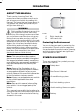
Introduction ABOUT THIS MANUAL Thank you for choosing Ford. We recommend that you take some time to get to know your vehicle by reading this manual. The more that you know about it, the greater the safety and pleasure you will get from driving it. WARNING Driving while distracted can result in loss of vehicle control, crash and injury. We strongly recommend that you use extreme caution when using any device that may take your focus off the road.
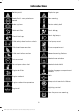
Introduction Battery acid Explosive gas Brake fluid - non petroleum based Fan warning Brake system Fasten safety belt Cabin air filter Front airbag Check fuel cap Front fog lamps Child safety door lock or unlock Fuel pump reset Child seat lower anchor Fuse compartment Child seat tether anchor Hazard warning flashers Cruise control Heated rear window Do not open when hot Heated windshield Engine air filter Interior luggage compartment release Jack Engine coolant Keep out of reach of ch
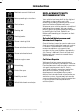
Introduction Maintain correct fluid level REPLACEMENT PARTS RECOMMENDATION Note operating instructions Your vehicle has been built to the highest standards using quality parts. We recommend that you demand the use of genuine Ford and Motorcraft parts whenever your vehicle requires scheduled maintenance or repair. You can clearly identify genuine Ford and Motorcraft parts by looking for the Ford, FoMoCo or Motorcraft branding on the parts or their packaging.
Introduction Warranty on Replacement Parts Genuine Ford and Motorcraft replacement parts are the only replacement parts that benefit from a Ford Warranty. Damage caused to your vehicle as a result of the failure of non-Ford parts may not be covered by the Ford Warranty. For additional information, refer to the terms and conditions of the Ford Warranty. MOBILE COMMUNICATIONS EQUIPMENT Using mobile communications equipment is becoming increasingly important in the conduct of business and personal affairs.
At a Glance Front Exterior Overview A See Locking and Unlocking (page 34). See Keyless Entry (page 36). B See Active City Stop (page 119). C See Changing the Wiper Blades (page 160). D See Maintenance (page 152). E See Towing Points (page 127). F See Changing a Bulb (page 162). G Tire pressures. See Technical Specifications (page 183). H See Changing a Road Wheel (page 179).
At a Glance Vehicle Interior Overview A See Transmission (page 104). B See Locking and Unlocking (page 34). C See Power Windows (page 53). See Exterior Mirrors (page 54). D See Head Restraints (page 83). E See Fastening the Safety Belts (page 21). F See Rear Seats (page 86). G See Manual Seats (page 85). H See Parking Brake (page 109). I See Opening and Closing the Hood (page 152).
At a Glance Instrument Panel Overview Left-Hand Drive 11 B-MAX (CB2) Vehicles Built From: 25-06-2012, Vehicles Built Up To: 31-12-2013
At a Glance Right-Hand Drive A Air vents. See Air Vents (page 75). B Direction indicators. See Direction Indicators (page 51). High beam. See Lighting Control (page 47). C Instrument cluster. See Gauges (page 58). See Warning Lamps and Indicators (page 58). D Start button. See Starting and Stopping the Engine (page 90). E Wiper lever. See Wipers and Washers (page 44). F Information and entertainment display. See Information Displays (page 63). G Audio unit. See Audio System (page 190).
At a Glance K Parking aid switch. See Parking Aids (page 112). L Start-stop switch. See Auto-Start-Stop (page 96). M Card holder or airbag warning lamp. See Passenger Airbag (page 24). N Ignition switch. See Ignition Switch (page 90). O Cruise control switches. See Using Cruise Control (page 117). P Horn. Q Driver knee airbag. See Driver Knee Airbag (page 25). R Steering wheel adjustment. See Adjusting the Steering Wheel (page 42). S Audio control. See Audio System (page 190).
At a Glance Rear Exterior Overview A See Changing a Bulb (page 162). B See Changing the Wiper Blades (page 160). C See Changing a Bulb (page 162). D See First Aid Kit (page 132). See Warning Triangle (page 132). See Temporary Mobility Kit (page 174). Spare wheel, jack, and wheel brace. See Changing a Road Wheel (page 179). Towing eye. See Towing Points (page 127). E See Towing Points (page 127). F Tire pressures. See Technical Specifications (page 183). G See Changing a Road Wheel (page 179).
Child Safety INSTALLING CHILD SEATS WARNINGS If your vehicle has been involved in a crash, have the child seats checked by an authorized dealer. Note: Mandatory use of child seats varies from country to country. Only child seats certified to ECE-R44.03 (or later) have been tested and approved for use in your vehicle. A choice of these are available from an authorized dealer.
Child Safety Child Safety Seat Booster Seat (Group 2) Secure children that weigh between 29 and 40 pounds (13 and 18 kilograms) in a child safety seat (Group 1) on the rear seat. Secure children that weigh more than 33 pounds (15 kilograms) but are less than 59 inches (150 centimeters) tall in a booster seat or a booster cushion. Booster Seats We recommend that you use a booster seat that combines a cushion with a backrest instead of a booster cushion only.
Child Safety ISOFIX Anchor Points Attaching a Child Seat with Top Tethers WARNING WARNINGS Do not attach a tether strap to anything other than the correct tether anchor point. Use an anti-rotation device when using the ISOFIX system. We recommend the use of a top tether or support leg. Make sure that the top tether strap is not slack or twisted and is properly located on the anchor point.
Child Safety CHILD SEAT POSITIONING WARNINGS The child seat must rest tightly against the vehicle seat. It may be necessary to lift or remove the head restraint. See Head Restraints (page 83). WARNINGS See an authorized dealer for the latest details relating to our recommended child seats. Note: When using a child seat on a front seat, always adjust the front passenger's seat to its fully rearward position.
Child Safety ISOFIX Child Seats Mass group categories 0+ 1 Rear facing Forward facing Up to 29 lbs (13 kg) 20 - 40 lbs (9 - 18 kg) Seating positions Front seat Size class Not ISOFIX equipped Seat type Rear outboard seat ISOFIX Rear center seat Size class C, D, E Seat type IL 1 Size class 2 1 A, B, B1 3 IL, IUF Not ISOFIX equipped Seat type IL Suitable for particular ISOFIX child seat systems of the semi-universal category.
Child Safety CHILD SAFETY LOCKS WARNING You cannot open the doors from inside if you have put the child safety locks on. Left-Hand Side Turn counterclockwise to lock and clockwise to unlock. Right-Hand Side Turn clockwise to lock and counterclockwise to unlock.
Safety Belts FASTENING THE SAFETY BELTS WARNINGS Insert the tongue into the buckle until you hear a distinct click. You have not fastened the safety belt correctly if you do not hear a click. Make sure that your safety belt is securely stored away and is not outside your vehicle when closing the door. Pull the belt out steadily. It may lock if you pull it sharply or if your vehicle is on a slope. Press the red button on the buckle to release the belt. Let it retract completely and smoothly.
Safety Belts Using Safety Belts During Pregnancy It will also illuminate when a front safety belt is unfastened when your vehicle is moving. If you do not fasten your safety belt both the audible and visual warnings will switch off automatically after approximately five minutes. Turning the Safety Belt Minder Off See an authorized dealer. WARNING Position the safety belt correctly for your safety and that of your unborn child. Do not use only the lap strap or the shoulder strap.
Supplementary Restraints System Note: You will hear a loud bang and see a cloud of harmless powdery residue if an airbag deploys. This is normal. PRINCIPLE OF OPERATION WARNINGS Extreme Hazard! Never use a rearward facing child restraint on a seat protected by an active airbag in front of it. Death or serious injury to the child can occur. Note: Only wipe airbag covers with a damp cloth. DRIVER AIRBAG Do not modify the front of your vehicle in any way.
Supplementary Restraints System PASSENGER AIRBAG A Switch off B Switch on Turn the switch to position A. When you switch the ignition on, check that the airbag deactivation warning lamp illuminates. The airbag will deploy during significant frontal collisions or collisions that are up to 30 degrees from the left or the right. The airbag will inflate within a few thousandths of a second and deflate on contact with the occupant, thus cushioning forward body movement.
Supplementary Restraints System SIDE CURTAIN AIRBAGS The airbags are located inside the seatback of the front seats. There is a label attached to the side of the seatback to indicate this. The airbags are located over the front and rear side windows. The airbag will deploy during significant lateral collisions. The airbag will not deploy in minor lateral and frontal collisions, rear collisions, or overturns. The airbag will deploy during significant lateral collisions.
Keys and Remote Controls Programming a New Remote Control GENERAL INFORMATION ON RADIO FREQUENCIES 1. Note: Changes or modifications not expressly approved by the party responsible for compliance could void the user’s authority to operate the equipment. 2. The typical operating range for your transmitter is approximately 33 ft (10 m). 3.
Keys and Remote Controls Changing the Remote Control Battery Make sure that you dispose of old batteries in an environmentally friendly way. Seek advice from your local authority regarding recycling. Remote Control With a Folding Key Blade 3. Twist the screwdriver in the position shown to separate the two halves of the remote control. 1. Insert a screwdriver as far as possible into the slot on the side of the remote control, push it toward the key blade and remove the key blade.
Keys and Remote Controls Remote Control Without a Folding Key Blade 4. Twist the screwdriver in the position shown to separate the two halves of the remote control. 1. Press and hold the buttons on the edges to release the cover. Carefully remove the cover. 2. Remove the key blade. Note: Do not touch the battery contacts or the printed circuit board with the screwdriver. 5. Carefully remove the battery with the screwdriver. 6. Install a new battery (3V CR 2032) with the + facing downwards. 3.
Keys and Remote Controls REPLACING A LOST KEY OR REMOTE CONTROL Replacement or additional keys or remote controls can be purchased from an authorized dealer. Your dealer can program the remote controls for your vehicle or you may be able to program them yourself. See Remote Control (page 26). To re-program the passive anti-theft system see an authorized dealer.
MyKey™ Optional Settings PRINCIPLE OF OPERATION You can configure MyKey settings when you first create a MyKey. You can also change the settings afterward with an admin key. The system allows you to program keys with restricted driving modes to promote good driving habits. You can use all but one of the keys programmed to your vehicle with these restricted modes. The following settings can be configured using an admin key: • Various vehicle speed limits can be set.
MyKey™ 4. Select Create MyKey and press OK. 5. When prompted, press and hold OK until you see a message informing you to label this key as a MyKey. The key will be restricted the next time you use it. Note: Make sure you label the MyKey so you can distinguish it from the admin keys. PROGRAMMING A MYKEY Vehicles with Keyless Starting 3. Optional Settings 1. 2. 1. Switch the ignition on using an admin key. 2. Access the main menu using the information display.
MyKey™ MyKey Distance Number of Admin Keys Tracks the distance when drivers use a MyKey. The only way to delete the accumulated distance is by using an admin key to clear your MyKey. If the distance does not accumulate as expected, then the intended user is not using the MyKey, or an admin key user recently cleared and then recreated a MyKey. Indicates how many admin keys are programmed to your vehicle.
MyKey™ Vehicles With Push Button Start Condition Potential Causes I cannot create a MyKey. The key is not in the backup position. See Creating a MyKey (page 30). There are no MyKey driving modes. An admin key is present when you switch the ignition on. There are no MyKeys programmed to your vehicle. See Creating a MyKey (page 30).
Locks Press the button again within three seconds to confirm that all the doors are closed. The doors will lock again, and the turn signals will illuminate if all the doors and the luggage compartment are closed. LOCKING AND UNLOCKING Power Door Locks • Press the button once. The doors will lock. Press the button again. The doors will unlock. For item location: See At a Glance (page 9).
Locks Locking With the Key Turn the top of the key toward the front of your vehicle. Double Locking With the Key Turn the key to the lock position twice within three seconds. Unlocking With the Key Note: If the child safety locks are on and you pull the interior handle, you will only turn off the emergency locking, not the child safety lock. You can only open the doors using the external door handle. Push to lock.
Locks Press the button located in the top of the liftgate pull cup handle to unlatch the liftgate, then pull on the outside handle. MANUAL LIFTGATE WARNINGS It is extremely dangerous to ride in the cargo area, inside or outside of your vehicle. In a collision, people riding in these areas are more likely to be seriously injured or killed. Do not allow people to ride in any area of your vehicle that does not have seats and safety belts.
Locks Note: If the system does not function, you will need to use the key blade to lock and unlock your vehicle. WARNING Your vehicle does not lock itself automatically. If you do not press a locking button your vehicle will remain unlocked. The system allows you to operate your vehicle without the use of a key or remote control. Locking buttons are located on each of the front doors. For central locking and to arm the alarm, press a locking button once.
Locks Unlocking Your Vehicle To enable all your passive keys, unlock your vehicle using a passive key that has not been disabled or the remote control unlocking function. Note: When your vehicle remains locked for longer than three days, the system will enter an energy-saving mode. This is to prevent your vehicle battery running out of charge. When your vehicle is unlocked while in this mode, the reaction time of the system may be a little longer than normal.
Security • • • PASSIVE ANTI-THEFT SYSTEM Principle of Operation The system prevents someone from starting the engine with an incorrectly coded key. Perimeter alarm. Perimeter alarm with interior sensors. Category one alarm with interior sensors and battery back-up sounder. Perimeter Alarm The perimeter alarm is a deterrent against unauthorized access to your vehicle through the doors and the hood. It also protects the audio unit.
Security Triggering the Alarm Ask on Exit (If Equipped) Once armed, the alarm is triggered in any of the following ways: You can set the information display to ask you each time which level of guard you wish to set. • • • • • If someone opens a door, the liftgate or the hood without a valid key or remote control. If someone removes the audio or navigation system. If you switch the ignition on without a valid key. If the interior sensors detect movement within your vehicle.
Security Category One Alarm Disarm and silence the alarm by unlocking the doors with the key and switching the ignition on with a correctly coded key within 12 seconds or unlocking the doors with the remote control. Vehicles with Keyless Entry Note: A valid passive key must be located within the detection range of that door for keyless entry. See Keyless Entry (page 36).
Steering Wheel ADJUSTING THE STEERING WHEEL WARNING Do not adjust the steering wheel when your vehicle is moving. Note: Make sure that you are sitting in the correct position. See Sitting in the Correct Position (page 83). 3. Lock the steering column. AUDIO CONTROL Select the required source on the audio unit. You can operate the following functions with the control: 1. Unlock the steering column. 2. Adjust the steering wheel to the desired position.
Steering Wheel C Volume down D Seek down, previous or accept call CRUISE CONTROL Seek, Next or Previous Press the seek button to: • tune the radio to the next or previous stored preset • play the next or the previous track. Press and hold the seek button to: • tune the radio to the next station up or down the frequency band • seek through a track. See Cruise Control (page 117). VOICE CONTROL Press the button to select or deselect voice control. See SYNC™ (page 239).
Wipers and Washers Intermittent Wipe WINDSHIELD WIPERS Note: Fully defrost the windshield before switching on the windshield wipers. Note: Make sure the windshield wipers are switched off before entering a car wash. Note: Install new wiper blades as soon as they begin to leave bands of water and smears on the windshield. Note: Do not operate the wipers on a dry windshield. This may scratch the glass, damage the wiper blades or cause the wiper motor to burn out.
Wipers and Washers In these conditions, you can do the following to help keep your windshield clear: • Lower the sensitivity of the autowipers. • Change the wiper speed to normal or high speed wipe as necessary. • Switch the autowipers off. Keep the outside of the windshield clean. Sensor performance will be affected if the area around the interior mirror is dirty. The rain sensor is very sensitive and the wipers may operate if dirt, mist or flies hit the windshield.
Wipers and Washers Reverse Gear Wipe The rear wiper will turn on automatically when selecting reverse gear if: • the rear wiper is not already switched on • the wiper lever is in position A, B, C or D • the front wiper is operating (when set to position B). Rear Window Washer Note: Do not operate the washers when the washer reservoir is empty. This may cause the washer pump to overheat. Pull the lever toward you to operate the washers. They will operate for a maximum of 10 seconds.
Lighting GENERAL INFORMATION LIGHTING CONTROL Condensation in Lamp Assemblies Lighting Control Positions Exterior lamps have vents to accommodate normal changes in air pressure. Condensation can be a natural by-product of this design. When moist air enters the lamp assembly through the vents, there is a possibility that condensation can occur when the temperature is cold. When normal condensation occurs, a fine mist can form on the interior of the lens.
Lighting High Beams Pull the lever fully toward you to switch the high beams on. The headlamps will switch on and off automatically in low light situations or during inclement weather. Push the lever forward to switch the high beams off. The headlamps will remain on for a period of time after you switch the ignition off. You can adjust the time delay using the information display controls. See Information Displays (page 63).
Lighting INSTRUMENT LIGHTING DIMMER DAYTIME RUNNING LAMPS WARNING Always remember to switch your headlamps on in low light situations or during inclement weather. The system does not turn on the tail lamps and may not provide adequate lighting during these conditions. Failure to switch the headlamps on under these conditions may result in a collision. The system switches the headlamps on in low light situations. To switch the system on: 1. Switch the ignition on. 2.
Lighting Note: Only use fog lamps during reduced visibility, for example, fog, snow or heavy rain. Note: Do not use the rear fog lamps when it is raining or snowing. Note: If you switch autolamps on, you can only switch the fog lamps on once autolamps has turned the headlamps on. Note: If you switch autolamps on, you can only switch the fog lamps on once autolamps has turned the headlamps on. HEADLAMP LEVELING REAR FOG LAMPS Note: Vehicles with Xenon headlamps have automatic headlamp leveling. 1.
Lighting Recommended Headlamp Leveling Switch Positions Load 1 Load in luggage compartment Switch position - - 0 2 3 - 2 3 1 - Front seats Second row seats 1-2 1.5 Max 1 2.5 Max 1 3.5 See Vehicle Identification Plate (page 186). INTERIOR LAMPS DIRECTION INDICATORS Courtesy Lamp Push the lever up or down to use the direction indicators. Note: Tap the lever up or down to make the direction indicators flash three times to indicate a lane change.
Lighting The courtesy lamp will also illuminate when you switch the ignition off. It will go off automatically after a short time or when you start the engine. If you set the switch to position C with the ignition switched off, the courtesy lamp will illuminate. It will go off automatically after a short time to prevent your vehicle battery from losing charge. To switch it back on, switch the ignition on for a short time.
Windows and Mirrors Window Lock POWER WINDOWS WARNINGS Do not leave children unattended in your vehicle and do not let them play with the power windows. They may seriously injure themselves. When closing the power windows, you should verify they are free of obstructions and make sure that children and pets are not in the proximity of the window openings. Press the control to lock or unlock the rear window controls. It will illuminate when the rear window controls are locked.
Windows and Mirrors 2. Close the window a third time to the point of resistance. The bounce-back feature is now disabled and you can close the window manually. The window will go past the point of resistance and you can close it fully. EXTERIOR MIRRORS Power Exterior Mirrors WARNING Do not adjust the mirrors when your vehicle is moving. See an authorized dealer as soon as possible if the window does not close after the third attempt.
Windows and Mirrors Fold-Away Exterior Mirrors The mirrors will fold automatically when you lock your vehicle with the key, the remote control or a keyless entry system request. The mirrors will unfold when you unlock your vehicle with the key, the remote control, a keyless entry system request, the driver's interior door handle or starting the engine. Push the mirror toward the door window glass. Make sure that you fully engage the mirror in its support when returning it to its original position.
Windows and Mirrors Global Opening CHILDMINDER MIRROR To open all the windows: 1. Press and release the remote control unlock button. 2. Press and hold the remote control unlock button for at least three seconds. GLOBAL OPENING AND CLOSING You can also operate the power windows with the ignition off using the global opening and global closing function. Press the lock or unlock button to stop the opening function.
Windows and Mirrors To close all the windows, press and hold the driver’s door handle for at least three seconds. The bounce-back function is also on during global closing. To close all the windows, press and hold the remote control lock button for at least three seconds. Press the lock or unlock button to stop the closing function. The bounce-back function is also on during global closing. Vehicles With Keyless Entry WARNING Take care when using global closing.
Instrument Cluster GAUGES A Tachometer B Information display C Speedometer D Fuel gauge E Tripmeter reset button Fuel Gauge WARNING LAMPS AND INDICATORS Switch the ignition on. The fuel gauge will indicate approximately how much fuel is left in the fuel tank. The fuel gauge may vary slightly when your vehicle is moving or on a gradient. The arrow adjacent to the fuel pump symbol indicates on which side of your vehicle the fuel filler door is located.
Instrument Cluster • • • Oil pressure. Power steering. Stability control. If it illuminates when you are driving, this indicates a malfunction. Stop your vehicle as soon as it is safe to do so and switch the engine off. Check the coolant level. See Engine Coolant Check (page 158). When a warning lamp or indicator does not illuminate once you have switched the ignition on, it indicates a malfunction. Have the system checked by an authorized dealer.
Instrument Cluster Exterior Lamps On Indicator WARNING Have this checked immediately. It will illuminate when you switch the headlamp low beam or the side and tail lamps on. If both lamps illuminate together, stop your vehicle as soon as it is safe to do so (continued use may cause reduced power and cause the engine to stop). Switch the ignition off and attempt to restart the engine. If the engine restarts have the system checked by an authorized dealer immediately.
Instrument Cluster Oil Pressure Warning Lamp Stability Control Indicator While driving, it flashes when the system is operating. After you switch the ignition on, if it does not illuminate or illuminates continuously while driving, this indicates a malfunction. During a malfunction, the system switches off. Have the system checked by an authorized dealer as soon as possible. WARNING Do not resume your journey if it illuminates despite the level being correct.
Instrument Cluster Safety Belt Minder WARNINGS The safety belt minder remains in stand-by mode when the front safety belts have been fastened. It will sound if either safety belt is unfastened. Do not sit on top of a fastened safety belt to prevent the safety belt minder from coming on. The occupant protection system will only provide optimum protection when you use the safety belt properly. Sounds when your vehicle speed exceeds the pre-determined limit and the front safety belts are unfastened.
Information Displays Information Display Controls GENERAL INFORMATION WARNING Driving while distracted can result in loss of vehicle control, crash and injury. We strongly recommend that you use extreme caution when using any device that may take your focus off the road. Your primary responsibility is the safe operation of your vehicle. We recommend against the use of any hand-held device while driving and encourage the use of voice-operated systems when possible.
Information Displays SYNC-Phone Dial a number Redial Phonebook Call history Speed Dial Text messaging BT Devices Phone settings Menu Ford EcoMode SYNC-Settings Bluetooth on Set defaults Master reset Install on SYNC System info Voice settings SYNC-Apps Navigation Route options Map display Assistance options Personal data Reset all settings Audio settings Adaptive volume Sound NAV audio mixing 64 B-MAX (CB2) Vehicles Built From: 25-06-2012, Vehicles Built Up To: 31-12-2013
Information Displays Menu DSP settings DSP equalizer Traffic News Alt.
Information Displays Menu Active City Stop Speed limit Speed warning Volume limit Information Clear all MyKeys MyKey active Information System Check TRIP COMPUTER All active warnings will display first if applicable. The system check menu may appear different based upon equipment options and current vehicle status. Press the up or down arrow button to scroll through the list. CLOCK Type 1 Press the button to scroll through the displays.
Information Displays Distance to Empty PERSONALIZED SETTINGS Indicates the approximate distance your vehicle will travel on the fuel remaining in the tank. Changes in driving pattern may cause the value to vary. Measure Units To swap between imperial and metric units, scroll to this display and press the OK button. Swapping between imperial and metric units will affect the following displays: • Distance to empty. • Average fuel consumption. • Instantaneous fuel consumption. • Average speed.
Information Displays Certain messages need to be confirmed before you can access the menus. Some messages will be supplemented by a system specific symbol with a message indicator. The message indicator illuminates to supplement some messages. It will be red or amber depending on the severity of the message and will remain on until the cause of the message has been rectified.
Information Displays Message Message indicator Action red Vehicle is moving. Stop your vehicle as soon as safely possible and close. red Vehicle is moving. Stop your vehicle as soon as safely possible and close. See Opening and Closing the Hood (page 152). Boot open Bonnet open Driver door open amber Vehicle not moving. Close. Driver's rear door open amber Vehicle not moving. Close. Passenger door open amber Vehicle not moving. Close. Passenger rear door open amber Vehicle not moving.
Information Displays Keyless System Message Message indicator Action Key not detected amber See Keyless Entry (page 36). Key outside car amber See Keyless Entry (page 36). Key Battery low Replace battery amber See Remote Control (page 26). Turn ignition off Use POWER button amber See Keyless Starting (page 90). To start press brake - See Keyless Starting (page 90). To start press clutch - See Keyless Starting (page 90). Close boot or use spare key - See Keyless Entry (page 36).
Information Displays Message indicator Action Engine malfunction Service now amber Have your vehicle checked by an authorized dealer as soon as possible. Auto wiper/lights malfunction Next service amber Have your vehicle checked by an authorized dealer as soon as possible. - Have your vehicle checked by an authorized dealer as soon as possible.
Information Displays Message indicator Action Buckle up to unmute audio - Displays when a MyKey is in use and BeltMinder is activated. MyKey Park aid cannot be deactivated - Displays when a MyKey is in use and park aid is activated. MyKey ESC cannot be deactivated - Displays when programming a MyKey. Message Steering Message indicator Action Steering malfunction Service now red Have your vehicle checked by an authorized dealer as soon as possible.
Information Displays Transmission Message indicator Action red Have your vehicle checked by an authorized dealer as soon as possible. red The transmission is overheating and needs to cool. Stop your vehicle as soon as it is safe to do so. Move the transmission selector lever to position N or P and apply the parking brake. Switch off the ignition until the transmission has cooled and the message disappears from the display. Vehicle not in Park Select P - See Automatic Transmission (page 104).
Information Displays Tire Pressure Monitoring System Message Message indicator Action Check Tire pressures amber The pressure in one or more tires has dropped. Check as soon as possible. Tire pressure sys malfunction service required amber Have your vehicle checked by an authorized dealer as soon as possible.
Climate Control Warming the Interior PRINCIPLE OF OPERATION Direct the air toward your feet. In cold or humid weather conditions, direct some of the air toward the windshield and the door windows. Outside Air Keep the air intakes in front of the windshield free from obstruction (such as snow or leaves) to allow the climate control system to function effectively. Cooling the Interior Direct the air toward your face.
Climate Control MANUAL CLIMATE CONTROL A Fan speed control: Controls the volume of air circulated in your vehicle. Adjust to select the desired fan speed or switch off. If you switch the fan off, the windshield may fog up. B On and off: Press the button to turn the system on and off. When the system is off, outside air is prevented from entering your vehicle. C Recirculated air: Press the button to switch between outside air and recirculated air.
Climate Control H Heated front seats: Press the button to turn the heated seats on. See Heated Seats (page 87). I Air conditioning: Press the button to switch the air conditioning on or off. Air conditioning cools your vehicle using outside air. To improve air conditioning when starting your vehicle, drive with the windows slightly open for two to three minutes. AUTOMATIC CLIMATE CONTROL A Fan speed: Controls the volume of air circulated in your vehicle.
Climate Control F Windshield: Press the button to distribute air through the windshield air vents. You can also use this setting to defog and clear the windshield of a thin covering of ice. G Heated windshield: Press the button to defog and clear the windshield of a thin covering of ice. H Temperature control: Controls the temperature of the air circulated in your vehicle. Adjust to select the desired temperature.
Climate Control Temperature Control Note: Do not place objects under the front seats as this may interfere with the airflow to the rear seats. Note: Remove any snow, ice or leaves from the air intake area at the base of the windshield. Manual Climate Control Note: To reduce fogging of the windshield during humid weather, adjust the air distribution control to the windshield air vents position. Increase the temperature and fan speed to improve clearing, if required.
Climate Control Heating the Interior Quickly Vehicles With Manual Climate Control Vehicles With Automatic Climate Control 1 Adjust the fan speed to the highest speed setting. Adjust the fan speed to the highest speed setting. 2 Adjust the temperature control to the highest setting. Adjust the temperature control to the highest setting. 3 Adjust the air distribution control to the Press the footwell button to distribute footwell air vents position. air to the footwell air vents.
Climate Control Recommended Settings for Cooling Vehicles With Manual Climate Control Vehicles With Automatic Climate Control 1 Adjust the fan speed to the second speed setting. Press the AUTO button. 2 Adjust the temperature control to the midway point of the cold settings. Adjust the temperature control to the desired setting. 3 Adjust the air distribution control to the Open all instrument panel air vents and instrument panel air vents position. direct as desired.
Climate Control Vehicles With Manual Climate Control 4 Adjust the fan speed to the highest setting. 5 Direct the instrument panel side air vents toward the side windows. 6 Close the instrument panel vents. Vehicles With Automatic Climate Control Maximum Cooling Performance in Instrument Panel or Instrument Panel and Footwell Positions Heated Windshield 1. Heated Rear Window Adjust the temperature control to the lowest setting. 2. Press the A/C and recirculated air buttons. 3.
Seats • SITTING IN THE CORRECT POSITION WARNINGS Do not recline the seatback too far as this can cause the occupant to slide under the safety belt, resulting in serious injury in the event of a collision. • Sitting improperly, out of position or with the seatback reclined too far, can result in serious injury or death in the event of a collision. Always sit upright against your seatback, with your feet on the floor.
Seats Rear Outer Head Restraint 1. Press button A to move the restraint rearward. 2. To move the restraint forward pull the headrest. 1. Press and hold the locking button. 2. Using a suitable implement release the retaining clip. Rear Center Head Restraint Removing the Head Restraint Press the locking buttons and remove the head restraint. 1. Press and hold the locking button. 2. Using a suitable implement release the retaining clip.
Seats Adjusting the Height of the Driver’s Seat MANUAL SEATS WARNINGS Do not place cargo or any objects behind the seatback before returning it to the original position. Pull on the seatback to make sure that it has fully latched after returning the seatback to its original position. An unlatched seat may become dangerous if you stop suddenly or have a collision. Rock the seat backward and forward after releasing the lever to make sure that it is fully engaged in its catch.
Seats 1. Push the locking lever 2. Fold the seat forward. Make sure that the seatback is in the folded position and securely latched. 3. Push the locking lever to return the seatback to the vertical position. Make sure that the seatback is securely latched in position. 1. Press the unlock buttons down and hold them there. 2. Push the seatback forward. As the rear seatback lowers the seat cushion will also lower.
Seats HEATED SEATS FRONT SEAT ARMREST WARNING People who are unable to feel pain to their skin because of advanced age, chronic illness, diabetes, spinal cord injury, medication, alcohol use, exhaustion or other physical conditions, must exercise care when using the heated seat. The heated seat may cause burns even at low temperatures, especially if used for long periods of time. Do not place anything on the seat that insulates against heat, such as a blanket or cushion.
Auxiliary Power Points 12 Volt DC Power Point Location Power points may be found: • on the center console • on the rear of the center console. WARNING Do not plug optional electrical accessories into the cigar lighter socket. Incorrect use of the lighter can cause damage not covered by your warranty, and can result in fire or serious injury. CIGAR LIGHTER Note: Do not hold the cigar lighter element pressed in.
Storage Compartments CUP HOLDERS WARNING Do not place hot drinks in the cup holders when your vehicle is moving.
Starting and Stopping the Engine GENERAL INFORMATION IGNITION SWITCH WARNINGS Extended idling at high engine speeds can produce very high temperatures in the engine and exhaust system, creating the risk of fire or other damage. Do not park, idle or drive your vehicle on dry grass or other dry ground cover. The emission system heats up the engine compartment and exhaust system, creating the risk of fire. 0(off) - The ignition is off.
Starting and Stopping the Engine Starting a Diesel Engine Note: A valid key must be located inside your vehicle to switch the ignition on and start the engine. Note: Engine cranking will not commence until the engine glow plug indicator has extinguished. This may take several seconds in extremely cold conditions. Ignition On Press the button once. It is located on the instrument panel near the steering wheel.
Starting and Stopping the Engine Stopping the Engine When Your Vehicle is Stationary STEERING WHEEL LOCK VEHICLES WITHOUT: KEYLESS ENTRY AND PUSH BUTTON START/PUSH BUTTON START Note: The ignition, all electrical circuits warning lamps and indicators will be switched off. WARNING Manual Transmission Always check that the steering is unlocked before attempting to move your vehicle. Press the button. Automatic Transmission 1. Move the transmission selector lever to position P. 2. Press the button.
Starting and Stopping the Engine Unlocking the Steering Wheel Switch the ignition on to unlock the steering wheel. If you have difficulty starting the engine when the temperature is below -13°F (-25°C), press the accelerator pedal to the mid-way point of its travel and try again. Note: You may have to rotate the steering wheel slightly to assist unlocking. Flooded Engine Vehicles with Manual Transmission STARTING A GASOLINE ENGINE 1. Fully depress the clutch pedal. 2.
Starting and Stopping the Engine 2. Turn the key to position III until the engine has started. Failure to Start STARTING A DIESEL ENGINE If the engine does not crank when the clutch pedal has been fully depressed and the ignition key is turned to position III. Vehicles With Manual Transmission Cold or Hot Engine 1. Fully depress the clutch and brake pedals. 2. Turn the key to position III until the engine has started.
Starting and Stopping the Engine A normal filter requires periodic replacement. The diesel particulate filter on your vehicle requires periodic regeneration to maintain its correct function. Your vehicle will carry out this process automatically. Release the accelerator pedal. Wait until the engine has reached idle speed and then switch it off. If your journeys meet one of the following conditions: • You drive only short distances. • You frequently switch the ignition on and off.
Unique Driving Characteristics AUTO-START-STOP Note: For vehicles with start-stop the battery requirement is different. It must be replaced by one of exactly the same specification as the original. Note: When the start-stop indicator flashes amber, move the transmission selector lever to neutral or depress the clutch pedal. Note: If the system detects a malfunction, it will switch off. Have your vehicle checked by an authorized dealer.
Unique Driving Characteristics To Re-Start the Engine Note: The transmission selector lever must be in neutral. Depress the clutch pedal. The system may automatically restart the engine under certain conditions, for example: • Low battery voltage. • To maintain the interior climate.
Fuel and Refueling • SAFETY PRECAUTIONS WARNINGS Do not overfill the fuel tank. The pressure in an overfilled tank may cause leakage and lead to fuel spray and fire. The fuel system may be under pressure. If you hear a hissing sound near the fuel filler door (Easy Fuel capless fuel system), do not refuel until the sound stops. Otherwise, fuel may spray out, which could cause serious personal injury. • Automotive fuels can cause serious injury or death if misused or mishandled.
Fuel and Refueling FUEL QUALITY - GASOLINE WARNINGS Use diesel that meets the specification defined by EN 590 or the relevant national specification. WARNINGS Do not mix gasoline with oil, diesel or other liquids. This could cause a chemical reaction. Note: We recommend that you use only high quality fuel. Do not use leaded gasoline or gasoline with additives containing other metallic compounds (e.g. manganese-based). They could damage the emission system.
Fuel and Refueling Refilling With a Portable Fuel Container 1. Locate the plastic funnel in the glove box. 2. Slowly insert the funnel into the capless fuel system. 3. Fill your vehicle with fuel from the portable fuel container. 4. When done, clean the funnel or properly dispose of it. Extra funnels can be purchased from your authorized dealer if you choose to dispose of the funnel. WARNINGS Do not insert the nozzle of portable fuel containers or aftermarket funnels into the capless fuel system.
Fuel and Refueling REFUELING WARNINGS Do not attempt to start the engine if you have filled the fuel tank with the incorrect fuel. This could damage the engine. Have the system checked by an authorized dealer immediately. Do not use any kind of flames or heat near the fuel system. The fuel system is under pressure. There is a risk of injury if the fuel system is leaking. 1.
Fuel and Refueling FUEL CONSUMPTION Note: The amount of usable fuel in the empty reserve varies and should not be relied upon to increase driving range. When refueling your vehicle after the fuel gauge indicates empty, you might not be able to refuel the full amount of the advertised capacity of the fuel tank due to the empty reserve still present in the tank.
Fuel and Refueling Calculating Fuel Economy 4. Subtract your initial odometer reading from the current odometer reading. 5. Calculate fuel economy by dividing miles traveled by gallons used (For Metric: Multiply liters used by 100, then divide by kilometers traveled). Do not measure fuel economy during the first 1000 miles (1600 km) of driving (this is your engine’s break-in period). A more accurate measurement is obtained after 2000 - 3000 miles (3200 - 4800 km).
Transmission Selector Lever Positions MANUAL TRANSMISSION Selecting Reverse Gear Do not engage reverse gear when your vehicle is moving. This can cause damage to the transmission. AUTOMATIC TRANSMISSION WARNINGS Always set the parking brake fully and make sure you move the transmission selector lever to position P. Switch the ignition off and remove the key whenever you leave your vehicle. Do not apply the brake pedal and accelerator pedal simultaneously.
Transmission Select drive to shift automatically through the forward gears. WARNINGS Apply the parking brake and move the transmission selector lever to park before leaving your vehicle. Make sure that the transmission selector lever is latched in position. The transmission will select the appropriate gear for optimum performance based on ambient temperature, road gradient, vehicle load and your input.
Transmission Hints on Driving With an Automatic Transmission Emergency Park Position Release Lever WARNING WARNINGS Do not drive your vehicle until you verify that the brake lamps are working. Do not idle the engine for long periods of time in drive with the brakes applied. If the parking brake is fully released, but the brake warning lamp remains illuminated, the brakes may not be working correctly. See an authorized dealer. Moving Off 1. Release the parking brake. 2.
Transmission The system makes it easier to pull away when your vehicle is on a slope without the need to use the parking brake. When the system is active, your vehicle will remain stationary on the slope for two to three seconds after you release the brake pedal. This allows you time to move your foot from the brake to the accelerator pedal. The brakes are released automatically once the engine has developed sufficient drive to prevent your vehicle from rolling down the slope.
Transmission Your vehicle comes with the system already enabled. If desired, you can disable the feature: See General Information (page 63).
Brakes GENERAL INFORMATION HINTS ON DRIVING WITH ANTI-LOCK BRAKES WARNING Note: When the system is operating, the brake pedal will pulse and may travel further. Maintain pressure on the brake pedal. You may also hear a noise from the system. This is normal. The system does not relieve you of your responsibility to drive with due care and attention. Note: Occasional brake noise is normal. If a metal-to-metal, continuous grinding or continuous squeal sound is present, the brake linings may be worn-out.
Brakes Note: If you park your vehicle on a hill and facing downhill select reverse gear and turn the steering wheel toward the curb. All Vehicles Note: Do not press the release button while pulling the lever up. To apply the parking brake: 1. Press the foot brake pedal firmly. 2. Pull the parking brake lever up to its fullest extent. To release the parking brake: 1. Press the brake pedal firmly. 2. Pull the lever up slightly. 3. Press the release button and push the lever down.
Stability Control PRINCIPLE OF OPERATION Stability Control Warning Lamp Electronic Stability Program While driving, it flashes when the system is operating. See Warning Lamps and Indicators (page 58). WARNING The system does not relieve you of your responsibility to drive with due care and attention. Failure to do so could result in loss of vehicle control, personal injury or death. USING STABILITY CONTROL Note: The system automatically switches on every time you switch the ignition on.
Parking Aids Note: The outer sensors may detect the side walls of a garage. If the distance between the outer sensors and the side wall remains constant for three seconds, the alert will turn off. As you continue the inner sensors will detect objects directly behind your vehicle. PRINCIPLE OF OPERATION WARNINGS The system does not relieve you of your responsibility to drive with due care and attention. If your vehicles has a non-Ford approved trailer tow module the system may not correctly detect objects.
Parking Aids The parking aid system gives an audible warning and reduces the radio volume when it detects a large object within a limited range of your vehicle’s bumpers.
Parking Aids • • A The front parking aid sensor coverage area is up to 31 inches (80 centimeters) from the center of your vehicle’s front bumper and up to 14 inches (35 centimeters) to the side of your vehicle’s front bumper. The rear parking aid sensor coverage area is up to 72 inches (183 centimeters) from the center of your vehicle’s rear bumper. There is a decreased coverage area at the outer corners.
Parking Aids Using the Display WARNINGS Do not place objects in front of the camera. WARNINGS Obstacles above the camera position will not be shown. Inspect the area behind your vehicle if necessary. The camera is located on the liftgate near the handle. Marks are for general guidance only, and are calculated for vehicles in maximum load conditions on an even road surface. The lines show the distance from the outer edge of the front tire plus two inches (51 millimeters) and the rear bumper.
Parking Aids C Green - 24 - 35 inches (0.6 - 0.9 meter) D Black - center line of the projected vehicle path Note: The green line is extended from 35 inches (0.9 meter) up to a distance of 126 inches (3.2 meters). Note: When reversing with a trailer, the lines on the screen are not shown. The camera will show your vehicle direction and not the trailer. Switching the Rear View Camera Off Note: The system will automatically switch off once your vehicle speed has reached approximately 7 mph (12 km/h).
Cruise Control PRINCIPLE OF OPERATION WARNING The system does not relieve you of your responsibility to drive with due care and attention. Cruise control allows you to control your speed using the switches on the steering wheel. You can use cruise control when you exceed approximately 20 mph (30 km/h). The cruise controls are located on the steering wheel.
Cruise Control Resuming the Set Speed Press and release RES. Switching Cruise Control Off Note: You will erase the set speed if you switch the system off. Press and release OFF or switch the ignition off.
Driving Aids ACTIVE CITY STOP WARNINGS If you install a windshield not approved by us, the system may not function correctly. General Information WARNINGS The system does not relieve you of your responsibility to drive with due care and attention. If the engine stops after the system has been switched on, the hazard warning flashers will turn on. The system may not function when driving around sharp curves.
Driving Aids Laser Sensor Information In certain situations it is advisable to disable the system, for example: • Driving off road when objects may cover the windshield. • Driving through a car wash facility. You can switch the system off and on using the information display. See General Information (page 63). Active City Stop Relearning Procedure Note: When you disconnect the battery, the system will go through a relearning procedure. During this time the system will not be available.
Load Carrying GENERAL INFORMATION REAR UNDER FLOOR STORAGE WARNINGS Use load securing straps to an approved standard, e.g. DIN. Adjustable Load Floor Make sure that you secure all loose items properly. Place luggage and other loads as low and as far forward as possible within the luggage or loadspace. Do not drive with the liftgate or rear door open. Exhaust fumes may enter your vehicle. Do not exceed the maximum front and rear axle loads for your vehicle. See Vehicle Identification Plate (page 186).
Load Carrying Removing the Cover CARGO NETS Installing and Removing the Net Installing the Net DOG GUARD WARNING Keep a small distance between the dog guard and the rear seats. 1. Raise the rear outer head restraints. See Head Restraints (page 83). 2. Attach the top securing clips to the head restraint guides. 3. Attach the bottom securing clips to the bottom anchor points. Removing the Net 1. Raise the rear outer head restraints. See Head Restraints (page 83). 2.
Load Carrying 123 B-MAX (CB2) Vehicles Built From: 25-06-2012, Vehicles Built Up To: 31-12-2013
Towing • TOWING A TRAILER WARNINGS Do not exceed 62 mph (100 km/h). This could result in the loss of vehicle control, serious personal injury or death. The rear tire pressures must be increased by 3 psi (0.2 bar) above specification. Do not exceed the maximum pressure stated on the tire sidewall. This could cause serious personal injury. See Wheels and Tires (page 174). • • Do not exceed the maximum gross train weight stated on your vehicle identification plate.
Towing Unlocking the Tow Ball Arm Mechanism Note: Not all vehicles are suitable or approved to have tow bars fitted. See an authorized dealer for further information. Trailer Lighting The electrical system on your vehicle is not suitable for towing trailers with LED lamps. TOW BALL WARNINGS When not in use, always transport the tow ball arm securely fastened in the luggage compartment. 1. Remove the protecting cap. 2. Insert the key and turn it clockwise to unlock. 3. Hold the tow ball arm.
Towing Before starting your journey, make sure that the tow ball arm is correctly locked. Check that: • • • • Note: Pull out the plug. Removing the Tow Ball Arm 1. Insert the tow ball arm vertically and press it upwards until it engages. Note: Do not hold your hand near the handwheel. Note: The green mark on the handwheel must align with the green mark on the tow ball. 2. Turn the key counterclockwise and remove the key to lock the tow ball. 3.
Towing Maintenance Note: Unhitch the trailer. 1. Remove the protecting cap. Press the cap into the key bow. Insert the key and unlock. 2. Hold the tow ball arm. Pull the handwheel out, turn it clockwise against the stop. 3. Remove the tow ball arm. 4. Release the handwheel. WARNING Remove the tow ball arm and protect the seat with the plug before steam cleaning your vehicle. Keep the system clean.
Towing Rear Towing Hook Drive off slowly and smoothly without jerking the vehicle that is being towed. You must only use the towing eye that was delivered with your vehicle. See Towing Points (page 127). Tow ropes or rigid towing bars must be placed on the same side. For example; right hand rear towing point to right hand front towing point. You must use a tow rope or rigid towing bar that is of the correct strength for the weight of the towing vehicle and the vehicle that is being towed.
Towing Note: Using a rigid towing bar is the safest way to tow a vehicle. WARNINGS The brake and steering assistance will not operate unless the engine is running. Press the brake pedal harder and allow for increased stopping distances and heavier steering. Failure to take care may lead to a crash or personal injury. The weight of the vehicle that is being towed must not exceed the weight of the towing vehicle.
Driving Hints BREAKING-IN WARNINGS Engine damage can occur if water enters the air filter. Tires WARNING In an emergency, you can drive your vehicle through water to a maximum depth of 8 inches (200 millimeters) and at a maximum speed of 6 mph (10 km/h). You must take extra care when driving through flowing water. New tires need to be run-in for approximately 300 miles (500 kilometers). During this time, you may experience different driving characteristics.
Driving Hints WARNINGS Always use floor mats that are designed to fit the foot well of your vehicle, leaving the pedal area unobstructed, and which can be firmly secured to retention posts so that they cannot slip out of position and interfere with the pedals or impair safe operation of your vehicle in other ways. Incorrectly fitted floor mats can cause the accelerator pedal to become stuck in the open position. This can cause loss of vehicle control.
Roadside Emergencies HAZARD WARNING FLASHERS WARNINGS Always use booster cables with insulated clamps and adequate size cable. The hazard warning button is located on the instrument panel. Use it when your vehicle is creating a safety hazard for other motorists. Note: Do not disconnect the battery from your vehicle’s electrical system. To Connect the Booster Cables Press the button to turn on the hazard warning function, and the front and rear direction indicators will flash.
Roadside Emergencies 3. Connect the positive (+) terminal of vehicle B with the positive (+) terminal of vehicle A (cable C). Disconnect the cables in the reverse order. 4. Connect the negative (-) terminal of vehicle B to the ground connection of vehicle A (cable D). WARNINGS Do not connect directly to the negative (–) terminal of the battery with low charge. Make sure that the cables are clear of any moving parts and fuel delivery system parts. To Start the Engine 1.
Fuses Passenger Compartment Fuse Box FUSE BOX LOCATIONS This fuse box is located behind the glove box. Open the glove box and empty the contents. Press the sides inwards and swivel the glove box downward.
Fuses FUSE SPECIFICATION CHART - VEHICLES BUILT UP TO: 04-012013 Engine Compartment Fuse Box Fuse Fuse rating Circuits protected 1 40 A Anti-lock braking system module 1 30 A Anti-lock braking system, electronic stability program module 2 60 A Cooling system fan high speed 3 40 A Cooling system fan 3 30 A Cooling system fan low speed 4 30 A Heater blower 135 B-MAX (CB2) Vehicles Built From: 25-06-2012, Vehicles Built Up To: 31-12-2013
Fuses Fuse Fuse rating Circuits protected 5 60 A Passenger's compartment fuse box supply (battery) 6 30 A Body control module 7 60 A Passenger's compartment fuse box supply (ignition) 8 60 A Glow plugs 8 50 A DPS6 module 9 40 A Heated windshield 10 40 A Heated windshield 11 30 A Starter relay 12 10 A High beam left-hand relay 13 10 A High beam right-hand relay 14 15 A Run on pump 15 20 A Ignition coil 16 15 A Powertrain control module, high and low cooling fan 17 1
Fuses Fuse Fuse rating Circuits protected 30 - Not used 31 - Not used 32 20 A Horn, battery saver, keyless vehicle module 33 20 A Heated rear window 34 20 A Fuel pump relay, diesel fuel heater 35 15 A Cat1 alarm system 36 7.
Fuses Passenger's Compartment Fuse Box - Type 1 Fuse Fuse rating Circuits protected 1 7.5 A Ignition, rain sensor, heated windshield 2 10 A Stop lamps 3 7.5 A Reversing lamp, rear view camera 4 7.
Fuses Fuse Fuse rating Circuits protected 13 10 A Ignition, electric power assisted steering, instrument cluster, passive anti-theft system, anti-lock braking system 14 7.5 A Powertrain control module, transmission selector lever, fuel pump 15 7.5 A Audio system, instrument cluster 16 7.
Fuses Passenger's Compartment Fuse Box - Type 2 Fuse Fuse rating Circuits protected 1 7.5 A Ignition, rain sensor, heated windshield, dome lamp, interior mirror 2 10 A Stop lamps 3 7.5 A Reversing lamp 4 7.
Fuses Fuse Fuse rating Circuits protected 6 15 A Rear window wiper 7 15 A Washer pump 8 - Not used 9 15 A Passenger's heated seat 10 15 A Driver's heated seat 11 - 12 10 A Airbag module 13 10 A Ignition, electric power assisted steering, instrument cluster, passive anti-theft system, anti-lock braking system 14 7.5 A Powertrain control module, gear selector lever, fuel pump 15 7.5 A Audio system, instrument cluster 16 7.
Fuses Fuse Fuse rating Circuits protected 26 30 A Front wiper, left-hand side 27 30 A Front wiper, right-hand side 28 30 A Voltage quality module 29 20 A Rear power point 30 20 A Cigar lighter, front power point 31 - Not used 32 - Not used 33 - Not used 34 20 A Keyless entry 35 20 A Keyless entry 36 10 A Data link connector 37 15 A Ignition switch 38 - Not used 39 - Not used 40 - Not used 41 - Not used 42 7.
Fuses Relay Circuits switched R1 Ignition R2 Cigar lighter R3 Not used R4 Active city stop relay R5 Not used R6 Keyless entry (accessory) R7 Keyless entry (ignition) R8 Battery saver relay R9 Heated front screen left-hand side R10 Heated front screen right-hand side R11 Not used R12 Not used 143 B-MAX (CB2) Vehicles Built From: 25-06-2012, Vehicles Built Up To: 31-12-2013
Fuses FUSE SPECIFICATION CHART - VEHICLES BUILT FROM: 05-012013 Engine Compartment Fuse Box Fuse Fuse rating 1 30 A Anti-lock brake system module Stability assist module 2 60 A Cooling system fan high speed 40 A Cooling system fan 30 A Cooling system fan low speed 4 30 A Heater blower 5 60 A Passenger compartment fuse box supply (battery) 3 Circuits protected 144 B-MAX (CB2) Vehicles Built From: 25-06-2012, Vehicles Built Up To: 31-12-2013
Fuses Fuse Fuse rating 6 30 A Body control module 7 60 A Passenger compartment fuse box supply (ignition) 60 A Glow plugs (Diesel engines) 8 Circuits protected 50 A DPS6 module 9 40 A Heated windshield left-hand side 10 40 A Heated windshield right-hand side 11 30 A Starter relay 12 10 A High beam left-hand relay 13 10 A High beam right-hand relay 14 15 A Run on pump 15 20 A Ignition coil 16 15 A Powertrain control module High and low cooling fan 17 15 A Heated oxygen
Fuses Fuse Fuse rating Circuits protected 30 - Not used 31 - Not used 32 20 A Horn Battery saver Keyless vehicle module 33 20 A Heated rear window 34 20 A Fuel pump relay Diesel fuel heater 35 15 A Category 1 alarm system 36 7.
Fuses Relay Circuits switched Diesel fuel heater R12 Reversing lamp R13 Heater blower Passenger Compartment Fuse Box Fuse Fuse rating 1 7.
Fuses Fuse Fuse rating Circuits protected Heated windshield Dome lamp Interior mirror 2 10 A Stop lamps 3 3A Reversing lamp 4 7.5 A Headlamp leveling 5 - 6 15 A Rear window wiper 7 15 A Washer pump 8 - 9 15 A Passenger heated seat 10 15 A Driver heated seat 11 - 12 10 A Airbag module 13 10 A Ignition Electric power assisted steering Instrument cluster Passive anti-theft system Anti-lock brake system 14 7.
Fuses Fuse Fuse rating Circuits protected Navigation 22 7.5 A Instrument cluster 23 7.
Fuses Fuse Fuse rating Circuits protected 44 7.
Fuses If electrical components in your vehicle are not working, a fuse may have blown. A break in the fuse wire will indicate a blown fuse. Check the appropriate fuses before replacing any electrical components.
Maintenance GENERAL INFORMATION • Have your vehicle serviced regularly to help maintain its roadworthiness and resale value. There is a large network of Ford authorized repairers that are there to help you with their professional servicing expertise. Authorized repairers are best qualified to service your vehicle properly and expertly, with a wide range of highly specialized tools. • In addition to regular servicing, we recommend that you carry out the following checks.
Maintenance 2. Move the catch to the left. 3. Open the hood and support it with the hood strut. Closing the Hood 1. Remove the hood strut from the catch and secure correctly after use. 2. Lower the hood and allow it to drop from under its own weight for the last 8 - 11 inches (20 – 30 centimeters). Note: Make sure that you have closed the hood correctly.
Maintenance UNDER HOOD OVERVIEW - 1.0L ECOBOOST™ * * A Engine coolant reservoir : See Engine Coolant Check (page 158). B Brake and clutch fluid reservoir (right-hand drive) : See Brake and Clutch Fluid Check (page 159). C Engine oil filler cap : See Engine Oil Check (page 157). D Battery: See Changing the 12V Battery (page 159). E Brake and clutch fluid reservoir (left-hand drive) : See Brake and Clutch Fluid Check (page 159). * * * F Engine compartment fuse box. See Fuses (page 134).
Maintenance UNDER HOOD OVERVIEW - 1.4L DURATEC-16V (SIGMA)/1.6L DURATEC-16V TI-VCT (SIGMA) * * A Engine coolant reservoir : See Engine Coolant Check (page 158). B Brake and clutch fluid reservoir (right-hand drive) : See Brake and Clutch Fluid Check (page 159). C Engine oil filler cap : See Engine Oil Check (page 157). D Battery: See Changing the 12V Battery (page 159). E Brake and clutch fluid reservoir (left-hand drive) : See Brake and Clutch Fluid Check (page 159).
Maintenance UNDER HOOD OVERVIEW - 1.5L DURATORQ-TDCI/1.6L DURATORQ-TDCI (DV) DIESEL * * A Engine coolant reservoir : See Engine Coolant Check (page 158). B Brake and clutch fluid reservoir (right-hand drive) : See Brake and Clutch Fluid Check (page 159). C Engine oil filler cap : See Engine Oil Check (page 157). D Battery: See Changing the 12V Battery (page 159). E Brake and clutch fluid reservoir (left-hand drive) : See Brake and Clutch Fluid Check (page 159).
Maintenance ENGINE OIL DIPSTICK - 1.0L ECOBOOST™ A Minimum B Maximum ENGINE OIL DIPSTICK - 1.5L DURATORQ-TDCI/1.6L DURATORQ-TDCI (DV) DIESEL ENGINE OIL DIPSTICK - 1.4L DURATEC-16V (SIGMA)/1.6L DURATEC-16V TI-VCT (SIGMA) A Minimum B Maximum ENGINE OIL CHECK 1. Make sure that your vehicle is on level ground. 2. Switch off the engine and wait 10 minutes for the oil to drain into the oil pan. 3. Remove the dipstick and wipe it with a clean, lint free cloth.
Maintenance Adding Oil Adding Engine Coolant WARNINGS Only add oil when the engine is cold. If the engine is hot, wait 10 minutes for the engine to cool down. Failure to take care may result in personal injury. WARNINGS Only add coolant when the engine is cold. If the engine is hot, wait 10 minutes for the engine to cool down. Do not remove the filler cap when the engine is running. Do not remove the filler cap when the engine is running. Failure to take care may result in personal injury.
Maintenance BRAKE AND CLUTCH FLUID CHECK WARNINGS Do not use any fluid other than the recommended brake fluid as this will reduce brake efficiency. Use of incorrect fluid could result in the loss of vehicle control, serious personal injury or death. Only use brake fluid from a sealed container. Contamination with dirt, water, petroleum products or other materials may result in brake system damage or failure.
Maintenance Note: You must reset the bounce-back feature for the power windows. See Power Windows (page 53). Changing the Windshield Wiper Blades Make sure that you dispose of old batteries in an environmentally friendly way. Seek advice from your local authority about recycling old batteries. CHECKING THE WIPER BLADES 1. Press the locking buttons together. 2. Rotate and remove the wiper blade. 3. Install in the reverse order. Note: Make sure that the wiper blade locks into place.
Maintenance Note: Make sure that the wiper blade locks into place. ADJUSTING THE HEADLAMPS You can adjust the headlamp beams for when you drive on the right-hand side or left-hand side of the road. 2. Remove the screws and push pins. 3. Lift the outer side of the headlamp to disengage it from the lower fixing point. 4. Pull the headlamp as far as possible toward the center of your vehicle and remove. 1. Remove the headlamps. See Removing a Headlamp (page 161). 2. Remove the covers.
Maintenance Note: When fitting the headlamp, make sure that you fully engage the headlamp in the lower fixing point. Direction Indicator 1. Remove the headlamp. See Removing a Headlamp (page 161). CHANGING A BULB WARNINGS Switch the lamps and the ignition off. Let the bulb cool down before removing it. Do not touch the glass of the bulb. Note: Only fit bulbs of the correct specification. Note: The following instructions describe how to remove the bulbs.
Maintenance Side Lamp 1. 2. Remove the cover. 3. Disconnect the electrical connector. 4. Release the clip and remove the bulb. Note: Do not touch the glass of the bulb. 2. Remove the cover. 3. Remove the bulb holder. 4. Remove the bulb. Headlamp Low Beam 1. Remove the headlamp. See Removing a Headlamp (page 161). Side Repeater 2. Remove the cover. 3. Turn the bulb holder counterclockwise and remove it. 4. Remove the bulb. Note: Do not touch the glass of the bulb. 1.
Maintenance 2. Remove the bulb holder. 3. Remove the bulb. Approach Lamp 2. Remove the lamp. 3. Remove the bulb. Note: Position the mirror glass as far inward as possible. Front Fog Lamps 1. Insert a screwdriver into the gap between the mirror housing and the mirror glass and release the metal retaining clip. Note: You cannot separate the fog lamp bulb from the bulb holder. 1. Disconnect the electrical connector. 2. Turn the bulb holder counterclockwise and remove it.
Maintenance Rear Lamps Direction Indicator, Tail and Brake Lamp 1. 5. Remove the bulb holder. 6. Gently press the bulb into the bulb holder, turn it counterclockwise and remove it. A. Tail and brake lamp B. Direction indicator Remove the trim panel. Reversing Lamp and Fog Lamp 2. Disconnect the electrical connector. 3. Remove the wing nut. 4. Remove the lamp. 1. Open the liftgate. 2. Remove the trim panel.
Maintenance 3. Disconnect the electrical connector. 4. Turn the bulb holder counterclockwise and remove it. 5. Gently press the bulb into the bulb holder, turn it counterclockwise and remove it. 3. Insert a suitable object into the holes. 4. Carefully pull the lamp toward the front of the vehicle to release the spring clips. Central High Mounted Brake Lamp 5. Remove the lamp. 1. Open the liftgate. 2. Detach the clips.
Maintenance Interior Lamp 1. Carefully remove the lamp. 2. Turn the bulb holder counterclockwise and remove it. 3. Remove the bulb. 6. Remove the bulb holder. 7. Remove the bulb. Licence Plate Lamp Reading Lamps 1. Carefully release the spring clip. 2. Remove the lamp. 3. Remove the bulb. 1. Carefully remove the lamp. 2. Turn the bulb holder counterclockwise and remove it. 3. Remove the bulb.
Maintenance Luggage Compartment Lamp, Footwell Lamp and Liftgate Lamp 1. Carefully prize out the lamp. 2. Remove the bulb.
Maintenance Note: LED lamps are not serviceable. TECHNICAL SPECIFICATIONS Vehicle Fluids Note: Use fluids which meet the specifications or requirements defined. Use of other fluids may lead to damage which is not covered by your warranty. Specification Viscosity Grade Engine oil - gasoline engines only WSS-M2C948-B 5W-20 Castrol or Ford Engine Oil Alternative engine oil - all gasoline engines except 1.
Maintenance Variant Item Capacity in gallons (liters) All Windshield and rear window washer system 0.6 (2.5) 1.0L EcoBoost Engine cooling system approximately 1.4 (6.3) Vehicles with a gasoline engine except 1.0L EcoBoost Engine cooling system approximately 1.2 (5.5) Vehicles with a diesel engine Engine cooling system approximately 1.3 (6) Vehicles with a gasoline engine Fuel tank 10.6 (48) Vehicles with a diesel engine Fuel tank 10.3 (47) 1.
Maintenance Variant Item Capacity in gallons (liters) 1.5L Duratorq-TDCi Engine lubrication system - excluding the oil filter 0.8 (3.4) 1.6L Duratorq-TDCi Engine lubrication system - including the oil filter 0.8 (3.8) 1.6L Duratorq-TDCi Engine lubrication system - excluding the oil filter 0.8 (3.5) Engine Oil Adding Capacities Engine Capacity in gallons (liters) 1.0L EcoBoost 0.2 (0.8) 1.4L Duratec-16V and 1.6L Duratec-16V Ti-VCT 0.2 (0.8) 1.5L Duratorq-TDCi 0.4 (1.6) 1.
Vehicle Care Cleaning the Chrome Trim CLEANING THE EXTERIOR WARNINGS Do not use abrasives or chemical solvents. Use soapy water. WARNINGS If you use a car wash with a waxing cycle, make sure that you remove the wax from the windshield. Do not apply cleaning product to hot surfaces and do not leave cleaning product on chrome surfaces for a period of time exceeding that which is recommended. Prior to using a car wash facility check the suitability of it for your vehicle.
Vehicle Care CLEANING THE ALLOY WHEELS WARNINGS Do not allow moisture to penetrate the safety belt retractor mechanism. Note: Do not apply a cleaning chemical to warm or hot wheel rims and covers. Clean them with interior cleaner or water applied with a soft sponge. Let them dry naturally, away from artificial heat.
Wheels and Tires GENERAL INFORMATION WARNINGS Do not use the kit on run flat tires. A decal with tire pressure data is located in the driver’s door opening. Do not try to seal damage to the tire’s sidewall. Check and set the tire pressure at the ambient temperature in which you are intending to drive your vehicle and when the tires are cold. The kit seals most tire punctures [with a diameter of up to ¼ inch (six millimeters)] to temporarily restore mobility.
Wheels and Tires • • • • • • Park your vehicle at the roadside so that you do not obstruct the flow of traffic and so that you are able to use the kit without being in danger. Apply the parking brake, even if you have parked on a level road, to make sure that your vehicle will not move. Do not attempt to remove foreign objects like nails or screws penetrating the tire. Leave the engine running while the kit is in use, but not if your vehicle is in an enclosed or poorly ventilated area (e.
Wheels and Tires H Repair kit hose I Pressure relief valve Note: When pumping in the sealant through the tire valve, the pressure may rise up to 87 psi (6 bar) but will drop again after about 30 seconds. 1. Remove the kit from the wrapping. 2. Peel off the label A showing the maximum permissible speed of 50 mph (80 km/h) from the sealant bottle and attach it to the instrument panel in the driver’s field of view. Make sure the label does not obscure anything important. 3.
Wheels and Tires 19. Attach the kit and read the tire pressure from the pressure gauge E. 20. Adjust it to the specified pressure. See Technical Specifications (page 183). 21. Once you have inflated the tire to its correct tire pressure, move the compressor switch G to position 0, remove the power plug F from the socket, unscrew the hose C and fasten the valve cap. 22. Leave hose C and H connected to the sealant bottle B and store the kit away safely. 23.
Wheels and Tires USING SNOW CHAINS WARNINGS Do not drive on significantly under-inflated tires. This may cause the tires to overheat and fail. Under-inflation reduces fuel efficiency, tire tread life and may also affect your ability to drive your vehicle safely. WARNINGS Do not exceed 30 mph (50 km/h). Do not use snow chains on snow-free roads. Do not bend or damage the valves when you are inflating the tires. Only fit snow chains to specified tires. See Technical Specifications (page 183).
Wheels and Tires System Reset Note: Do not reset the system when your vehicle is moving. WARNINGS Do not drive through an automatic car wash. Note: You should reset the system following any adjustment to the tire pressures or any changing of tires. If you are unsure what type of spare wheel you have do not exceed 80 km/h (50 mph). 1. Switch the ignition on. 2. Using the information display control, navigate to Menu > Vehicle settings > Deflation detection. 3.
Wheels and Tires Jacking and Lifting Points Vehicles With a Spare Wheel Your vehicle jack, wheel brace, screw-in towing eye and wheel trim remover are located in the spare wheel well. A Emergency use only B Maintenance WARNING Use only the specified jacking points. If you use other positions, you may damage the body, steering, suspension, engine, braking system or the fuel lines.
Wheels and Tires Assembling the Wheel Brace WARNING The screw-in towing eye has a left-hand thread. Turn it counterclockwise to install it. Make sure that the towing eye is fully tightened. A Small arrow-shaped marks on the sills show the location of the jacking points. Insert the screw-in towing eye into the wheel brace. Removing the Wheel Trim 1. Insert the wheel trim remover. 2. Remove the wheel trim.
Wheels and Tires Note: Make sure that you pull the wheel trim remover at right angles to the trim. Note: The spare wheel is located under the floor cover in the luggage compartment. Removing a Road Wheel 1. Install the locking lug nut key. WARNINGS Park your vehicle in such a position that neither the traffic nor you are hindered or endangered. Set up a warning triangle. Make sure that your vehicle is on firm, level ground with the wheels pointing straight ahead.
Wheels and Tires WARNING Do not install alloy wheels using lug nuts designed for use with steel wheels. Note: The lug nuts of alloy wheels and spoked steel wheels can also be used for the steel spare wheel for a short time (maximum two weeks). Note: Make sure the wheel and hub contact surfaces are free from foreign matter. Note: Make sure that the cones on the lug nuts are against the wheel. 1. Install the wheel. 2. Install the lug nuts finger tight. 3. Install the locking lug nut key. 4.
Wheels and Tires Tire Pressures (Cold Tires) Up to 50 mph (80 km/h) Normal load Variant Temporary spare wheel when it differs from the other fitted wheels Tire size 125/80 R15 Full load Front Rear Front Rear lbf/in² (bar) lbf/in² (bar) lbf/in² (bar) lbf/in² (bar) 61 (4.2) 61 (4.2) 61 (4.2) 61 (4.2) Up to 100mph (160 km/h) Normal load Variant * Tire size Full load Front Rear Front Rear lbf/in² (bar) lbf/in² (bar) lbf/in² (bar) lbf/in² (bar) All engines 185/60 R15 * 33 (2.
Wheels and Tires Continuous Speed in Excess of 100mph (160 km/h) Normal load Variant Tire size Full load Front Rear Front Rear lbf/in² (bar) lbf/in² (bar) lbf/in² (bar) lbf/in² (bar) 31 (2.1) 38 (2.6) 46 (3.2) All engines 185/60 R15 * 35 (2.4) All engines 195/60 R15 32 (2.2) 31 (2.1) 36 (2.5) 46 (3.2) All engines 195/55 R16 32 (2.2) 32 (2.2) 36 (2.5) 41 (2.8) All engines 205/45 R17 35 (2.4) 31 (2.1) 38 (2.6) 41 (2.
Capacities and Specifications Note: Your vehicle identification plate design may vary to that shown. VEHICLE IDENTIFICATION PLATE A Model B Variant C Engine designation D Engine power and emission level E Vehicle identification number F Gross vehicle weight G Gross train weight H Maximum front axle weight I Maximum rear axle weight Note: The information shown on the vehicle identification plate is dependent upon market requirements.
Capacities and Specifications The vehicle identification number is stamped into the floor panel on the right-hand side, beside the front seat. It is also shown on the left-hand side of the instrument panel. VEHICLE IDENTIFICATION NUMBER TECHNICAL SPECIFICATIONS Vehicle dimensions Dimension description Dimension in inches (mm) Maximum length 160.5 (4077) Overall width including exterior mirrors 81.4 (2067) Overall height - EC curb weight 63.1 - 63.5 (1604 - 1613) Wheelbase 98.
Capacities and Specifications Towing equipment dimensions 188 B-MAX (CB2) Vehicles Built From: 25-06-2012, Vehicles Built Up To: 31-12-2013
Capacities and Specifications Item Dimension description Dimension in inches (mm) A Bumper – end of tow ball 3.1 (78) B Attachment point – center of tow ball 0.7 (18) C Wheel center – center of tow ball D Center of tow ball – side member 20.3 (516) E Distance between side members 40.6 (1032) F Center of tow ball – center 1. attachment point 16.5 (419) G Center of tow ball – center 2. attachment point 26.
Audio System GENERAL INFORMATION Radio Frequencies and Reception Factors Radio reception factors Distance and Strength The further you travel away from an FM station, the weaker the signal and the weaker the reception. Terrain Hills, mountains, tall buildings, bridges, tunnels, freeway overpasses, parking garages, dense tree foliage and thunderstorms can interfere with the reception.
Audio System • • MP3 and WMA folder mode represents a folder structure consisting of one level of folders. The CD player numbers all MP3 and WMA tracks on the disc (noted by the .mp3 or .WMA file extension) and all folders containing MP3 and WMA files, from F001 (folder) T001 (track) to F253 T255. Creating discs with only one level of folders helps with navigation through the disc files. In track mode, the system displays and plays the structure as if it were only one level deep (all .
Audio System A Eject: Press the button to eject a CD. B Cursor arrows: Press a button to scroll through on-screen choices. C CD slot: Where you insert a CD. D OK: Press the button to confirm on-screen selections. E INFO: Press the button to access radio, CD, USB and IPod information. F TA: Press the button to turn traffic announcements on or off and cancels announcements during an active announcement. G Numeric keypad: Press the button to recall a previously stored station.
Audio System K MENU: Press the button to access different audio system features. L SOUND: Press the button to adjust the sound settings for bass, treble, middle, balance and fade. M AUX: Press the button to access the AUX and SYNC features, it will also cancel the menu or list browsing. N RADIO: Press the button to select different radio bands, it will also cancel the menu or list browsing. O CD: Press the button to change source to CD, it will also cancel the menu or list browsing.
Audio System 3. Press and hold one of the preset buttons. A progress bar and message will appear. When the progress bar completes the station has been stored. The audio unit will also mute momentarily as confirmation. When traffic information is broadcast, it will automatically interrupt normal radio or CD playback and Traffic announcement will appear in the display.
Audio System 1. 2. 3. 4. 5. Press the MENU button and select AUDIO or AUDIO SETTINGS. Select AVC LEVEL or ADAPTIVE VOL. Use the left or right arrow button to adjust the setting. Press the OK button to confirm your selection. Press the MENU button to return. When selected, the unit continually evaluates signal strength and if a better signal becomes available, the unit will switch to that alternative.
Audio System 2. Select AUDIO or AUDIO SETTINGS. 3. Scroll to RDS REGIONAL and turn on or off with the OK button. 4. Press the MENU button to return. Note: An integrated multi function display is situated above the unit. This shows important information regarding control of your system. Additionally, there are various icons placed around the display screen which light up when a function is active (for example CD, Radio or Aux.
Audio System A Eject: Press the button to eject a CD. B Cursor arrows: Press a button to scroll through on-screen choices. C CD slot: Where you insert a CD. D OK: Press the button to confirm on-screen selections. E INFO: Press the button to access radio, CD, USB and IPod information. F TA: Press the button to turn traffic announcements on or off and cancels announcements during an active announcement.
Audio System J Function button 3: Press the button to select different functions of the audio system depending on which mode (i.e. radio or CD) you are in. K Seek up: Press the button to go to the next station up the radio frequency band or the next track on a CD. L On, Off and Volume: Press the button to switch the audio system on or off. Turn the dial to adjust the volume. M Seek down: Press the button to go to the next station down the radio frequency band or the previous track on a CD.
Audio System You can use the selector to return to radio reception when you have been listening to another source. Alternatively, press the left arrow button to display the available wavebands. Scroll to the required waveband and press OK. Station Tuning Control DAB Service Linking Note: The system does not automatically turn on every time you switch the ignition on.
Audio System Traffic Information Control 1. Press function button 3. 2. Use the seek buttons to scan up or down the selected waveband. 3. Press function button 3 again or OK to continue listening to a station. Many stations that broadcast on the FM waveband have a TP code to signify that they carry traffic program information.
Audio System Ending Traffic Announcements Alternative Frequencies The audio unit will return to normal operation at the end of each traffic announcement. To end the announcement prematurely, press TA or TRAFFIC during the announcement. The majority of programs that broadcast on the FM waveband have a program identification code, it can be recognized by audio units.
Audio System large network may be broken down into a number of smaller regional networks, typically centered on major towns or cities. When the network is not split into regional variants, the whole network caries the same programming. AUDIO UNIT - VEHICLES WITH: AM/FM/CD/NAVIGATION SYSTEM Regional mode ON: This prevents random alternative frequency switches when neighboring regional networks are not carrying the same programming.
Audio System A Eject: Press the button to eject a CD. B Cursor arrows: Press a button to scroll through on-screen choices. C CD slot: Where you insert a CD. D OK: Press the button to confirm on-screen selections. E INFO: Press the button to access radio, CD, USB, IPod and Navigation information. If Navigation has been selected, pressing this button will show details of your current location or journey. F MAP Press the button to enter the map screen. See Navigation (page 230).
Audio System J Function button 3: Press the button to select different functions of the audio system depending on which mode (i.e. radio or CD) you are in. K Seek up: Press the button to go to the next station up the radio frequency band or the next track on a CD. L On, Off and Volume: Press the button to switch the audio system on or off. Turn the dial to adjust the volume. M Seek down: Press the button to go to the next station down the radio frequency band or the previous track on a CD.
Audio System Manual Tuning 1. Press function button 2. 2. Use the left and right arrow buttons to tune down or up the waveband in small increments or press and hold to increment quickly, until you find a station you want to listen to. 3. Press OK to continue listening to a station. Scan Tuning Scan allows you to listen to a few seconds of each station detected. A 1. Press function button 3. 2. Use the seek buttons to scan up or down the selected waveband. 3.
Audio System Autostore Control Traffic Announcement Volume Note: This will store up to a maximum of the 10 strongest signals available, either from the AM or the FM waveband, and overwrite the previously stored stations. You can also store stations manually in the same way as other wavebands. Traffic announcements interrupt normal broadcasts at a preset minimum level that is usually louder than normal listening volumes. • • To adjust the preset volume: • Press and hold the RADIO button.
Audio System The display will indicate there is an incoming announcement, during news broadcasts. When the audio unit interrupts for a news broadcast the preset volume level will be the same as traffic announcements. 3. Scroll to ALTERNAT FREQ. or ALTERNATIVE FREQ. and turn on or off with the OK button. 4. Press the MENU button to return. Regional Mode 1. Press the MENU button. 2. Select AUDIO or AUDIO SETTINGS. 3. Scroll to NEWS and turn on or off with the OK button. 4. Press the MENU button to return.
Audio System Note: An integrated multi function display is situated above the unit. This shows important information regarding control of your system. Additionally, there are various icons placed around the display screen which light up when a function is active (for example CD, Radio or Aux.) AUDIO UNIT - VEHICLES WITH: SONY AM/FM/CD WARNING Driving while distracted can result in loss of vehicle control, crash and injury.
Audio System A On, Off: Press the button to switch the audio system on or off. B DISPLAY: Press the button to turn on the display into idle mode. C Numeric keypad: Press the button to recall a previously stored station. To store a favorite station press and hold until the sound returns. In CD mode, press a number to select a track. In phone mode, use the buttons to dial a phone number. D CD slot: Where you insert a CD. E Cursor arrows: Press the button to scroll through on-screen choices.
Audio System V Seek down: Press the button to go to the next station down the radio frequency band or the previous track on a CD, When in CD mode. In phone mode use the button to begin a phone call. An incoming phone call can be accepted. W RADIO: Press the button to select different radio bands, it will also cancel the menu or list browsing. X CD: Press the button to change source to CD, it will also cancel the menu or list browsing. Y Volume: Turn the dial to adjust the volume. 3.
Audio System Seek Tuning Select a waveband and briefly press one of the seek buttons. The unit will stop at the first station it finds in the direction you have chosen. Note: When you drive to another part of the country, stations that broadcast on alternative frequencies, and are stored on preset buttons, may be updated with the correct frequency and station name for that area. Manual Tuning Autostore Control 1. Press function button 2. 2.
Audio System Note: If traffic announcement is on and you select a preset or manual tune to a non traffic announcement station no traffic announcement will be heard. 6. Press the MENU button to return. Digital Signal Processing Digital Signal Processing Occupancy Note: When you are listening to a non traffic announcement station and turn traffic announcement off and on again a TP seek will occur.
Audio System Regional Mode 2. Select AUDIO or AUDIO SETTINGS. 3. Scroll to NEWS and turn on or off with the OK button. 4. Press the MENU button to return. Regional mode controls the behavior of alternative frequencies switching between regionally related networks of a parent broadcaster. A broadcaster may run a fairly large network across a large part of the country.
Audio System Note: An integrated multi function display is situated above the unit. This shows important information regarding control of your system. Additionally, there are various icons placed around the display screen which light up when a function is active (for example CD, Radio or Aux.) AUDIO UNIT - VEHICLES WITH: NAVIGATION SYSTEM/SONY AM/FM/CD WARNING Driving while distracted can result in loss of vehicle control, crash and injury.
Audio System A On, Off: Press the button to switch the audio system on or off. B NAV: Press the button to access the navigation system. C Numeric keypad: Press the button to recall a previously stored station. To store a favorite station press and hold until the sound returns. In CD mode, press a number to select a track. In phone mode, use the buttons to dial a phone number. D CD slot: Where you insert a CD. E Cursor arrows: Press the button to scroll through on-screen choices.
Audio System V Seek down: Press the button to go to the next station down the radio frequency band or the previous track on a CD, when in CD mode. In phone mode use the button to begin a phone call. An incoming phone call can be accepted. W RADIO: Press the button to select different radio bands, it will also cancel the menu or list browsing. X CD: Press the button to change source to CD, it will also cancel the menu or list browsing. Y Volume: Turn the dial to adjust the volume. 3.
Audio System Seek Tuning Select a waveband and briefly press one of the seek buttons. The unit will stop at the first station it finds in the direction you have chosen. Note: When you drive to another part of the country, stations that broadcast on alternative frequencies, and are stored on preset buttons, may be updated with the correct frequency and station name for that area. Manual Tuning Autostore Control 1. Press function button 2. 2.
Audio System Note: If traffic announcement is on and you select a preset or manual tune to a non traffic announcement station no traffic announcement will be heard. 6. Press the MENU button to return. Digital Signal Processing Digital Signal Processing Occupancy Note: When you are listening to a non traffic announcement station and turn traffic announcement off and on again a TP seek will occur.
Audio System Regional Mode 2. Select AUDIO or AUDIO SETTINGS. 3. Scroll to NEWS and turn on or off with the OK button. 4. Press the MENU button to return. Regional mode controls the behavior of alternative frequencies switching between regionally related networks of a parent broadcaster. A broadcaster may run a fairly large network across a large part of the country.
Audio System Seek Tuning Note: Coverage differs from region to region and will influence the quality of reception. It is broadcast nationwide, regionally and locally. 1. The following formats are supported: • DAB • DAB+ • DMB-Audio (Digital Multimedia Broadcasting). Radio Station List This feature displays all the available radio stations in a list. 1. Press function button 1. 2. Press the left or right arrow buttons to change ensembles.
Audio System Track Selection Note: Radio stations stored on the preset buttons may not always be available if you have left the coverage area. The system will mute when this happens. • Press the seek down button once to replay the current track. If pressed within two seconds of the start of a track, the previous track will be selected. • Press the up or down arrow buttons to select the required track, then press the OK button. Radio Text You can display extra information. For example; artist name.
Audio System Various scan modes are possible, according to the type of CD currently playing. For Joliet or Romeo in the expansion format, consider these restrictions when configuring your CD writing software. 1. Multi Session Press the MENU button and select CD MODE. 2. Select SCAN. This enables the function to be switched on or off. Note: When an MP3 or WMA CD is playing, options include SCAN for the CD or just the tracks in the folder.
Audio System Playing a Multi Session Disc When the first track of the first session is audio CD data only, the audio CD data of the first session is played back. Non-audio CD data, MP3 or WMA file information (track number, time, etc.) is displayed with no sound. When the first track of the first session is not audio CD data: • • If an MP3 or WMA file is on the disc, only MP3, WMA or other data is skipped. Audio CD data is not recognized. If no MP3 or WMA file is in the disc, nothing is played back.
Audio System MP3 or WMA Navigation CD Text Display Options MP3 tracks may be recorded on the CD in several ways. They can all be placed in the root directory like a conventional audio CD, or they can be placed in folders that may represent, for example, an album, artist, or genre. When an audio disc with CD text is playing, limited information encoded in each track can be displayed.
Audio System Track Selection • Press the seek down button once to replay the current track. If pressed within two seconds of the start of a track, the previous track plays. • Press the up or down arrow buttons to select the required track, then press OK. Note: When an MP3 or WMA CD is playing, you can have the system scan tracks on the CD or within the current folder. Pressing function button 3 toggles these options.
Audio System Conventional CDs begin at a CD control area called the lead-in and end at an area called lead-out. A multi session CD is a CD having multiple sessions, with each segment from lead-in to lead-out regarded as a single session. • • CD-Extra: The format that records audio (audio CD data) as tracks on session 1, and records data as tracks on session 2. If an MP3 or WMA file is on the disc, the system skips these file and other data. Audio CD data is not recognized.
Audio System • • • MP3 and WMA Display Options When skipping a portion of a tag (at the beginning of the track) there is no sound output. Skip time changes depending on the tag capacity. Example: At 64 kbytes, it is about 2 seconds (with RealJukebox). The displayed elapsed playing time when skipping a portion of the tag is inaccurate. For MP3 files of a bit rate other than 128 kbps, time does not display accurately during playback.
Audio System The auxiliary input jack allows you to connect and play music from your portable music player through your vehicle speakers. You can use any portable music player designed for use with headphones. Your audio extension cable must have male one-eighth inch (three and one-half millimeter) connectors at each end. AUXILIARY INPUT JACK WARNINGS Driving while distracted can result in loss of vehicle control, accident and injury.
Audio System AUDIO TROUBLESHOOTING Audio unit display Rectification PLEASE CHECK CD General error message for CD fault conditions, such as cannot read the CD, data-CD inserted, etc. Make sure the disc is loaded correct way up. Clean and re-try, or replace disc with known music disc. If error persists contact your dealer. CD DRIVE MALFUNCTION General error message for CD fault conditions such as possible mechanism fault.
Navigation Press the relevant button on the unit bezel to access the system functions. This will take you into the selected mode. For instructions on how to operate the audio unit and the available navigation features, see the relevant audio unit procedure. See Audio System (page 190). Loading Map Data WARNINGS The indicated maximum speed may not be applicable to your vehicle. It is always your responsibility to control your vehicle, supervise any system and obey the correct speed limit.
Navigation Note: You are ultimately responsible for the safe operation of your vehicle and must evaluate whether it is safe to follow route suggestions. Navigation features are provided only as an aid. Driving decisions based on observations of local conditions and existing traffic regulations must be observed. Do not follow route suggestions if they would result in an unsafe or illegal maneuver, an unsafe situation, or if you would be directed into an area that you consider unsafe.
Navigation Navigation District Start guidance TA * Traffic TMC for route All TMC Block next section Route sections list Unblock rte sctn Home address Start guidance * Change address * Last destinations Favourites (A-Z) * Favourites * Points of interest POIs nearby Near destination Along motorway POIs near address Search by name * Tour planning New tour Stored tours * Store position * Route options Route Eco Fast Short Always ask Driver: Leisurely Normal 232 B-MAX (CB2) Vehicles Bu
Navigation Navigation Fast Eco settings Trailer Roof box Dynamic Motorway Tunnel Ferry/motorail Toll Seasonal roads Toll sticker * Special functions GPS info System info Enter position Demo mode * For a description on these menu items refer to the relevant table. Short Route Options Uses the shortest distance possible. Press the NAV button and scroll to Route options. You can then set your route options for any of the following.
Navigation Fast Ferries and Car Trains This option will calculate your time of arrival based on a fast drive to the destination. When switched off the system will avoid ferry crossings and car train facilities on your route and automatically update your route distance and timings. Eco Settings Toll Trailer When switched off the system will avoid toll roads on your route and automatically update your route distance and timings.
Navigation Press the NAV button and choose any of the following options. When You Select You Can Destination input Enter your destination details (for example enter city names, enter street names or pick a place from a map). Traffic Choose how you want the system to handle traffic problems along your route (for example, block sections on route). Home address See the location on the map currently stored as the home position. Only one entry can be saved as the home address.
Navigation Press the MENU button, select the navigation option and choose any of the following options. When You Select You Can Route options Set your route options. Map display Customize the map display for your journey (for example arrows on map, arrival times and map content). Assistance options Customize display information for your journey (for example signs, lanes and speed limits). Turn the hazard warning feature on or off. Personal data Delete personal data (for example your home address).
Navigation 3. Before entering your destination details select Tolerant and then begin to input your destination. 4. Press the OK button. The system will search for destinations with similar spellings. 5. Use the arrow buttons to select a destination from the list and press the OK button to confirm your destination. Manual: Press function button one and adjust the setting using the left or right arrow buttons. Press OK to confirm your setting.
Navigation Navigation Map Updates Annual navigation map updates are available for purchase. See an authorized dealer. Type Approvals SD Logo is a trademark. The navigation software is based in part on the work of the FreeType team © 2006 The navigation software is based in part on the work of the independent JPEG Group.
SYNC™ GENERAL INFORMATION SYNC is an in-vehicle communications system that works with your Bluetooth-enabled cell phone and portable media player. • This allows you to: • Make and receive calls • Access and play music from your media player • Use Emergency Assistance • Access phonebook contacts and music using voice commands • Stream music from your connected cell phone • Select pre-defined text messages Make sure that you review your device's manual before using it with SYNC.
SYNC™ Safety Information supported media content. The system also records a short development log of approximately 10 minutes of all recent system activity. The log profile and other system data may be used to improve the system and help diagnose any problems that may occur. WARNING Driving while distracted can result in loss of vehicle control, crash and injury. We strongly recommend that you use extreme caution when using any device that may take your focus off the road.
SYNC™ Before giving a voice command, wait for the system announcement to finish followed by a single beep. Any command spoken before this does not register with the system. You can interrupt the system at any time while it is speaking by pressing the voice button. You can also cancel a voice session at any time by pressing and holding the voice button. Speak naturally, without long pauses between words. Initiating a Voice Session Press the voice button.
SYNC™ Confirmation prompts are short questions the system asks when it is not sure of your request or when there is more than one possible response to your request. For example, the system may ask if the command phone is correct. Press the voice button to change the confirmation prompt setting. Say "Voice settings" when prompted, then any of the following: When you say The system "Confirmation prompts off" Makes a best guess from the command. You may still occasionally be asked to confirm settings.
SYNC™ 3. When a message to begin pairing appears in the audio display, search for SYNC on your cell phone to start the pairing process. 4. When prompted on your cell phone's display, enter the six-digit PIN provided by the system in the audio display. The display indicates when the pairing is successful. USING SYNC™ WITH YOUR PHONE Hands-free calling is one of the main features of SYNC. While the system supports a variety of features, many are dependent on your cell phone's functionality.
SYNC™ The system may prompt you with questions such as setting the current cell phone as the primary cell phone, downloading your phonebook, etc.
SYNC™ "Dial" "112" (one-one-two), etc. "700" (seven hundred) "800" (eight hundred) "900" (nine hundred) "Pound", (#) "Number <0-9>" "Asterisk" (*) "Clear" (deletes all entered digits) "Delete" (deletes one digit) "Plus" "Star" Note: To exit dial mode, press and hold the phone button or any button on the audio unit.
SYNC™ Making a Call Receiving a Call 1. To erase the last spoken digit, say "delete" or press the left arrow button on the audio unit. To erase all spoken digits, say "clear" or press and hold the left arrow button on the audio unit. When receiving a call, you can: • Answer the call by pressing the accept call button on the steering wheel or by selecting the accept call option in the audio display. Press the OK button.
SYNC™ When You Select You Can 3. Scroll to the option to join calls and press the OK button. Phonebook Access your phonebook contacts. 1. Select the option for more. 2. Scroll to the option for phonebook and press the OK button. 3. Scroll through your phonebook contacts. 4. Press the OK button again when the desired selection appears in the audio display. 5. Press the OK button or dial button to call the selection. Call History Access your call history log. 1. Select the option for more. 2.
SYNC™ When You Select Call History Access any previously dialed, received or missed calls. 1. Press the OK button to select. 2. Scroll to select either incoming calls, outgoing calls or missed calls. Press the OK button to make your selection. 3. Press the OK button or dial button to call the selection. The system attempts to automatically re-download your phonebook and call history each time your cell phone connects to the system. You must turn on the auto download feature if your cell phone supports it.
SYNC™ • • Press the voice button and say "Read text message". Select the more option and use the arrow buttons to scroll through further options. Choose from the following: • Reply to sender: Press the OK button to access and then scroll through the list of pre-defined messages to send. • Call sender: Press the OK button to call the sender of the message. • Forward msg: Press the OK button to forward the message to anyone in your phonebook or call history. You can also choose to enter a number.
SYNC™ When You Select You Can Set as master If this option is checked, the system will use this cell phone as the master when there is more than one cell phone paired to the system. This option can be changed for all paired cell phones (not only for the active one) using the Bluetooth devices menu. Phone Status See the cell phone name, provider name, cell phone number, signal level and battery level. When done, press the left arrow button to return to the cell phone status menu.
SYNC™ When You Select You Can When automatic download is switched off, your phonebook will not be downloaded when your cell phone connects to the system. Your phonebook, call history and text messages can only be accessed when your paired cell phone is connected to the system. Bluetooth Devices Menu Options Bluetooth Devices 1. Press the PHONE button. 2. Scroll until the Bluetooth device option appears, then press the OK button. 3.
SYNC™ When You Select You Can The system attempts to connect with the primary cell phone every time you switch the ignition on. When a cell phone is selected as primary, it appears first in the list and is marked with an asterisk. Conn. Connect a previously paired cell phone. You can only have one cell phone connected at a time to use the cell phone functionality. When another cell phone is connected, the previous cell phone will be disconnected from the telephone services.
SYNC™ When You Select You Can Select this option and confirm when Install on SYNC appears in the audio display. There must be a valid SYNC application or update available on the USB thumb drive in order to finish an installation successfully. System info Display the system's version numbers as well as its serial number. Press the OK button to select. Voice settings The voice settings submenu contains various options. See Using Voice Recognition (page 240).
SYNC™ Note: When you switch this feature on or off, that setting applies for all paired cell phones. If you have turned this feature off and a previously paired phone connects when you switch on the ignition, either a voice message plays, a display message or icon is shown or both. Off without voice reminder provides a display reminder only without a voice reminder when your cell phone connects.
SYNC™ Before making a call: • If you do not cancel the call and SYNC makes a successful call, an introductory message plays for the emergency operator. After this message, there is hands-free communication between your vehicle's occupants and the operator. • The system provides a short window of time (approximately 10 seconds) to cancel the call. If you do not cancel the call, the system attempts to dial 112. • The system plays a message letting you know when it attempts to make an emergency call.
SYNC™ Important Information about the Emergency Assistance Feature To Connect Using Voice Commands 1. Plug the device into your vehicle's USB port. 2. Press the voice button and when prompted, say "USB". 3. You can now play music by saying any of the appropriate voice commands. Refer to the media voice commands. Emergency assistance does not currently call emergency services in the following markets: Albania, Belarus, Bosnia and Herzegovina, Macedonia, Netherlands, Ukraine, Moldova and Russia.
SYNC™ Media Voice Commands Press the voice button and when prompted say "USB", and then any of the following: "USB" "Pause" "Play track " "Play" "Repeat off" "Play album " "Repeat on" 1,2 "Play All" "Search album " 1,2 "Search artist " 1,2 "Search genre " "Play artist " "Play genre " "Play next folder" 1,2 3 1,2 "Search song " "Play next track" "Search track " "Play playlist " "Play previous folder" 1,2 1 1 1,2 "Shuffle o
SYNC™ Voice command guide "Search genre" or "Play genre" The system searches all the data from your indexed music and if available, begins to play the chosen type of music. You can only play genres of music that are present in the genre metadata tags that you have on your media player. "Similar music" The system compiles a playlist and then plays similar music to what is currently playing from the USB port using indexed metadata information.
SYNC™ When you select You can Shuffle playlist and Repeat track Choose to shuffle or repeat your music. Once you make your choice, it remains on until you switch it off. Similar music You can play similar types of music to the current playlist from the USB port. The system uses the metadata information of each track to compile a playlist. The system then creates a new list of similar tracks and then begins playing. Each track must have the metadata tags populated for this feature.
SYNC™ When you select You can 2. Scroll to select the desired track, and then press OK. Artists Sort all indexed media files by artist. Once selected, the system lists and then plays all artists and tracks alphabet* ically. 1. Press OK to select. 2. Scroll to select the desired artist, and then press OK. Albums Sort all indexed media files by albums. 1. Press OK to select. 2. Scroll to select the desired albums, and then press OK. Genres Sort indexed music by genre (category) type. 1.
SYNC™ Cell phone issues Issue Possible cause Possible solution A lot of background noise during a phone call. The audio control settings on your cell phone may be affecting SYNC performance. Refer to your device's manual about audio adjustments. During a call, I can hear the Possible cell phone other person malfunction. but they cannot hear me. This is a cell phonedependent feature. SYNC is not able to download my phone- Possible cell phone book. malfunction.
SYNC™ Cell phone issues Issue Possible cause Possible solution Try deleting your device from SYNC and deleting SYNC from your device, then trying again. Always check the security and auto accept prompt settings relative to the SYNC Bluetooth connection on your cell phone. Update your cell phone's firmware. Switch off the auto download setting. This is a cell phoneText messaging dependent feature. is not working Possible cell phone on SYNC. malfunction. Check your cell phone's compatibility.
SYNC™ USB and media issues Issue Possible cause Possible solution Try switching off the device, resetting it or removing the battery, then trying again. I am having trouble connecting my device. Make sure you are using the manufacturer's cable. Possible device malfuncMake sure correctly insert the USB cable to tion. the device and your vehicle's USB port. Make sure that the device does not have an auto-install program or active security settings.
SYNC™ Voice command issues Issue SYNC does not understand what I am saying. Possible cause Possible solution Review the cell phone voice commands and the media voice commands at the beginning of their respective sections. You may be using the wrong voice commands. Refer to the audio display during an active voice session to find a list of voice commands there. You may be speaking too The microphone for the system is either in soon or at the wrong your rear view mirror or in the headliner just time.
SYNC™ Voice command issues Issue Possible cause Possible solution You may not be saying the name exactly as the system saved it. Make sure you are saying the name exactly as the system saved it. For example, if the contact name is Joe Wilson, say "Call Joe Wilson". The system works better if you list full names such as "Joe Wilson" rather than "Joe". Contacts in your phonebook may be very short and similar or they may contain special characters.
SYNC™ Voice command issues Issue Possible cause Possible solution SYNC uses a synthetically generated voice rather than pre-recorded human voice. The system generates voice prompts and SYNC uses text-tothe pronuncispeech voice prompt ation of some technology. words may not be accurate for my language. My previous Bluetooth voice control system allowed me to control the radio, CD, and climate control systems.
SYNC™ General Issue The language selected for the instrument cluster and information and entertainment display does not match the SYNC language (phone, USB, Bluetooth audio, voice control and voice prompts). Possible cause Possible solution SYNC only supports four languages in a single module for text display, voice control and voice prompts. The country where you bought your vehicle dictates the four languages based on the most popular languages spoken.
Appendices ELECTROMAGNETIC COMPATIBILITY WARNINGS The radio frequency transmitter equipment (e.g. cellular telephones, amateur radio transmitters etc.) may only be fitted to your vehicle if they keep to the parameters shown in the table below. There are no special provisions or conditions for installations or use. WARNINGS Your vehicle has been tested and certified to legislations relating to electromagnetic compatibility (72/245/EEC, UN ECE Regulation 10 or other applicable local requirements).
Appendices Frequency Band Maximum output power Watt (Peak MHz RMS) 142 – 176 50 W 1, 2, 3 380 – 512 50 W 1, 2, 3 806 – 940 10 W 1, 2, 3 1200 – 1400 10 W 1, 2, 3 1710 – 1885 10 W 1, 2, 3 1885 – 2025 10 W 1, 2, 3 Note: After the installation of radio frequency transmitters, check for disturbances from and to all electrical equipment in your vehicle, both in the standby and transmit modes.
Appendices • • The MS SOFTWARE and/or FORD SOFTWARE may interface with and/or communicate with, or may be later upgraded to interface with and/or communicate with additional software and/or systems provided by third party software and service suppliers. The additional software and services of third party origin, as well as associated media, printed materials, and "online" or electronic documentation ("THIRD PARTY SOFTWARE") are protected by international intellectual property laws and treaties.
Appendices • • • SOFTWARE Transfer: You may permanently transfer your rights under this EULA only as part of a sale or transfer of the DEVICE, provided you retain no copies, you transfer all of the SOFTWARE (including all component parts, the media and printed materials, any upgrades, and, if applicable, the Certificate(s) of Authenticity), and the recipient agrees to the terms of this EULA. If the SOFTWARE is an upgrade, any transfer must include all prior versions of the SOFTWARE.
Appendices supplements, add-on components, or Internet-based services components of the SOFTWARE after the date you obtain your initial copy of the SOFTWARE ("Supplemental Components"). • If FORD MOTOR COMPANY or third party software and services suppliers provide or make available to you Supplemental Components and no other EULA terms are provided along with the Supplemental Components, then the terms of this EULA shall apply.
Appendices INTELLECTUAL PROPERTY RIGHTS: All title and intellectual property rights in and to the SOFTWARE (including but not limited to any images, photographs, animations, video, audio, music, text and "applets" incorporated into the SOFTWARE), the accompanying printed materials, and any copies of the SOFTWARE, are owned by MS, Microsoft Corporation, FORD MOTOR COMPANY, or their affiliates or suppliers. The SOFTWARE is licensed, not sold. You may not copy the printed materials accompanying the SOFTWARE.
Appendices Adobe WARNING Contains Adobe® [Flash® Player] or [AIR®] technology by Adobe Systems Incorporated. This [Licensee Product] contains [Adobe® Flash® Player] [Adobe® AIR®] software under license from Adobe Systems Incorporated, Copyright ©1995-2009 Adobe Macromedia Software LLC. All rights reserved. Adobe, Flash and AIR are trademarks of Adobe Systems Incorporated.
Appendices Use of Speech Recognition Functions: Speech recognition software is inherently a statistical process which is subject to errors. It is your responsibility to monitor any speech recognition functions included in the system and address any errors. Potential Map Inaccuracy: Maps used by this system may be inaccurate because of changes in roads, traffic controls or driving conditions. Always use good judgment and common sense when following the suggested routes.
Appendices places you in an unsafe situation, or directs you into an area that you consider to be unsafe, do not follow such instructions; (c) do not input destinations, or otherwise manipulate the TeleNav Software, unless your vehicle is stationary and parked; (d) do not use the TeleNav Software for any illegal, unauthorized, unintended, unsafe, hazardous, or unlawful purposes, or in any manner inconsistent with this Agreement; (e) arrange all GPS and wireless devices and cables necessary for use of the Te
Appendices 4. Disclaimers 5. Limitation of Liability To the fullest extent permissible pursuant to applicable law, in no event will TeleNav, its licensors and suppliers, or agents or employees of any of the foregoing, be liable for any decision made or action taken by you or anyone else in reliance on the information provided by the TeleNav Software. TeleNav also does not warrant the accuracy of the map or other data used for the TeleNav Software.
Appendices 8. Miscellaneous Commercial Arbitration Rules of the American Arbitration Association, and the judgment upon the award rendered by the arbitrator may be entered by any court having jurisdiction. Note that there is no judge or jury in an arbitration proceeding and the decision of the arbitrator shall be binding upon both parties. You expressly agree to waive your right to a jury trial. 8.
Appendices 8.5 installed, copied, or used the Data, you must contact your retailer or NAVTEQ North America, LLC ("NT") within thirty (30) days of purchase for a refund of your purchase price. To contact NT, please visit www.navteq.com.
Appendices reproduce, copy, modify, decompile, disassemble or reverse engineer any portion of this Data, and may not transfer or distribute it in any form, for any purpose, except to the extent permitted by mandatory laws. WARNING This Data may contain inaccurate or incomplete information due to the passage of time, changing circumstances, sources used and the nature of collecting comprehensive geographic Data, any of which may lead to incorrect results.
Appendices OR SAVINGS, OR ANY OTHER DIRECT, INDIRECT, INCIDENTAL, SPECIAL OR CONSEQUENTIAL DAMAGES ARISING OUT OF YOUR USE OF OR INABILITY TO USE THIS DATA, ANY DEFECT IN THIS DATA, OR THE BREACH OF THESE TERMS OR CONDITIONS, WHETHER IN AN ACTION IN CONTRACT OR TORT OR BASED ON A WARRANTY, EVEN IF NT OR ITS LICENSORS HAVE BEEN ADVISED OF THE POSSIBILITY OF SUCH DAMAGES.
Appendices This Data is a commercial item as defined in FAR 2.101 The software from Gracenote (the "Gracenote Software") enables this device to do disc and music file identification and obtain music-related information, including name, artist, track, and title information ("Gracenote Data") from online servers ("Gracenote Servers"), and to perform other functions. You may use Gracenote Data only by means of the intended End User functions of this device.
Appendices become liable for any payment to you for any information that you provide, including any copyrighted material or music file information. You agree that Gracenote may enforce its respective rights, collectively or separately, under this agreement against you, directly in each company's own name. WARRANTIES EXPRESS OR IMPLIED, INCLUDING, BUT NOT LIMITED TO, IMPLIED WARRANTIES OF MERCHANTABILITY, FITNESS FOR A PARTICULAR PURPOSE, TITLE, AND NON-INFRINGEMENT.
284 B-MAX (CB2) Vehicles Built From: 25-06-2012, Vehicles Built Up To: 31-12-2013
Index A Audio System................................................190 General Information..........................................190 Audio System Security...............................219 Audio Troubleshooting..............................229 Audio unit - Vehicles With: AM/FM/CD/Bluetooth............................196 A/C See: Climate Control...........................................75 About This Manual...........................................5 Protecting the Environment.......................
Index B Audio unit - Vehicles With: Navigation System/Sony AM/FM/CD......................214 Alternative Frequencies...................................219 Automatic Volume Control.............................218 Autostore Control................................................217 Digital Signal Processing.................................218 News Broadcasts................................................218 Regional Mode.....................................................219 Sound Button..................
Index Changing the Wiper Blades.....................160 Compact Disc Player - Vehicles With: AM/FM/CD...................................................221 Rear Window Wiper Blade.............................160 Windshield Wiper Blades................................160 CD Text Display Options.................................224 Compact Disc Playback...................................221 Compact Disc Track Scanning.......................221 Ending Compact Disc Playback...................
Index End User License Agreement.................269 Fuse Box Locations......................................134 SYNC® End User License Agreement (EULA)..............................................................269 Engine Compartment Fuse Box....................134 Passenger Compartment Fuse Box.............134 Engine Coolant Check................................158 Fuses.................................................................134 Fuse Specification Chart - Vehicles Built From: 05-01-2013...
Index J Hill Start Assist..............................................107 Switching the System On and Off................107 Using Hill Start Assist........................................107 Jump-Starting the Vehicle.........................132 Hints on Controlling the Interior Climate............................................................79 To Connect the Booster Cables.....................132 To Start the Engine.............................................133 Cooling the Interior Quickly.....
Index N Luggage Anchor Points................................121 Luggage Covers.............................................122 Removing the Cover...........................................122 Navigation......................................................230 Lug Nuts Hazard Spot Warning.......................................237 Information..........................................................234 Loading Map Data.............................................230 Menu Structure.......................
Index Power Door Locks Replacing a Lost Key or Remote Control.............................................................29 Roadside Emergencies...............................132 Running-In See: Locking and Unlocking.............................34 Power Windows..............................................53 Accessory Delay....................................................54 Bounce-Back.........................................................53 One-Touch Down...........................................
Index Supplementary Restraints System.........23 Towing the Vehicle on Four Wheels Vehicles With: Automatic Transmission...............................................128 Principle of Operation.........................................23 Switching Off the Engine............................95 Vehicles With a Turbocharger.........................95 Emergency Towing.............................................129 Symbols Glossary.............................................
Index W Using SYNC™ With Your Phone............243 Accessing Features Through the Cell Phone Menu..................................................................247 Accessing Your Cell Phone Settings...........249 Bluetooth Devices..............................................251 Cell Phone Options During an Active Call.....................................................................246 Cell Phone Voice Commands.......................244 Making a Call.................................................
294 B-MAX (CB2) Vehicles Built From: 25-06-2012, Vehicles Built Up To: 31-12-2013
CG3573en