Ford 4.6/5. 2V ExpeF-150/F-24 5 d 0 i t i o n Supe /N Insta rcharge aviga llatio t n Insr System or tr 50 St ate 1997 -200 Smog Lega 3 Model Y l per CARBears EO #D -213- uctio ns 20 ® ENGINEERING, LLC 1650 PACIFIC AVENUE • CHANNEL ISLANDS, CA 93033-9901 • (805) 247-0226 FAX (805) 247-0669 • www.vortechsuperchargers.com • M-F 8:00 AM - 4:30 PM PST P/N: 4FM020-010 © 2003 Vortech Engineering, LLC All Rights Reserved. Intl. Copr. Secured 20OCT03 v3.1 4.6/5.4Exped/Nav(4FM v3.
FOREWORD Proper installation of this supercharger kit requires general automotive mechanic knowledge and experience. Please browse through each step of this instruction manual prior to beginning the installation to determine if you should refer the job to a professional installer/technician. Please call Vortech Engineering for installers in your area. © 2003 VORTECH ENGINEERING, LLC All rights reserved.
Table Of Contents FOREWORD ..................................................................................................................................... ii TABLE OF CONTENTS .................................................................................................................... iii DISCLAIMER .................................................................................................................................... iv NOTICE .......................................................
SUPERCHARGED F-150/F-250/EXPEDITION/NAVIGATOR DISCLAIMER Towing, racing performance driving, hard accelerations, and other heavy/severe duty driving activities place extra demands on a vehicle’s transmission. If you use or plan to use your supercharged ‘97 or later Ford F-150, F-250, Expedition under any of these special driving circumstances, Vortech suggests that you evaluate the purchase of a transmission shift improver product.
IMPORTANT NOTES 1999-2003 Models This kit requires ECM modification and the installation of a Vortech/Superchips ECM Module. The ECM must be sent directly to Vortech by the installing customer (the charge for this service with module installation has been included in the purchase price). • Included in this kit is a prepaid next-day air shipping box and a credit tag for one (1) Vortech/Superchips ECM Module.
1997-2003 FORD 4.6L, 5.4L 2V F-150/F-250/EXPEDITION/NAVIGATOR Installation Instructions CARB EO #D-213-20 Congratulations on selecting the best performing and best backed automotive supercharger available today... the VORTECH ® V-2 ® Supercharger! Before beginning this installation, please read through this entire instruction booklet and the Street Supercharger System Owner's Manual which includes the Limited Warranty Program and the Warranty Registration form and return envelope.
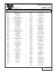
1997-2001 Ford 4.6L 2V F-150/F-250/Expedition/Navigator Part No. 4FM218-010S/018S ® PARTS LIST ENGINEERING, LLC IMPORTANT: Before beginning installation, verify that all parts are included in the kit. Report any shortages or damaged parts immediately. Part Number Description Quantity Part Number Description Quantity 2E228-160 2E128-230 2A036-361 7U100-070 2A040-011 7B375-125 7K375-040 SUPERCHARGER ASSEMBLY V-2 Supercharger 3.
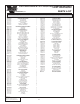
1997-2001 Ford 5.4L 2V F-150/F-250/Expedition/Navigator Part No. 4FM218-020/028S ® PARTS LIST ENGINEERING, LLC IMPORTANT: Before beginning installation, verify that all parts are included in the kit. Report any shortages or damaged parts immediately. Part Number Description Quantity Part Number Description Quantity 2E228-170 2E128-220 2A038-333 7U100-070 2A040-011 7B375-125 7K375-040 SUPERCHARGER ASSEMBLY V-2 Supercharger 3.
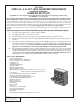
1. COMPONENT REMOVAL AND PREPARATION A. Disconnect the negative battery cable. NOTE: 1999-2003 Models Only 1. Remove the passenger side front kick panel from the interior of the vehicle. Remove the sound deadening material (if any) that is covering the ECM. Remove the plastic ECM hold-down bracket. 2. From the engine side of the firewall (in the engine compartment), use a 10mm socket or wrench and remove the harness and plug from the ECM (as you loosen the bolt, the connector will slowly release).
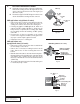
2. OIL FEED LINE INSTALLATION A. B. Unplug the connector on the oil pressure sending unit. Remove the sending unit from the engine block. (The unit is located on the left front side of the engine, just above the oil pan.) Thread the supplied 1/4" NPT fittings into the block as shown. Reinstall the sending unit and connector.
2. OIL FEED LINE INSTALLATION, cont'd. • Using a light amount of oil on the threads for lubrication, thread the 1/8" NPT x 45° x #4 fitting into the threaded hole. Teflon tape, paste or other sealant is not recommended as it might loosen and cause blockage of the oil feed orifice, resulting in supercharger failure. Rotate the fitting so that when it is tight, it will face the front of the vehicle. • Reassemble the oil filter base and bracket and secure onto the vehicle. Reinstall oil filter.
3. OIL DRAIN, cont'd. NOTE: This method of rolling over the lip of the hole and tapping works very well if carefully done and should cause no problem. E. Thoroughly clean the threaded area. Apply a small amount of silicone sealer to the new threads. Apply more sealer to the 3/8" NPT x 1/2" inverted flare fitting and secure in hole. Make sure a seal is formed all around the fitting. F. Thread the tube nut and 1/2" x 90° aluminum tube into the inverted flare fitting by hand.
4. CRANKSHAFT PULLEY/SUPERCHARGER DRIVE PULLEY NOTE: This process can be done with the fan shroud and radiator in place providing your balancer puller is equipped with a 5” or shorter forcing screw. Removing the fan shroud and the radiator will allow easier access to the crank pulley and the front of the engine. A. B. Remove the rubber inspection plug on the left rear of the block to make the flexplate accessible.
4. CRANKSHAFT PULLEY/SUPERCHARGER DRIVE PULLEY, cont'd. E. F. 5. Remove the installation tool and place the supercharger drive pulley on the front of the harmonic balancer. Feeling for alignment, start the 12mm x 1.50 x 65mm center bolt with thick factory washer and rotate the supercharger drive pulley until the three bolt holes are aligned. Start the three 8mm x 1.
6. FUEL PUMP RELAY A. Remove the power distribution box from its mounting bracket. Remove the bottom cover and the side panel exposing the main power lugs, the bottom of the fuses and relays. B. Looking at the underside of the power distribution box, locate the fuel pump relay (should be labeled #4). Directly beneath the fuel pump relay, locate the green wire with yellow stripe. C.
7. WIRE PREPARATION (4.6 models only) A. To accommodate the installation of the supercharger and the relocation of the coil, it will be necessary to modify the coil and cam trigger loom, extend the radio ignition interference wire and relocate the spark plug wire clips. B. Remove the 90° plastic wire support from the cam sensor plug, this will allow the wire to be routed tightly against the face of the main mounting plate at a later time. C.
8A. MAIN MOUNTING PLATE ASSEMBLY AND MOUNTING (4.6L models only) A. Attach the supplied power steering reservoir/coil bracket to the main mounting plate using the 1/4-20 x 3/4” bolts, nuts and washers (see photo). B. Using the supplied 10-24 x 2” bolts and washers, secure the coil and the radio ignition interference capacitor to the power steering reservoir/coil bracket. C.
8A. MAIN MOUNTING PLATE ASSEMBLY AND MOUNTING (4.6L models only) cont'd. I. J. K. Move the power steering reservoir into the appropriate location on the new power steering reservoir/coil mounting bracket and secure with the provided 1/4" hardware. Secure the power steering reservoir lines away from the steering shaft with the tie wraps provided. Reattach the plug wires to the coil and secure with the previously removed clips. Fig. 8A-d 8B. MAIN MOUNTING BRACKET ASSEMBLY AND MOUNTING (5.
8B. MAIN MOUNTING BRACKET ASSEMBLY AND MOUNTING (5.4L models only), cont'd. H. Install the supplied support strap between the back of the main mounting bracket and the boss on top of the thermostat housing. Secure both ends using the supplied 6mm bolt and washer and the 1/4-20 x 1" flat allen bolt, washer and lock nut. I. Attach the supplied power steering reservoir bracket to the main mounting bracket using the 1/4-20 bolt and washers (see photo). J.
9. EGR CONTROL MOUNTING AND MAIN MOUNTING PLATE SUPPORT (4.6L models only) A. Using the #10-24 x 1/2” bolts, nuts and washers, remount the EGR controls onto the Vortech mounting bracket. B. Directly beneath the EGR bracket, locate the 6mm bolt securing the fuel rail. Remove the bolt. C. Install the supplied support strap between the intake manifold and the main mounting plate. Secure both ends using the factory 6mm fuel rail bolt and the supplied 3/8-16 x 1" hexhead bolt, nut and washer.
FACTORY VACUUM CONNECTION FUEL MANAGEMENT UNIT (FMU) VACUUM LINE FACTORY SPRINGLOCK CONNECTOR FACTORY REGULATOR INLET OUTLET FUEL RETURN LINE ENGINE FACTORY QUICKDISCONNECT FITTING FUEL FEED LINE F. heat with the provided tie wraps. Tap into the factory fuel regulator vacuum line with the supplied 5/32" hose and TEE. Route the new hose to the fitting on top of the FMU (see drawing). FILTER T-REX FUEL TANK Fig. 10-b 10.1 FUEL MANAGEMENT UNIT RECALIBRATION (2003 5.4L Only) A.
11. IDLE AIR CONTROL RESONATOR AND CRANKCASE VENT HOSE REROUTING * A. Attach the supplied 3/4” x 90° rubber elbow to the B. C. idle control motor near the throttle body. (See Fig. 11-a.) Insert the factory idle control resonator into the elbow and locate underneath the discharge tube. Connect the supplied 3/4” x 28" hose to the idle control resonator and route the remaining end to the new air inlet location. See step 14.
12. SUPERCHARGER MOUNTING, cont'd. G. Secure the oil feed line and oil drain line away from heat and abrasion with the provided tie wraps. *H. Mount the belt tensioner plate onto the face of the supercharger with the three 12mm x 1.75 x 20mm bolts and washers. The thin head bolt must be installed nearest the idler pulley pilot. 5.4L ONLY - Mount the automatic tensioner to the mounting bracket using the 3/8-16 x 3.25" bolt and washer. I.
12. SUPERCHARGER MOUNTING, cont'd. 5.4L MODELS ONLY SPRING TENSIONER RIBBED IDLERS SMOOTH IDLER HARMONIC BALANCER/ CRANK PULLEY Fig. 12-d P/N: 4FM020-010 © 2003 Vortech Engineering, LLC All Rights Reserved. Intl. Copr. Secured 20OCT03 v3.1 4.6/5.4Exped/Nav(4FM v3.
13. MASS AIR FLOW SENSOR REMOVAL, MOUNTING AND ASSEMBLY A. Separate the mass air flow sensor from the air inlet canister. B. Assemble the mass air sensor and the mass air sensor mounting bracket with the 1/4-20 x 3/4" bolts, nuts and washers. Mount the air filter to the bracket and secure the #60 clamp. C.
14. AIR INLET/BYPASS ASSEMBLY, cont'd. C. Install the bypass valve and #16 hose clamp on the end of the 1" x 5" hose - 4.6L, 1" x 9" hose - 5.4L. On the 4.6L, bypass nipple should be pointing toward the driver's seat. On the 5.4L, bypass nipple should be pointing downward. D. Using the supplied 5/32" TEE and hose, splice the bypass nipple into the previously installed vacuum hose attached to the FMU lid. E. Place the 1" x 7"-4.6L, 1" x 2.5" - 5.4L piece of hose and #16 hose clamps on the bypass valve.
15. DISCHARGE A. Install the 3” silicone sleeve and the #48 hose clamps on the throttle body. B. Slide the 2-3/4” silicone sleeve and the #44 hose clamps onto the discharge tube. C. Install the discharge tube on the throttle body side. Rotate the supercharger side into position and center the silicone sleeve. Secure with #48 and #44 hose clamps. D. Connect the 1” bypass hose to the bung on the backside of the discharge tube and secure using a #16 hose clamp. E.
® ENGINEERING, LLC 1650 PACIFIC AVENUE • CHANNEL ISLANDS, CA 93033-9901 • (805) 247-0226 FAX (805) 247-0669 • www.vortechsuperchargers.com • M-F 8:00 AM - 4:30 PM PST P/N: 4FM020-010 © 2003 Vortech Engineering, LLC All Rights Reserved. Intl. Copr. Secured 20OCT03 v3.1 4.6/5.4Exped/Nav(4FM v3.