FCSD Technical Training INTERACTIVE STUDY GUIDE 2005 EXPEDITION/NAVIGATOR NEW MODEL TECHNICIAN TRAINING FCS-14000-DL 2005 EXPEDITION/NAVIGATOR NEW MODEL TECHNICIAN TRAINING 02-SEP-04 COURSE CODE: 30N29F0
IMPORTANT SAFETY NOTICE Appropriate service methods and proper repair procedures are essential for the safe, reliable operation of all motor vehicles, as well as the personal safety of the individual doing the work. This manual provides general directions for accomplishing service and repair work with tested, effective techniques. Following them will help assure reliability.
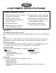
CUSTOMER EXPECTATIONS Customer Expectations: Service 1. Make it convenient to have my vehicle serviced at your dealership. 2. The Service Advisor should demonstrate a genuine concern for my service needs. 3. Fix it right the first time. 4. Complete servicing my vehicle in a 5. Provide me with a clear and thorough explanation of the service performed. 6. Call me within a reasonable amount of time after my service visit to ensure that I’m completely satisfied. 7.
TABLE OF CONTENTS INTRODUCTION ............................................................................................................... Intro-1 Technical Training ........................................................................................................ Intro-1 Ground Rules for Successful Completion .................................................................... Intro-1 Logging On ......................................................................................................
TABLE OF CONTENTS NOTES ii 02-SEP-04 2005 Expedition/Navigator New Model Technician Training
INTRODUCTION FCSD Technical Training The distance learning course you are about to take is intended to give you new knowledge and information about diagnosing and servicing Ford and Lincoln/Mercury vehicles. We hope you will apply this knowledge and information to ‘‘Fix It Right The First Time’’ as part of the effort to satisfy our customer, the owners of Ford and Lincoln/Mercury products. Ground Rules for Successful Completion This course is what we call ‘‘score based.
INTRODUCTION LOGGING ON Your response keypad transmits data and voice between you and the host site via telephone lines and satellite. It is your ‘‘lifeline,’’ connecting you to the instructor as well as to other participants. Using the keypad, you can become fully involved in the seminar, asking questions and contributing relevant comments. To log on at the beginning of the broadcast session: 1. Enter your Social Security number (in response to the keypad prompt).
INTRODUCTION KEYPAD OPERATION CALL Key • Press the CALL key if you have a question or comment. This places you in the call queue. The system indicates your name and location to the instructor. • It takes approximately 60 seconds for the instructor to respond. If you change your mind about asking the question, simply press the CALL key again. As long as the instructor has not accepted your call, this takes you out of the call queue.
INTRODUCTION IN-DEALERSHIP TRAINING MAP Intro-4 02-SEP-04 2005 Expedition/Navigator New Model Technician Training
INTRODUCTION PURPOSE The purpose of this FORDSTAR course is to provide Ford and Lincoln/Mercury service technicians with the knowledge needed to understand new systems, new or updated components and unique diagnostic and service procedures for the 2005 Expedition/Navigator.
INTRODUCTION NOTES Intro-6 02-SEP-04 2005 Expedition/Navigator New Model Technician Training
LESSON 1: OVERVIEW OBJECTIVES • Identify the new powertrain applications for Expedition and Navigator. • Identify exterior features. • Identify interior features. • Identify lifting and jacking points. • Identify maintenance check points.
LESSON 1: OVERVIEW Mechanical and Chassis Features Mechanical and Chassis Features • 5.4L 3-Valve Triton Engine w/Variable Cam Timing. • 6HP26 Automatic Transmission (Navigator only). • 4R75E Automatic Transmission (Expedition only).
LESSON 1: OVERVIEW Engine - 5.4L 5.4L 3-Valve Triton Phaser The 2005 Expedition and Navigator are available with one engine: • New for 2005, the 5.4L 3-valve Triton V8. – 300 horsepower @ 5,000 rpm – 365 lb-ft of torque @ 3,750 rpm – Variable cam timing – Three valves per cylinder – Electronic Throttle Control (ETC) Rather than focusing on a single item to gain improvements in power, Ford used an approach that included advancements on multiple fronts.
LESSON 1: OVERVIEW • Variable Cam Timing (VCT) varies cam timing to match performance demands. • Charge Motion Control Valves (CMCV) manage the flow of air into the cylinders. • Vibration-resistant ribbing and reinforcement in the lower engine block help manage and tune sound and vibration. – The engine block ribbing strengthens the block wall similar to cross reinforcements in a building wall.
LESSON 1: OVERVIEW Automatic Transmission 6HP26 Transmission The 2005 Expedition will use the 4R75E automatic transmission like the 2004 and 2005 F-150, while the Navigator uses the all-new 6HP26 automatic. The 6HP26 6-speed transmission uses total electronic control for all functions. The Transmission Control Module (TCM) and the main control valve body units are combined and installed as a single unit inside the automatic transmission.
LESSON 1: OVERVIEW Exterior Features 2005 Navigator Exterior • New body side cladding – Bold new body side cladding is added to the 2005 Lincoln Navigator. The cladding is painted body color and enhances as well as protects the exterior appearance. • New front fascia – An agressive front fascia is standard on the Lincoln Navigator and comes with integral fog lamps and front spoiler. High Intensity Discharge (HID) headlamps are optional on all models.
LESSON 1: OVERVIEW 2005 Expedition Exterior • New badging for Limited and FX4 (mid 4th quarter availability). – Expedition for 2005 comes with new badging when equipped with the Limited and FX4 packages. • New power fold side view mirrors. – Expedition Limited for 2005 comes with new power fold side view mirrors. The mirrors are controlled by a switch that is integral with the power mirror switch.
LESSON 1: OVERVIEW Interior Features 2005 Navigator Interior • New 6HP26 automatic transmission gear selector. – Lincoln Navigators are equipped with a new 6HP26 transmission. The gear selector allows for manual or automatic selection of first through fourth gear (O/D disabled) and first through sixth (O/D enabled). O/D is enabled by moving the gear selector handle to the left while in the D6/D4 gate and is disabled by moving it to the right.
LESSON 1: OVERVIEW 2005 Expedition Interior The 2005 Expedition receives minor trim and finish updates as: • Power fold side view miror switch (Limited only). – The power fold mirrors are operated from a switch that is integral with the power mirror switch. – In contrast to the power folding mirror switch already available in the Navigator, to retract or extend the folding mirrors, rotate the mirror adjustment knob to the center position. Pressing the switch down one time will fold the mirrors inward.
LESSON 1: OVERVIEW Lifting and Jacking Lifting and Jacking Points The front and rear lifting and jacking locations are as indicated.
LESSON 1: OVERVIEW Maintenance Check Points Maintenance Check Points (Navigator Shown) Item Description Item Description 1 Cabin Air Filter 6 Engine Coolant 2 Engine Air Filter 7 Engine Oil Fill 3 Power Steering Fluid 8 Windshield Washer Solvent 4 Engine Oil Dipstick 9 Battery 5 Brake Fluid All maintenance point locations are carry-over from 2004 with the exception of the transmission fluid (on Lincoln Navigator) and air filter element (on both).
LESSON 1: OVERVIEW NOTES 1-12 02-SEP-04 2005 Expedition/Navigator New Model Technician Training
LESSON 2: CHASSIS OBJECTIVES • Identify changes to the TPMS. • Identify new suspension system features. • Identify new drive axle/differential driveline features.
LESSON 2: CHASSIS Wheels and Tires Tire Pressure Monitor • TPMS functionality is integrated into Vehicle Security Module (VSM) located in the right kick panel. • Communicates with sensor at 315 MHz. • Blue colored sensor (315 MHz), unique for 2005 Expedition and Navigator. • Sensor Training process is same as previous TPM system (with exception of spare tire). • 2004 sensor (Black, 433 MHz) will NOT work on 2005 Expedition or Navigator.
LESSON 2: CHASSIS TPMS General Information Temperature fluctuation changes tire inflation pressure 7KPa per 12 degrees Celsius (1 psi per 10 degrees F) Article #: SSM 17496 Date: 01/16/2004: TPMS SYSTEM-DO NOT USE AFTERMARKET WHEELS. SOME 2003-2004 EXPEDITION/NAVIGATOR/AVIATOR/EXPLORER/MOUNTAINEER VEHICLES MAY EXHIBIT A TIRE PRESSURE MONITORING SYSTEM (TPMS) WARNING, OR OTHER RELATED CONDITIONS, IF AFTERMARKET WHEELS ARE INSTALLED.
LESSON 2: CHASSIS Functionality - 2005 Model Year Sensor Wheel Package Item 1 Description Item Description Blue, 315 Mhz Tire Pressure Sensor • 4-sensor system (road tires only, does not include spare). • RF-based. – Sensors transmit pressure and unique ID to VSM (integrated system). – Receiver (TPM integral to VSM) receives information, processes information, and communicates status to the cluster via MS-CAN link. • TPMS warnings displayed on message center (if equipped).
LESSON 2: CHASSIS Sensor Description TPMS Sensor Item Description Item Description 1 Transmitter Case 5 Aluminum Valve 2 Air Hole: Top 6 Inside: Core 3 Potted Surface: Bottom 7 Nut 4 Grommet 8 Cap • 315 MHz (Blue), Manchester Encoded, AM. • Pressure Sampling / Transmission. – Stationary – 15 minute sample /1 hour transmission. – Rolling – 30 second sample/1 minute transmission. • Motion switch sampling rate – 10 second. • Full Scale Pressure Range: 0 – 64 psi.
LESSON 2: CHASSIS Module Description • TPM System integrated into Vehicle Security Module (VSM). • Module designed to: – Receive tire pressure and sensor information (315MHz transmissions from sensors). – Process input information, determine correct status, and associate sensors with module (learn). – Communicate status to message center via MS-CAN. – Output to horn relay (self test and manual learn mode).
LESSON 2: CHASSIS Cluster Messages The following are messages that can be displayed on the message center (if equipped on Expedition models, standard on Navigator).
LESSON 2: CHASSIS DTCs 2-8 DTC Description B1342 ECU Defective B2477 Module Configuration Failure B2868 Left Front Sensor Fault B2869 Right Front Sensor Fault B2870 Right Rear Sensor Fault B2871 Left Rear Sensor Fault B2872 Tire Sensor Fault B1217 Horn Relay Circuit Failure C2780 ECU in Manufacturing Mode 02-SEP-04 2005 Expedition/Navigator New Model Technician Training
LESSON 2: CHASSIS TPMS PIDs NGS Name WDS Name Description LF_ID LF_ID_VSM LEFT FRONT TIRE SENSOR ID RF_ID RF_ID_VSM RIGHT FRONT TIRE SENSOR ID RR_ID RR_ID_VSM RIGHT REAR TIRE SENSOR ID LR_ID LR_ID_VSM LEFT REAR TIRE SENSOR ID LF_PRES LF_PSI_VSM BP COMPENSATED PRESSURE CALCULATED BY MODULE (BARO COMP VALUE) RF_PRES RF_PSI_VSM BP COMPENSATED PRESSURE CALCULATED BY MODULE (BARO COMP VALUE) RR_PRES RRO_PSI_VSM BP COMPENSATED PRESSURE CALCULATED BY MODULE (BARO COMP VALUE) LR_PRES LRO_P
LESSON 2: CHASSIS Possible Failure Modes and Root Causes • TPMS indicator light stays ON continuously. Message center (if equipped) Displays: ‘‘Low Tire Pressure’’. – Causes: 1. Air pressure is low or not set to required placard pressure. 2. Spare tire currently in use. – Solution: • 1. Check tire pressure with digital gauge. If issue still persists, then retrieve DTC and follow pin point test F2 described in service manual. 2. Repair original tire and install road wheel/tire.
LESSON 2: CHASSIS Driveshaft Driveshaft • Navigator 4x2 models use a unique 2-piece driveshaft. • Staked U-Joint Service. – The original u-joints are staked in place. There is no retaining clip. – The factory u-joints require the use of a special cutting tool to remove the stakes prior to the removal of the u-joint cups. After appropriately mounting the driveshaft in a vise, the cutting tool (which is part of the u-joint replacement kit) is rotated by using a ratchet handle to remove the stakes.
LESSON 2: CHASSIS Front Drive Axle/Differential Front Drive Axle/Differential • New companion flange – The design of the front axle companion flange is unique to the 2005 Expedition and Navigator. When servicing, be sure to obtain the proper parts for your specific application.
LESSON 3: POWERTRAIN OBJECTIVES • Identify new 5.4L 3-valve engine features. • Explain the operation of the VCT system. • Explain the revised procedure for camshaft or phaser assembly replacement. • Identify 6HP26 automatic transmission features. • Explain the basic functions of the 6HP26 transmission controls. • Explain the basic shift control strategies of the 6HP26 transmission.
LESSON 3: POWERTRAIN Engine - 5.4L 5.4L 3-Valve Triton Phaser The 2005 Expedition and Navigator are available with one engine: • New for 2005, the 5.4L 3-valve Triton V8. – 300 horsepower @ 5,000 rpm – 365 lb-ft of torque @ 3,750 rpm – Variable cam timing – Three valves per cylinder Rather than focusing on a single item to gain improvements in power, Ford used an approach that included advancements on multiple fronts.
LESSON 3: POWERTRAIN • Charge Motion Control Valves (CMCV) manage the flow of air into the cylinders. • Vibration-resistant ribbing and reinforcement in the lower engine block help manage and tune sound and vibration. – The engine block ribbing strengthens the block wall similar to cross reinforcements in a building wall.
LESSON 3: POWERTRAIN 5.4L Three-Valve Head The three-valve head has two smaller intake valves and one larger exhaust valve. • The three-valve head includes all of the advantages of the four-valve head with fewer parts and less noise. CAUTION: Remove the spark plugs before removing the heads. The spark plugs are long and can be damaged if left in the head. The gap is non-adjustable. The spark plugs used in the 3-valve head require a special 9/16 inch socket.
LESSON 3: POWERTRAIN Air Filter Intake Air Filter Module (IAFM) The intake air distribution and filtering design has been replaced with: • New split line welded Intake Air Filter Module (IAFM). The IAFM is a one piece, plastic component that houses the air filter element and Mass Air Flow (MAF) sensor. CAUTION: When removing the air inlet tube from the IAFM, be sure to disengage the retaining tab at the top of the tube.
LESSON 3: POWERTRAIN Mass Air Flow (MAF) Sensor The compact Mass Air Flow (MAF) sensor is located on the IAFM. • This sensor combines the Intake Air Temperature (IAT) and the MAF sensor.
LESSON 3: POWERTRAIN Electronic Throttle Control (ETC) ETC Throttle Body • The 5.4L 3V engine used in both the Expedition and Navigator utilizes Electronic Throttle Control (ETC). This system functions and is serviced similarly to the systems used on the Thunderbird and LS. Warning indications are via an instrument cluster mounted message center or warning light. This is covered in greater detail in Lesson 4. Refer to the Work Shop Manual for additional information on ETC service and diagnostics.
LESSON 3: POWERTRAIN Charge Motion Control Valves (CMCV) The Charge Motion Control Valves (CMCV) are electronically controlled metal flaps at the end of each intake runner, eight in total (four per bank on one rod, operated together). • CMCVs work to speed up the intake air charge and induce a ‘‘tumble’’ effect into the combustion chamber at low engine speeds and loads. – Causes a thorough mix of the air/fuel charge. – Results in a quick, efficient burn which helps reduce emissions.
LESSON 3: POWERTRAIN CMCV Motor The CMCVs use one electronically controlled motor to operate the CMCVs for both sides of the intake manifold.
LESSON 3: POWERTRAIN CMCV Block Diagram The CMCVs are controlled electronically by the PCM. • The inputs used by the PCM for the CMCV operation are: – Engine Speed – Throttle Position – Air Temperature – Cylinder Head Temperature • The CMCV system does not use a feedback loop. • The CMCVs open at a predetermined engine speed. – At higher RPM, they do not affect the intake air charge. – Proper stoichiometric air/fuel ratio (14.7:1) is easiest to achieve when the intake air is moving quickly.
LESSON 3: POWERTRAIN VCT System 5.4L Variable Cam Timing Solenoid Electrical Connector Conventional camshafts are permanently synchronized with the engine crankshaft to operate the intake and exhaust valves at a specific point in each combustion cycle. Variable Cam Timing (VCT), however, allows the valves to operate at variable points in the combustion cycle. • The VCT system on the 5.4L provides several important benefits: – Eliminates the need for an EGR system.
LESSON 3: POWERTRAIN VCT Operation VCT The theory of operation for the 5.4L VCT is similar to the 3.9L VCT used on the Lincoln LS and 2004 Ford F-150 w/5.4L. • The major differences are: – The 5.4L VCT system controls both intake and exhaust valve timing because the 3-valve setup uses one camshaft for both intake and exhaust valves. – On the 3.9L, the VCT only controls the intake camshafts. – Parts look different and are serviced differently (5.4L vs. 3.9L).
LESSON 3: POWERTRAIN The basics of VCT operation are: • A hydraulic timing mechanism (VCT phaser) rotates the camshafts in relation to their drive sprockets. – Provides performance that is precisely tailored to the engine speed and load. – VCT is electronically controlled (PCM duty cycled) and hydraulically operated. • The VCT solenoid moves a spool valve to control the flow of oil through the VCT system. – Oil flows from the head into the VCT valve body.
LESSON 3: POWERTRAIN 5.4L 3-Valve Camshaft Position Sensor The VCT system requires a cam position sensor for each camshaft. • The PCM can then monitor the actual camshaft position relative to the requested position.
LESSON 3: POWERTRAIN Oil Temperature Sensor The VCT system uses a replaceable oil temperature sensor, located on the oil pan. • Engine oil temperature has a direct effect on VCT operation. – Cold engine oil has high viscosity and slower flow characteristics. – The VCT system is disabled at oil temperatures below -7°C (18°F). – The PCM uses time-since-start, engine oil temperature and engine rpm to calculate VCT solenoid operation.
LESSON 3: POWERTRAIN Phaser Components VCT Phaser The VCT components include: • Camshaft phaser sprockets. • Right and left camshaft phaser sprocket assembly bolt and washer. • VCT valve bodies (housing). • VCT solenoids. • Right and left camshafts. NOTE: The phaser, phaser sprocket, vanes and the return spring are serviced as an assembly.
LESSON 3: POWERTRAIN Phaser Oil Vanes The oil vanes create oil cavities for valve-directed oil to rotate the camshaft in relation to the crankshaft. • Oil pushes on one side of the vanes to rotate the cam in one direction to advance timing. • Oil pushes on the other side of the vane to rotate the cam in the other direction to retard timing.
LESSON 3: POWERTRAIN VCT Phaser Disassembled The VCT phaser varies camshaft timing in response to oil pressure exerted on either side of the vanes. CAUTION: Only use hand tools to remove the camshaft phaser sprocket assembly or damage may occur to the camshaft or camshaft phaser unit. CAUTION: Always install a new bolt and washer whenever the VCT phasers are loosened. The base part number is 6279. The same part number is used for both sides.
LESSON 3: POWERTRAIN VCT Solenoid Removal The VCT solenoid is serviced separately from the VCT valve body. No special tools are needed to remove the solenoid. The retaining bolt is captured in the mounting tab. 1. Disconnect the solenoid electrical connection. 2. Remove the valve cover grommet. 3. Remove the hold-down bolt. 4. Remove the solenoid. CAUTION: Do not drop the solenoid screw into the front cover.
LESSON 3: POWERTRAIN VCT Valve Body Oil Passages Item Description Item Description 1 Solenoid filter 5 Oil passage back into head 2 Oil passage to advance side of VCT 6 Oil metering orifice 3 Oil passage to retard side of VCT 7 Oil passage from head 4 Oil passage to chain tensioner The valve body and solenoid work together to route oil to the vanes in the camshaft phaser to operate the VCT system. NOTE: The solenoid filter is not removable or serviceable and is located in the valve body.
LESSON 3: POWERTRAIN Locking Pin The locking pin locks the camshaft in a fully advanced position when the engine is off. • The pin locks the phaser to the camshaft during startup. • After startup, oil pressure at the VCT assembly will unlock this pin, allowing VCT operation to resume. – Makes it easier to start engine. – Reduces noise on startup. • VCT does not control valve timing until the oil temperature reaches 32°F (0°C).
LESSON 3: POWERTRAIN Phaser/Camshaft Removal Procedure Remove Valve Cover The phaser replacement procedure has been revised for the 5.4L 3V engine. This revision allows for the servicing of either the left or right phaser or camshaft without having to remove the engine front cover. Remove the left and/or right valve cover(s).
LESSON 3: POWERTRAIN Set Crankshaft Damper Notch to 1 o’clock Position Set the crankshaft keyway to 12 o’clock. The machined notch on the back face of the damper pulley should appear at about the 1 o’clock position. NOTE: The number one piston should have just passed TDC when the crank was turned the normal rotational direction of engine operation.
LESSON 3: POWERTRAIN Cam Lobe Positioning Item 1 Description Item Intake Lobe 2 Description Exhaust Lobe Pointing Inward The camshaft must be positioned with the #1 or #8 exhaust lobe facing inward to the 3 o’clock position. • If the lobes are not positioned this way, the crankshaft will require one full additional rotation to 12 o’clock.
LESSON 3: POWERTRAIN Mark Crankshaft Damper The damper spoke pointing upwards just to the left of the machined notch is the one with the keyway cut in it. Chalk mark that spoke for easy viewing.
LESSON 3: POWERTRAIN Loosen One Turn Loosen the camshaft phaser bolt one turn. Do not remove the bolt. CAUTION: DO NOT use an impact wrench when loosening the phaser bolt. Impact tools can damage internal phaser components.
LESSON 3: POWERTRAIN Remove Only the Indicated Followers When removing the followers, remove the exhaust followers from the exhaust manifold side of the camshaft and the intake followers from the intake side.
LESSON 3: POWERTRAIN Set Crankshaft Damper Spoke to 6 o’clock Position Rotate the marked damper spoke clockwise to the 6 o’clock position. CAUTION: It is imperative that the engine is only rotated to the 6 o’clock position in a clockwise rotation. NOTE: The only time the engine is turned counter-clockwise back to the 12 o’clock keyway position is during the re-assembly procedure.
LESSON 3: POWERTRAIN Inset Timing Chain Wedge Tool Assemble the ESST 303-636 Timing Chain Wedge to the ESST 303-637 Handle. Insert the timing chain wedge tool between the chain spans. Four to six clicks will hold it. Mark the chain to the phaser for reinstallation. The ‘‘R’’ on the right phaser (and the ‘‘L’’ on the left) that was used on the 2004 F-150 is no longer used.
LESSON 3: POWERTRAIN Loosen #1 Camshaft Bearing Cap Bolts Mark the cam caps for proper reinstallation. NOTE: The camshaft bearing caps must be installed in their original locations. Record camshaft bearing cap locations. Loosen the camshaft bearing caps. Start with the #1 cap because it contains a thrust surface groove. If the cam were to be moved in some fashion with this cap intact, the cap could be damaged or broken. Remove the remaining cap bolts according to Workshop Manual procedures.
LESSON 3: POWERTRAIN Remove the Phaser Bolt The remaining followers will be loose on the lifters. Be sure to keep them in place so that the camshaft can be reinstalled. Remove the CMP sensor. Fully withdraw the camshaft sprocket phaser bolt by hand.
LESSON 3: POWERTRAIN Remove the Phaser Using extreme care, withdraw the phaser from the nose of the camshaft. It may be necessary to slightly tip up the cam from the rear to allow chain disengagement. CAUTION: Do not let the camshaft set in the cylinder head unattended. The cam may fall out.
LESSON 3: POWERTRAIN Cam and Phaser Reassembly Seating Cam Followers Care should be taken to ensure that the remaining followers are properly seated prior to camshaft installation.
LESSON 3: POWERTRAIN Phaser Pin and Cam Notch Item 1 Description Item Phaser Pin 2 Description Cam Notch It is extremely important to align the phaser pin with the camshaft end notch. NOTE: If these are not aligned during installation, the phaser and camshaft will be damaged.
LESSON 3: POWERTRAIN Installing the Bearing Caps Install the camshaft bearing caps in the reverse order of removal. NOTE: The camshaft bearing caps must be installed in their original locations. The front thrust cap should be installed last to prevent the cap from breaking. Next, install the phaser bolt by hand. Remove the timing chain wedge. Rotate the crankshaft pulley counter-clockwise back to the 12 o’clock position. NOTE: Tighten the phaser bolt to 40 Nm (30 lb-ft), plus 90 degrees.
LESSON 3: POWERTRAIN Electronic Engine Controls Electronic Engine Controls • New integrated 4x4 strategy. – 4x4 operational strategy is now incorporated into the PCM. This eliminates the need for a separate module to control the transfer case. • The PCM utilizes a 190 pin connector. • New PCM controlled, electronically heated PCV port.
LESSON 3: POWERTRAIN • New premium fuel calibration (Navigator). – The aggressive spark and fuel programming requires 91 octane (or higher) fuel for maximum performance. Expedition requires 87 octane fuel for optimal performance. NOTE: Refer to the Workshop Manual for diagnostic and service procedures for these items.
LESSON 3: POWERTRAIN Fuel Tank and Lines Fuel Tank and Lines • New fuel filter – The fuel filter is located on the front side of the fuel tank. It can be accessed by removing the road debris shield. Quick connect fittings are used for connection to the fuel lines. • The fuel tank sending unit tool (SST310-123) is required to service the fuel pump and/or sending unit. This tool was released as part of the 2004 F-150 tool kit.
LESSON 3: POWERTRAIN Engine Special Service Tools Engine Special Service Tools Item Description Item Description 1 ESST 307-516/1 Installer, Teflon Seal (4R75E Tool) 7 ESST 310-123 Remover/Installer Tank Sender Unit 2 ESST 307-516/2 Installer, Teflon Seal (4R75E Tool) 8 ESST 205-086-1 Adaptor for 205-086 3 ESST 307-516/3 Installer, Teflon Seal (4R75E Tool) 9 ESST 418-F395 Diagnostic Service Tool, Restraint System 4 ESST 307-516/4 Installer, Teflon Seal (4R75E Tool) 10 ESST 303-1046 Locki
LESSON 3: POWERTRAIN Automatic Transmission Description 6HP26 Transmission The 6HP26 transmission uses planetary gears with multiple clutches and electronic controls. The Transmission Control Module (TCM) and the main control valve body units are combined and installed as a single unit inside the automatic transmission. This transmission has the following features: • six forward speeds. • a torque converter with an integral converter clutch. • electronic shift and pressure controls.
LESSON 3: POWERTRAIN • shift feel. • shift scheduling. • modulated Torque Converter Clutch (TCC) applications. • engine braking. This transmission has a mechatronic unit (valve body) which contains: • Turbine Shaft Speed (TSS) sensor. • Output Shaft Speed (OSS) sensor. • An internal P, R, N, D6, D4, 3, 2, 1 selector shaft position sensor. • Transmission Fluid Temperature (TFT) sensor.
LESSON 3: POWERTRAIN Operation 6HP26 Cutaway Engine power reaches the transmission by a torque converter with an integral converter clutch. The six forward gears and one reverse gear are obtained from both single and double planetary sets. This automatic transmission is a six-speed electronically controlled transmission comprised of a TCM, main control valve body unit, torque converter, one solenoid valve and six pressure regulators.
LESSON 3: POWERTRAIN Identification Tag Identification Tag The identification tag is located on the left side of the case just rearward of the manual control lever.
LESSON 3: POWERTRAIN Range Selection Shifter Pattern The transmission has eight range positions: P, R, N, D6, D4, 3, 2 and 1.
LESSON 3: POWERTRAIN The D6 position is the normal position for most driving conditions.
LESSON 3: POWERTRAIN Shift Patterns • Under certain conditions the transmission automatically downshifts to a lower gear range (without moving the range selector lever). There are three categories of automatic downshifts: – coastdown – torque demand – forced or kickdown shifts • Coastdown The coastdown downshift occurs when the vehicle is coasting to a stop.
LESSON 3: POWERTRAIN Shift Elements Shift Elements Item Description Item Description 1 Double Planetary Gearset 6 Overdrive Clutch 2 Forward Clutch 7 Low/Reverse Clutch 3 Transmission Case (Fixed) 8 Single Planetary Gearset 4 Direct Clutch 9 Stator Shaft 5 Intermediate Clutch 10 Turbine Shaft The shift elements are: – Three rotating multi-plate clutches: forward, direct and overdrive. – Two fixed multi-disc clutches: intermediate and overdrive.
LESSON 3: POWERTRAIN The shift elements are engaged hydraulically. The transmission fluid pressure builds up between the cylinder and the piston, pressing the clutches together. The purpose of these shift elements is to carry out in-load shifts with no interruption to traction. Multi-plate clutches forward, direct and overdrive supply power from the engine to the planetary gear train.
LESSON 3: POWERTRAIN Multi Plate Clutch Multi Plate Clutch Item Description Item Description 1 Clutch Pack Cluster 6 Turbine Shaft 2 Piston 7 Lubricating Oil Passage 3 Cylinder 8 Cup Spring 4 Ring Gear (Planetary Gearset 1) 9 Baffle Plate 5 Main Pressure Supply to Clutch 10 Inner Plate Carrier Multi plate clutches are used exclusively throughout the 6HP26 transmission. No bands are used.
LESSON 3: POWERTRAIN Fluid Pan, Gasket and Filter Fluid Pan, Gasket and Filter The transmission fluid pan, gasket and filter is a one-piece assembly. All transmission fluid is drawn from the transmission fluid pan by the fluid pump and passes through the filter. To drain and fill the 6HP26 transmission, perform the following steps: Drain With the vehicle in NEUTRAL, position it on a hoist. 1. Remove the fluid pan drain plug and allow the fluid to drain. 2.
LESSON 3: POWERTRAIN 5. Start the engine. Move the transmission range selector lever through all the gear ranges, checking for engagements. 6. With the engine idling (600-750 rpm) in PARK and the transmission temperature at 30°C-50°C (86°F-122°F), check and adjust the transmission fluid level. 7. If more fluid is needed, remove the fluid fill plug on the side of the case and fill until the fluid runs out of the bottom of the hole.
LESSON 3: POWERTRAIN Transmission Control Module (TCM) and Main Control Valve Body Transmission Control Module (TCM) and Main Control Valve Body The Main Control assembly (7A100) referred to as the mechatronic unit is made up of the following components, the TCM processor, seven control solenoids, and a typical main control assembly. The main control component houses valves and springs within the two halves (upper and lower).
LESSON 3: POWERTRAIN Transmission Electronic System The TCM receives input signals from certain transmission-related sensors and switches. The TCM uses these signals to control the following operations: • Shift timing • Line pressure (shift feel) • Torque converter clutch To accomplish this, the TCM uses six pressure control solenoids and one shift solenoid to control transmission operation.
LESSON 3: POWERTRAIN Transmission Control Module (TCM) Transmission Control Module (TCM) The TCM is mounted on top of the main control valve body. The control module has been designed to operate correctly in the environment in which the TCM is located. The TCM is activated and deactivated by the ignition supply and is connected to the transmission link harness by a 16-pin connector. The TCM monitors all TCM inputs and outputs to confirm correct system operation.
LESSON 3: POWERTRAIN Solenoids Solenoids Item Description Item Description 1 SSA (EDS1) 5 SSD (EDS4) 2 SSB (EDS2) 6 SSE (MV1) 3 SSC (EDS3) 7 TCC (EDS6) 4 PCA (EDS5) The hydraulic module contains one solenoid valve. The solenoid valve is activated by the TCM and is either open or closed. It is used to switch the position valve. There are six electronic pressure control valves, which convert an electronic current into a proportional hydraulic pressure.
LESSON 3: POWERTRAIN Controller Area Network (CAN) Interface Controller Area Network (CAN) Interface For the TCM to carry out shift point and shift quality management, a number of external signals are required. For shift point management, the TCM requires Output Shaft Speed (OSS) sensor, Accelerator Pedal Position (APP) sensor, Brake Pedal Position (BPP) switch and Transmission Range (TR) sensor. The High Speed Controller Area Network (HS-CAN) bus is used to share information between control modules.
LESSON 3: POWERTRAIN Sensors Integrated With TCM Sensors Integrated With TCM Item Description 1 Output Shaft Speed (OSS) Sensor 2 Transmission Fluid Temperature (TFT) Sensor Item 3 Description Turbine Shaft Speed (TSS) Sensor • Several sensors are located on the TCM and main control valve body unit. • The Turbine Shaft Speed (TSS) sensor is a Hall effect type sensor. • The Output Shaft Speed (OSS) sensor is a Hall effect type sensor.
LESSON 3: POWERTRAIN Transmission Range Position Sensor Transmission Range Position Sensor The TCM uses the position of this switch, housed on the TCM and main control valve body, to determine the selected gear range from the range selector lever. The sensor completes the start circuit in PARK and NEUTRAL, and the back-up lamp circuit in REVERSE. The sensor also opens/closes a set of switches that are monitored by the TCM to determine the position of the manual lever (P, R, N, D6, D4, 3, 2, 1).
LESSON 3: POWERTRAIN Transmission Operational Strategies Adaptive shift strategy is comprised of the following functions: • Shift Energy Management - Reduces or increases engine output torque during shifting. – Reduces excessive energy at the clutch pack. – Increases transmission service life. – Improves shift quality. – Used for trailer towing mode. • Pressure Modulation - This function monitors the hydraulic pressure during a shift.
LESSON 3: POWERTRAIN TCM Monitoring Functions The TCM monitors all transmission inputs and outputs to identify possible transmission failures. If a fault is detected, the TCM takes the appropriate actions to ensure the transmission enters a safe mode of operations. The PCM then sets a DTC and illuminates the Malfunction Indicator Lamp (MIL). • Voltage Supply - This function monitors the vehicle’s battery life.
LESSON 3: POWERTRAIN Monitoring The Substrate Temperature Sensor Substrate Temperature Sensor The TCM controls a number of high power solenoids and is surrounded by automatic transmission fluid. As a result, the TCM can get very hot. If the temperature of the hardware rises above a predetermined temperature, the TCM shuts down. Prior to shutting down, the TCM logs a fault code and illuminates the MIL. Following the shut down, the transmission enters a mechanical limp-home mode.
LESSON 3: POWERTRAIN Transmission Cooling Transmission Cooling • New quick connect transmission oil cooler lines. – Quick connect fittings are used at the transmission line-to-radiator cooler connections. Use ESST 307-441, Disconnect Tool, Transmission Cooler Line to disconnect lines for service. Refer to the Workshop Manual for diagnostic and service procedures.
LESSON 3: POWERTRAIN 6HP26 Transmission Special Service Tools Item Description 307-552 Direct Clutch Service Fixture 307-553 Front Pump Removal Tool 307-554 D Clutch Stack Gauge 307-555 Clutch Pack End Play Gauge 307-556 Fluid Pump 4x2 Rear Seal Installer 307-557 Case Bearing Installer 307-558 Case Second Bearing Installer 307-559 Shifter Seal Installer 307-560 4x4 Rear Seal Installer 307-562 Case Bearing Remover 2005 Expedition/Navigator New Model Technician Training 02-SEP-04 3-63
LESSON 3: POWERTRAIN NOTES 3-64 02-SEP-04 2005 Expedition/Navigator New Model Technician Training
LESSON 4: ELECTRICAL OBJECTIVES • Identify ETC warning features. • Identify climate control features. • Identify charging system features. • Identify Vehicle Security Module (VSM) features. • Identify module communication features.
LESSON 4: ELECTRICAL Climate Controlled Seats Climate Controlled Seats Control Head Item Description Item Description 1 Driver’s Side Intensity Level LEDs 3 Passenger’s Side Heating/Cooling Control Switches 2 Passenger’s Side Intensity Level LEDs 4 Driver’s Side Heating/Cooling Control Switches For 2005, the climate controlled seats utilize one control module (located under the passenger side front seat) to control both front seats.
LESSON 4: ELECTRICAL Warning Devices ETC Warning • New Electronic Throttle Control (ETC) warning message. • When an ETC system fault occurs, a message is displayed on vehicles equipped with message centers (all Navigators and Expeditions with high-line instrument clusters). • On vehicles equipped without message centers (Expeditions with the base instrument cluster), the ETC warning lamp will illuminate. • A corresponding DTC is also stored.
LESSON 4: ELECTRICAL Instrument Cluster Lighting • In 2004 the Navigator had a seperate dimming module that could be serviced seperately. For 2005, the dimming control is integrated into the instrument cluster. If there is an issue with the dimming system that is isolated to the instrument cluster, the entire instrument cluster will require replacement.
LESSON 4: ELECTRICAL Charging System Smart Charge Generator • The 2005 Expedition and Navigator are both equipped with a PCM-controlled charging system known as Smart Charge. On this system, the PCM determines the optimal charging voltage setpoint. Once the PCM has determined the optimal charging voltage for a given situation, the PCM signals the voltage regulator to control generator output. This system operates similar to the charging system used on the Crown Victoria/Grand Marquis/Town Car.
LESSON 4: ELECTRICAL Vehicle Security Module For the 2005 Expedition/Navigator, the Vehicle Security Module (VSM) strategy has been revised to allow Remote Keyless Entry (RKE) transmitter data (IDs and rolling codes) to be retrieved and programmed using diagnostic tools. It is no longer necessary to reprogram the remote transmitters when a VSM is replaced. When a VSM is replaced using the PMI procedure, remote transmitter data is now also transferred to the new module.
LESSON 4: ELECTRICAL Module Communication Network Module Communication Network The diagnostic tool connects to each network through the Data Link Connector (DLC). This makes diagnosis and testing of these systems easier by allowing one diagnostic tester to diagnose and control any module on the four networks from one connector. The DLC is located under the instrument panel between the steering column and the audio unit.
LESSON 4: ELECTRICAL Communication Protocols The 2005 Expedition and Navigator feature the following comunication protocols: • Medium Speed Controller Area Network (MS-CAN) The MS-CAN has an unshielded twisted pair cable.
APPENDIX: ESSENTIAL SPECIAL SERVICE TOOLS ESSENTIAL SPECIAL SERVICE TOOLS 2005 Expedition/Navigator New Model Technician Training 02-SEP-04 Appendix-1
APPENDIX: ESSENTIAL SPECIAL SERVICE TOOLS NOTES Appendix-2 02-SEP-04 2005 Expedition/Navigator New Model Technician Training
APPENDIX: ESSENTIAL SPECIAL SERVICE TOOLS 2005 Expedition/Navigator New Model Technician Training 02-SEP-04 Appendix-3
APPENDIX: ESSENTIAL SPECIAL SERVICE TOOLS Appendix-4 02-SEP-04 2005 Expedition/Navigator New Model Technician Training
APPENDIX: GLOSSARY OF TERMS GLOSSARY OF TERMS 2005 Expedition/Navigator New Model Technician Training 02-SEP-04 Appendix-5
APPENDIX: GLOSSARY OF TERMS NOTES Appendix-6 02-SEP-04 2005 Expedition/Navigator New Model Technician Training