Table of Contents Introduction Instrument Cluster 4 12 Warning lights and chimes Gauges Message center 12 17 19 Entertainment Systems 25 AM/FM stereo with CD/MP3 Auxiliary input jack (Line in) USB port Satellite radio information SYNC威 Climate Controls Manual heating and air conditioning Rear window defroster Lights Headlamps Turn signal control Bulb replacement Driver Controls Windshield wiper/washer control Steering wheel adjustment Power windows Mirrors Speed control Moon roof 25 33 35 38 41 4
Table of Contents Seating and Safety Restraints Seating Safety restraints Airbags Child restraints Tires, Wheels and Loading Tire information Tire inflation Tire Pressure Monitoring System (TPMS) Vehicle loading Trailer towing Recreational towing Driving 88 88 95 110 125 144 144 146 159 163 169 169 171 Starting Brakes AdvanceTrac威 Transmission operation 171 176 178 184 Roadside Emergencies 190 Getting roadside assistance Hazard flasher control Fuel pump shut-off switch Fuses and relays Changing ti
Table of Contents Maintenance and Specifications Engine compartment Engine oil Battery Engine coolant Fuel information Air filter(s) Part numbers Maintenance product specifications and capacities Engine data 227 229 231 233 235 241 255 258 259 262 Accessories 266 Ford Extended Service Plan 269 Scheduled Maintenance Guide 273 Normal scheduled maintenance and log Index 279 296 All rights reserved.
Introduction CONGRATULATIONS Congratulations on acquiring your new Ford. Please take the time to get well acquainted with your vehicle by reading this handbook. The more you know and understand about your vehicle, the greater the safety and pleasure you will derive from driving it. For more information on Ford Motor Company and its products visit the following website: • In the United States: www.ford.com • In Canada: www.ford.ca • In Australia: www.ford.com.au • In Mexico: www.ford.com.
Introduction Warning symbols on your vehicle When you see this symbol, it is imperative that you consult the relevant section of this guide before touching or attempting adjustment of any kind. Protecting the environment We must all play our part in protecting the environment. Correct vehicle usage and the authorized disposal of waste, cleaning and lubrication materials are significant steps towards this aim. Information in this respect is highlighted in this guide with the tree symbol.
Introduction SPECIAL NOTICES New Vehicle Limited Warranty For a detailed description of what is covered and what is not covered by your vehicle’s New Vehicle Limited Warranty, refer to the Warranty Guide that is provided to you along with your Owner’s Guide. Special instructions For your added safety, your vehicle is fitted with sophisticated electronic controls. WARNING: Please read the section Airbag Supplemental Restraint System (SRS) in the Seating and Safety Restraints chapter.
Introduction systems. In order to properly diagnose and service your vehicle, Ford Motor Company, Ford of Canada, and service and repair facilities may access or share among them vehicle diagnostic information received through a direct connection to your vehicle when diagnosing or servicing your vehicle. For U.S.
Introduction To read data recorded by an EDR, special equipment is required, and access to the vehicle or the EDR is needed. In addition to the vehicle manufacturer, other parties, such as law enforcement, that have such special equipment, can read the information if they have access to the vehicle or the EDR.
Introduction CELL PHONE USE The use of Mobile Communications Equipment has become increasingly important in the conduct of business and personal affairs. However, drivers must not compromise their own or others’ safety when using such equipment. Mobile Communications can enhance personal safety and security when appropriately used, particularly in emergency situations. Safety must be paramount when using mobile communications equipment to avoid negating these benefits.
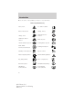
Introduction These are some of the symbols you may see on your vehicle.
Introduction Vehicle Symbol Glossary Power Windows Front/Rear Power Window Lockout Child Safety Door Lock/Unlock Interior Luggage Compartment Release Panic Alarm Engine Oil Engine Coolant Engine Coolant Temperature Do Not Open When Hot Battery Avoid Smoking, Flames, or Sparks Battery Acid Explosive Gas Fan Warning Power Steering Fluid Maintain Correct Fluid Level Service Engine Soon Engine Air Filter Passenger Compartment Air Filter Jack Check Fuel Cap Low Tire Pressure Warning MAX MIN
Instrument Cluster WARNING LIGHTS AND CHIMES Warning lights and gauges can alert you to a vehicle condition that may become serious enough to cause expensive repairs. A warning light may illuminate when a problem exists with one of your vehicle’s functions. Many lights will illuminate when you start your vehicle to make sure the bulb works. If any light remains on after starting the vehicle, refer to the respective system warning light for additional information.
Instrument Cluster WARNING: Under engine misfire conditions, excessive exhaust temperatures could damage the catalytic converter, the fuel system, interior floor coverings or other vehicle components, possibly causing a fire. Check fuel cap: Illuminates when the fuel cap may not be properly installed. Continued driving with this light on may cause the Service engine soon warning light to come on, refer to Fuel filler cap in the Maintenance and Specifications chapter.
Instrument Cluster Airbag readiness: If this light fails to illuminate when the ignition is turned to on, continues to flash or remains on, have the system serviced immediately by your authorized dealer. A chime will sound when there is a malfunction in the indicator light. Safety belt: Reminds you to fasten your safety belt. A Belt-Minder威 chime will also sound to remind you to fasten your safety belt. Refer to the Seating and Safety Restraints chapter to activate/deactivate the Belt-Minder威 chime feature.
Instrument Cluster Overdrive off (if equipped): O/D Illuminates when the overdrive OFF function of the transmission has been turned off, refer to the Driving chapter. If the light flashes steadily or does not illuminate, have the transmission serviced soon, or damage may occur. Speed control (if equipped): Illuminates when the speed control is activated. Turns off when the speed control system is deactivated.
Instrument Cluster Low fuel: Illuminates when the fuel level in the fuel tank is at or near empty (refer to Fuel gauge in this chapter). Door ajar: Illuminates when the ignition is on and any door, the trunk or hood is open. Turn signal: Illuminates when the left or right turn signal or the hazard lights are turned on. If the indicators stay on or flash faster, check for a burned out bulb. High beams: Illuminates when the high beam headlamps are turned on.
Instrument Cluster GAUGES Speedometer: Indicates the current vehicle speed. Engine coolant temperature gauge: Indicates engine coolant temperature. At normal operating temperature, the needle will be in the normal range. If it enters the red section, the engine is overheating. Stop the vehicle as soon as safely possible, switch off the engine and let the engine cool.
Instrument Cluster Odometer: Registers the total miles (kilometers) of the vehicle. If equipped with a message center, refer to Message center in this chapter on how to switch the display between Metric and English. Trip odometer: Registers the distance of individual journeys. • Standard instrument cluster: Press the SELECT/RESET button once to switch from the odometer to the TRIP A or B feature. To reset the trip, press and hold the SELECT/RESET button.
Instrument Cluster MESSAGE CENTER Your vehicle’s message center is capable of monitoring many vehicle systems and will alert you to potential vehicle problems and various conditions with an informational message followed by a long indicator chime. The message center display is located in the instrument cluster. Info Press the INFO button repeatedly to cycle through the following features: TRIP A/B Registers the distance of individual journeys.
Instrument Cluster AVG MPG (L/100km) Average fuel economy displays your average fuel economy in miles/gallon or liters/100 km.
Instrument Cluster 1. CHARGING SYSTEM 2. DOORS 3. TRUNK 4. BRAKE SYSTEM 5. DTE/FUEL LEVEL 6. MYKEY DISTANCE (if programmed) 7. MYKEY(S) PROGRAMMED 8. ADMIN KEYS PROGRAMMED Note: Some systems show a message only if a condition is present. UNITS Displays the current units in English or Metric. Press RESET to change between English and Metric. AUTOLOCK This feature automatically locks all vehicle doors when the vehicle is shifted into any gear, putting the vehicle in motion.
Instrument Cluster System warnings System warnings alert you to possible problems or malfunctions in your vehicle’s operating systems. In the event of a multiple warning situation, the message center will cycle the display to show all warnings by displaying each one for four seconds. The message center will display the last selected feature if there are no more warning messages.
Instrument Cluster CHECK BRAKE SYSTEM — Displayed when the braking system is not operating properly. If the warning stays on or continues to come on, contact your authorized dealer as soon as possible. BRAKE FLUID LEVEL LOW — Indicates the brake fluid level is low and the brake system should be inspected immediately. Refer to Brake/clutch fluid in the Maintenance and Specifications chapter. LOW TIRE PRESSURE — Displayed when one or more tires on your vehicle have low tire pressure.
Instrument Cluster VEHICLE NEAR TOP SPEED — Displayed when a MyKey™ is in use and the MyKey speed limit is on and the vehicle speed is approaching 80 mph (130 km/h). Refer to MyKey™ in the Locks and Security chapter for more information. TOP SPEED MYKEY SETTING — Displayed when a MyKey™ is in use and the MyKey speed limit is on and the vehicle speed is 80 mph (130 km/h). Refer to MyKey™ in the Locks and Security chapter for more information.
Entertainment Systems AUDIO SYSTEMS AM/FM/single CD satellite compatible sound system WARNING: Driving while distracted can result in loss of vehicle control, accident and injury. Ford strongly recommends that drivers use extreme caution when using any device or feature that may take their focus off the road. Your primary responsibility is the safe operation of the vehicle. We recommend against the use of any handheld device while driving and that you comply with all applicable laws.
Entertainment Systems AM/FM Radio / VOL (Power/Volume): Press to turn the radio on/off. Turn the knob to increase/decrease volume. If the volume is set above a certain level and the ignition is turned off, the volume will come back on at a nominal listening level when the ignition switch is turned back on. AM/FM: Press repeatedly to select AM/FM1/FM2 frequency band. TUNE: Turn the knob to go up/down the frequency band in individual increments.
Entertainment Systems another control within those five seconds, the search will not initiate. The 10 strongest stations will be filled and the station stored in preset 1 will begin playing. If there are fewer than 10 strong stations, the system will store the last one in the remaining presets. RBDS Radio Available only in FM mode. This feature allows you to search RBDS-equipped stations for a certain category of music format: CLASSIC, COUNTRY, JAZZ/RB, ROCK, etc.
Entertainment Systems SEEK/TRACK: Press SEEK/TRACK to access the previous/next track. CAT (Category) / FOLD (Folder): In MP3 mode only– Press CAT/FOLD and then press SEEK/TRACK to access the previous/next folder. SCAN: Press for a brief sampling of all tracks on the current disc or MP3 folder. DIRECT: In CD mode– Press DIRECT. The display will read DIRECT TRACK MODE SELECT TRACK. Enter the desired track number using the memory preset buttons (0–9). The system will then begin playing that track.
Entertainment Systems Satellite Radio (if equipped) Satellite radio is available only with a valid SIRIUS radio subscription. Check with your authorized dealer for availability. SIRIUS: Press repeatedly to access satellite radio mode, if equipped. Press repeatedly to cycle through SAT1, SAT2 and SAT3 modes. TUNE/OK: Turn the knob to go to the next / previous available SIRIUS satellite station. DIRECT: Press DIRECT then enter the desired channel (i.e. 002) using the memory preset buttons (0–9).
Entertainment Systems In TEXT MODE: Sometimes the display requires additional text to be displayed. When the < / > indicator is active, press TEXT and then press SEEK/TRACK to view the additional display text. CAT (Category) / FOLD (Folder): Press to switch between turning the most recently selected satellite radio category on or off. The category icon (CAT) will illuminate in the display when a specific category is selected (the icon will not illuminate during CATEGORY ALL).
Entertainment Systems The song will appear in the display for confirmation. Press OK again and the display will read SONG DELETED. If you do not want to / to select either delete the currently listed song, press RETURN or CANCEL. Note: If there are no songs presently saved, the display will read NO SONGS. c. DELETE ALL SONGS: Press OK to delete all song’s from the system’s memory. The display will read ARE YOU SURE ? Press OK to confirm deletion of all saved songs and the display will read ALL DELETED.
Entertainment Systems PIN number to its initial password setting (1234). PIN RESET TO DEFAULT PIN will be displayed. e. RETURN: Press OK when RETURN is displayed and the system will exit back to the satellite radio menu. Sound Adjustments Press SOUND repeatedly to cycle through the following features: BASS: Press TREBLE: Press SEEK/TRACK to adjust the level of bass. SEEK/TRACK SEEK/TRACK BALANCE: Press the left (L) and right (R) speakers. to adjust the level of treble.
Entertainment Systems OK: Your vehicle may be equipped with special phone and media features which will require you to confirm commands by pressing OK. Refer to the SYNC威 information included with your vehicle for further information. (Phone): If your vehicle is equipped with SYNC威, press to access SYNC PHONE features. Refer to the SYNC威 information included with your vehicle for further information. If your vehicle is not equipped with SYNC威, the display will read NO PHONE.
Entertainment Systems To play your portable music player using the auxiliary input jack: 1. Begin with the vehicle parked and the radio turned off. 2. Ensure that the battery in your portable music player is new or fully charged and that the device is turned off. 3. Attach one end of the audio extension cable to the headphone output of your player and the other end of the audio extension cable to the AIJ in your vehicle. 4. Turn the radio on, using either a tuned FM station or a CD loaded into the system.
Entertainment Systems location, such as the center console or the glove box, when the vehicle is in motion. The audio extension cable must be long enough to allow the portable music player to be safely stored while the vehicle is in motion. USB port (if equipped) WARNING: Driving while distracted can result in loss of vehicle control, accident and injury. Ford strongly recommends that drivers use extreme caution when using any device or feature that may take their focus off the road.
Entertainment Systems CD/CD player care Do: • Handle discs by their edges only. (Never touch the playing surface). • Inspect discs before playing. • Clean only with an approved CD cleaner. • Wipe discs from the center out. Don’t: • Expose discs to direct sunlight or heat sources for extended periods of time. • Clean using a circular motion. CD units are designed to play commercially pressed 4.75 in (12 cm) audio compact discs only.
Entertainment Systems CDs with homemade paper (adhesive) labels should not be inserted into the CD player as the label may peel and cause the CD to become jammed. It is recommended that homemade CDs be identified with permanent felt tip marker rather than adhesive labels. Ballpoint pens may damage CDs. Please contact your authorized dealer for further information. Audio system warranty and service Refer to the Warranty Guide for audio system warranty information.
Entertainment Systems Sample MP3 structure If you are burning your own MP3 discs, it is important to understand how the system will read the structures you create. While various files may be present, (files with extensions other than mp3), only files with the .mp3 extension will be played. Other files will be ignored by the system. This enables you to use the same MP3 disc for a variety of tasks on your work computer, home computer and your in-vehicle system. 1 .mp3 1 .mp3 2 2 3 .mp3 3 .mp3 4 .
Entertainment Systems Satellite radio reception factors: To receive the satellite signal, your vehicle has been equipped with a satellite radio antenna located on the roof of your vehicle. The vehicle roof provides the best location for an unobstructed, open view of the sky, a requirement of a satellite radio system.
Entertainment Systems Satellite radio electronic serial number (ESN): This 12–digit Satellite Serial Number is needed to activate, modify or track your satellite radio account. You will need this number when communicating with SIRIUS威. While in satellite radio mode, you can view this number on the radio display by pressing the AUX and preset 1 controls simultaneously. Radio Display ACQUIRING SAT FAULT Condition Radio requires more than two seconds to produce audio for the selected channel.
Entertainment Systems Radio Display NO TEXT Condition Song title information not available. NO TEXT Category information not available. NO SIGNAL Loss of signal from the SIRIUS威 satellite or SIRIUS威 tower to the vehicle antenna. UPDATING Update of channel programming in progress. Satellite service has been deactivated by SIRIUS威 satellite radio. CALL SIRIUS威 1–888–539–7474 Action Required Song title information not available at this time on this channel. The system is working properly.
Climate Controls MANUAL HEATING AND AIR CONDITIONING SYSTEM Fan speed adjustment: Controls the volume of air circulated in 1. the vehicle. 2. R Rear defroster: Press to activate/deactivate the rear window defroster. Refer to Rear window defroster later in this chapter for more information. Defrost: Distributes outside air through the windshield defroster 3. vents and demister vents. Can be used to clear the windshield of fog and thin ice.
Climate Controls 7. : Distributes air through the instrument panel vents, floor vents, rear seat floor vents and demister vents. : Distributes air through the floor vents, rear seat floor vents and 8. demister vents. 9. Temperature control: Controls the temperature of the airflow in the vehicle. Passenger heated seat control (if equipped): Press to 10. activate/deactivate the passenger heated seat. See Heated seats in the Seating and Safety Restraints chapter.
Climate Controls Operating tips • To reduce fog build-up on the windshield during humid weather, (defrost) or (floor/defrost). select • To reduce humidity build-up inside the vehicle, do not drive with the (recirculated air) engaged and A/C off. system off or with • Do not put objects under the front seats that will interfere with the airflow to the back seats. • Remove any snow, ice or leaves from the air intake area at the base of the windshield.
Climate Controls REAR WINDOW DEFROSTER R The rear defroster control is located on the climate control panel and works to clear the rear window of fog and thin ice. The engine must be running to operate the rear window defroster. to turn the rear window defroster on. An indicator light on the Press R control will illuminate when active.
Lights HEADLAMP CONTROL Turns the lamps off. Turns on the parking lamps, instrument panel lamps, license plate lamps and tail lamps. Turns the low beam headlamps on. Fog lamp control (if equipped) The fog lamps can be turned on when the headlamp control is in or position and the the high beams are not turned on. With the key in the on position, pull the headlamp control towards you to turn fog lamps on. The fog lamp on the headlamp indicator light control will illuminate.
Lights Flash-to-pass Pull toward you slightly to activate and release to deactivate. Daytime running lamps (DRL) (if equipped) Turns the headlamps on with a reduced output. To activate: • the ignition must be in the on position and • the headlamp control is in the off or parking lamp position. WARNING: Always remember to turn on your headlamps at dusk or during inclement weather.
Lights AIMING THE HEADLAMPS The headlamps on your vehicle are properly aimed at the assembly plant. If your vehicle has been in an accident, the alignment of your headlamps should be checked by your authorized dealer. Vertical aim adjustment 1. Park the vehicle directly in front of a wall or screen on a level surface, approximately 25 feet (7.6 meters) away. • (1) 8 feet (2.4 meters) • (2) Center height of lamp to ground • (3) 25 feet (7.6 meters) • (4) Horizontal reference line 2.
Lights 5. Locate the vertical adjuster on each headlamp, then use a Phillips #2 screwdriver or 10 mm wrench/socket to adjust the headlamp up or down. 6. Close the hood and turn off the lamps. HORIZONTAL AIM IS NOT REQUIRED FOR THIS VEHICLE AND IS NON-ADJUSTABLE. TURN SIGNAL CONTROL • Push down to activate the left turn signal. • Push up to activate the right turn signal. INTERIOR LAMPS Map lamps To turn on the map lamps, press the outer edge of the clear lens.
Lights Rear dome lamp When the lamp control is in the middle position, the rear dome lamp will come on when a door is opened or the unlock button is pressed on the remote keyless entry. If the control is moved to the driver side position, the lamp will not come on at all. If the control is moved to the passenger side position, the lamp will stay on. Ambient lighting (if equipped) Illuminates four footwells and three cupholders with a choice of several colors.
Lights Examples of acceptable condensation are: • Presence of thin mist (no streaks, drip marks or droplets) • Fine mist covers less than 50% of the lens Examples of unacceptable moisture (usually caused by a lamp water leak) are: • Water puddle inside the lamp • Large water droplets, drip marks or streaks present on the interior of the lens Take your vehicle to a dealer for service if any of the above conditions of unacceptable moisture are present.
Lights Replacing headlamp bulbs 1. Make sure the headlamp control is in the off position and open the hood. 2. Remove four push pins from the radiator grille and pull the grille forward to access the lower screw. 3. Remove three bolts and washers from the headlamp assembly. 4. Carefully pull the headlamp assembly up and away from the vehicle to disengage the hidden spring clip located on the bottom of the headlamp assembly. This may require substantial upward force. 5.
Lights Replacing front parking lamp/turn signal bulbs 1. Make sure the headlamp control is in the off position and open the hood. 2. Remove four push pins from the radiator grille and pull the grille forward to access the lower screw. 3. Remove three bolts and washers from the headlamp assembly. 4. Carefully pull the headlamp assembly up and away from the vehicle to disengage the hidden spring clip located on the bottom of the headlamp assembly. This may require substantial upward force. 5.
Lights 5. Remove the bulb socket from the lamp assembly by turning counterclockwise. 6. Pull the bulb straight out of the socket. Install the new bulb in reverse order. Be sure that the spring clip is not damaged or detached from the housing during the replacement procedure. Replacing tail/brake/backup lights and turn signal bulbs 1. Make sure the headlamp control is in the off position and then open the trunk. 2. Remove two plastic screws and cover from inside the luggage compartment. 3.
Lights Replacing license plate lamp bulbs 1. Make sure the headlamp switch is in the off position. 2. Remove the two screws and the lens from the license plate lamp assembly. 3. Carefully pull the bulb straight out from the lamp assembly. Install new bulb(s) in reverse order. Replacing high-mount brake lamp assembly Your vehicle is equipped with an LED center high-mount stop lamp. It is designed to last the life of the vehicle.
Driver Controls MULTI-FUNCTION LEVER Windshield wiper: Rotate the end of the control away from you to increase the speed of the wipers; rotate towards you to decrease the speed of the wipers. Windshield washer: Press the end of the stalk: • briefly: causes a single swipe of the wipers without washer fluid. • a quick press and hold: the wipers will swipe three times with washer fluid. • a long press and hold: the wipers and washer fluid will be activated for up to ten seconds.
Driver Controls TILT STEERING WHEEL To adjust the steering wheel: 1. Pull the lever down to unlock the steering column. 2. While the lever is in the down position, move the steering wheel up or down until you find the desired position. 3. While holding the steering wheel in place, pull the lever up to its original position to lock the steering column. WARNING: Never adjust the steering wheel when the vehicle is moving.
Driver Controls Compass zone adjustment 1. Determine which magnetic zone you are in for your geographic location by referring to the zone map. 2. Turn ignition to the on position. 3 2 1 15 4 14 13 5 12 6 7 8 9 1011 3. Press and hold the 7 and 9 radio preset buttons together for approximately five seconds until ZONE XX appears in the CID. 4. Press and release the 7 and 9 radio preset buttons together, repeatedly until ZONE XX changes to the correct zone (1–15) in the CID. 5.
Driver Controls 2. To calibrate, press and hold the 7 and 9 radio preset buttons together for approximately 10 seconds until CAL appears. Release the buttons. 3. Slowly drive the vehicle in a circle (less than 3 mph [5 km/h]) until the CAL display changes to the direction value (N, S, E, W, etc.). It may take up to five circles to complete calibration. 4. The compass is now calibrated. CENTER CONSOLE Your vehicle has a variety of console features.
Driver Controls To have full capacity usage of your power point, the engine is required to be running to avoid unintentional discharge of the battery. To prevent the battery from being discharged: • do not use the power point longer than necessary when the engine is not running, • do not leave battery chargers, video game adapters, computers and other devices plugged in overnight or when the vehicle is parked for extended periods. Always keep the power point caps closed when not being used.
Driver Controls Window lock (if equipped) The window lock feature allows only the driver to operate the power windows. To lock out all the window controls (except for the driver’s) press the right side of the control. Press the left side to restore the window controls. INTERIOR MIRROR The interior rear view mirror has two pivot points on the support arm which lets you adjust the mirror up or down and from side to side. WARNING: Do not adjust the mirror while the vehicle is in motion.
Driver Controls EXTERIOR MIRRORS Power side view mirrors (if equipped) WARNING: Do not adjust the mirror while the vehicle is in motion. To adjust your mirrors: 1. Rotate the control clockwise to adjust the right mirror and rotate the control counterclockwise to adjust the left mirror. 2. Move the control in the direction you wish to tilt the mirror. 3. Return to the center position to lock mirrors in place.
Driver Controls Using speed control The speed controls are located on the steering wheel. The following buttons work with speed control: RESUME: Press to resume a set RESUME speed. SET + SET +: Press to set a speed or increase a set speed. SET SET –: Press to decrease a set OFF ON speed. OFF: Press to turn speed control off. ON: Press to turn speed control on. Setting speed control To set speed control: 1. Press and release ON. 2. Accelerate to the desired speed. 3. Press and release SET +. 4.
Driver Controls Increasing speed while using speed control To set a higher speed: • Press and hold SET + until you get to the desired speed, then release. You can also use SET + to operate the tap-up function. Press and release SET + to increase the vehicle set speed in 1 mph (1.6 km/h) increments. • Use the accelerator pedal to get to the desired speed, then press and release SET +.
Driver Controls SYNC威 hands free control feature (if equipped) briefly to use the voice Press command feature. You will hear a tone and LISTENING will appear in the radio display. Press and to exit voice command. hold to activate phone mode or Press answer a phone call. Press and to end call or exit phone hold mode. to scroll through various menus and selections. Press Press OK to confirm your selection. For further information on the SYNC威 system, refer to the SYNC威 supplement.
Driver Controls To open the moon roof: Press and release the SLIDE control. The moon roof will open to the “comfort” position. Press and release the control again to fully open. Press the switch again to stop the moon roof. WARNING: When closing the moon roof, you should verify that it is free of obstructions and ensure that children and/or pets are not in the proximity of the moon roof opening. To close the moon roof: Pull and release the SLIDE control, the moon roof will close automatically.
Driver Controls • Release the switch and immediately press and hold it again. The moon roof will close, open fully and then close again. Do not release the switch before the moon roof has reached the closed position for the second time. Safety mode: If the system detects a malfunction, it enters a safety mode. The moon roof will move about 0.5 seconds at a time and then stop again. Press the switch repeatedly until the moon roof is closed. Have the system checked by your authorized dealer immediately.
Locks and Security KEYS One key operates all the locks and starts the vehicle. Always carry a spare key with you in case of an emergency. Your keys are programmed to your vehicle; using a non-programmed key will not permit your vehicle to start. If you lose your authorized dealer supplied keys, replacement keys are available through your authorized dealer. Refer to the SecuriLock威 passive anti-theft system section later in this chapter for more information.
Locks and Security • The AdvanceTrac威 system cannot be turned off. When this optional setting is on, the MyKey™ user will not be able to deactivate the system. Note: It may be beneficial to deactivate the AdvanceTrac威 system if the vehicle is stuck in snow, mud or sand. Create a MyKey™ To program MyKey™ on one of the keys programmed to the vehicle, insert the key that you want to make a MyKey™ into the ignition.
Locks and Security 4. On any of the menus press RESET to highlight your choice with the <…>. 5. Press SETUP to enter your choice. The next optional setting will be displayed. 6. Repeat Steps 4 and 5 until you are done changing the optional settings. Clear MyKey™ To reset all MyKeys™ as admin keys, do the following: 1. Turn the vehicle on using the admin key. 2. Press SETUP until PRESS RESET TO CLEAR MYKEY is displayed. 3. Press and release the RESET button. HOLD RESET TO CONFIRM CLEAR is displayed. 4.
Locks and Security Vehicles equipped with traditional keys: When using a Ford-approved remote start system, the default settings will recognize the remote start system as an additional admin key with its associated privileges. Owners of vehicles equipped with traditional keys should program the remote start system as a MyKey™ in addition to the key that they have already programmed as a MyKey™. To program the remote start system as MyKey™, do the following: 1. Enter the vehicle and close all doors. 2.
Locks and Security Troubleshooting Condition Can’t create a MyKey™ Cannot program the MyKey™ optional settings Cannot clear MyKey™ Lost the only admin key Lost any key I accidentally programmed all keys as MyKeys™ Potential Causes • Key in the ignition is already a MyKey™. • Key in the ignition is the last remaining admin key (there always has to be at least one admin key). • Intelligent access key (if equipped) not in the backup slot — for vehicles with push button start.
Locks and Security Condition No MyKey™ function with intelligent access key (push button start) (if equipped) MyKey™ programmed total includes one additional key Admin keys programmed total includes one additional key MyKey™ miles do not accumulate Potential Causes • An admin key is present at vehicle start • No MyKeys™ are programmed to the vehicle. Refer to Create a MyKey™ section • Unknown key has been programmed to the vehicle as a MyKey™. • Vehicle is equipped with a remote start system.
Locks and Security The vehicle can still be locked, with the key in the ignition, by locking the driver’s door with a key or using the lock control on the remote entry key fob. If both front doors are closed, the vehicle can be locked from any method, regardless of whether the key is in the ignition or not.
Locks and Security Power door unlock/lock procedure Before starting, ensure the ignition is in the off position and all vehicle doors are closed. You must complete Steps 1–5 within 30 seconds or the procedure will have to be repeated. If the procedure needs to be repeated, wait a minimum of 30 seconds before beginning again. 1. Place the key in the ignition and turn the ignition to the on position. control 2. Press the power door on the door panel three times. 3.
Locks and Security Deactivating/activating autounlock feature Your vehicle comes with the autounlock features activated; there are three methods to enable/disable this feature: • Through your authorized dealer, • by using a power door unlock/lock sequence • or by using the instrument cluster message center. Refer to Message center in the Instrument Cluster chapter. Note: The autounlock feature can be activated/deactivated independently of the autolock feature.
Locks and Security CHILDPROOF DOOR LOCKS • When these locks are set, the rear doors cannot be opened from the inside. • The rear doors can be opened from the outside when the childproof door locks are set, but the doors are unlocked. The childproof locks are located on the rear edge of each rear door and must be set separately for each door. Setting the lock for one door will not automatically set the lock for both doors.
Locks and Security To open the luggage compartment door (lid) from within the luggage compartment, pull the illuminated “T” shaped handle and push up on the trunk lid. The handle is composed of a material that will glow for hours in darkness following brief exposure to ambient light. The “T” shaped handle will be located either on the luggage compartment door (lid) or inside the luggage compartment near the tail lamps.
Locks and Security REMOTE ENTRY SYSTEM This device complies with part 15 of the FCC rules and with RSS-210 of Industry Canada. Operation is subject to the following two conditions: (1) This device may not cause harmful interference, and (2) This device must accept any interference received, including interference that may cause undesired operation. Changes or modifications not expressly approved by the party responsible for compliance could void the user’s authority to operate the equipment.
Locks and Security The remote entry system activates the illuminated entry feature. This feature turns on the lamps for 25 seconds or until the ignition is turned to the on position. The dome lamp control must be set to the ON position in order for the illuminated entry feature to operate. Programming unlocking mode (if equipped) The unlocking mode on the remote entry transmitter can be programmed.
Locks and Security • Ensure that the trunk is closed and latched before driving your vehicle. Failure to properly latch the trunk may cause objects to fall out or block the driver’s rear view. Replacing the battery The remote entry transmitter uses one coin type three-volt lithium battery CR2032 or equivalent. To replace the battery: 1. Twist a thin coin between the two halves of the remote entry transmitter near the key ring.
Locks and Security How to reprogram your remote entry transmitters You must have all remote entry transmitters (maximum of four) available before beginning this procedure. If all remote entry transmitters are not present during the programming procedure, the transmitters that are not present during programming will no longer operate the vehicle. Note: Ensure the brake pedal is not pressed during this sequence. To reprogram the remote entry transmitters: 1. Ensure the vehicle is electronically unlocked. 2.
Locks and Security The lights will not turn off if: • they have been turned on with the dimmer control, or • any door is open. Illuminated exit • When all vehicle doors and the trunk are closed, and the key is removed from the ignition, the interior lamps and parking lamps will illuminate. The lamps will turn off if all the doors and the trunk remain closed and • 25 seconds elapse, or • the key is inserted in the ignition.
Locks and Security Note: Large metallic objects, electronic devices that are used to purchase gasoline or similar items, or a second coded key on the same key chain may cause vehicle starting issues. You need to prevent these objects from touching the coded key while starting the engine. These objects will not cause damage to the coded key, but may cause a momentary issue if they are too close to the key when starting the engine.
Locks and Security Programming spare keys You can program your own coded keys to your vehicle. Please read and understand the entire procedure before you begin. Tips: • A maximum of eight keys can be coded to your vehicle. • Only use SecuriLock威 keys. • You must have two previously programmed coded keys (keys that already operate your vehicle’s engine) and the new unprogrammed key(s) readily accessible.
Locks and Security 10. Turn the ignition from the 1 (off) position to the 3 (on) position. Keep the ignition in the 3 (on) position for at least one second, but no more than 10 seconds. 11. Your new, unprogrammed key is now programmed. If the key has been successfully programmed it will start the vehicle’s engine and the theft indicator light will illuminate for three seconds and then go out.
Locks and Security Disarming the system You can disarm the system by any of the following actions: control on your remote entry • Unlock the doors by pressing the transmitter. • Turn the ignition to the on or start position with a programmed coded ignition key. • Press the panic control on the remote entry transmitter. This will only shut off the horn and turn lamps when the alarm is sounding. The alarm system will still be armed.
Seating and Safety Restraints FRONT SEATING WARNING: Reclining the seatback can cause an occupant to slide under the seat’s safety belt, resulting in severe personal injuries in the event of a collision. WARNING: Do not pile cargo higher than the seatbacks to reduce the risk of injury in a collision or sudden stop. WARNING: Before returning the seatback to its original position, make sure that cargo or any objects are not trapped behind the seatback.
Seating and Safety Restraints To adjust the head restraint, do the following: 1. Adjust the seatback to an upright driving/riding position. 2. Raise the head restraint by pulling up on the head restraint. 3. Lower the head restraint by pressing and holding the guide sleeve adjust release button and pushing down on the head restraint. Properly adjust the head restraint so that the top of the head restraint is even with the top of your head and positioned as close as possible to the back of your head.
Seating and Safety Restraints To remove the adjustable head restraint, do the following: 1. Pull up the head restraint until it reaches the highest adjustment position. 2. Simultaneously press and hold both the adjust/release button and the unlock/remove button, then pull up on the head restraint. To reinstall the adjustable head restraint, do the following: 1. Insert the two stems into the guide sleeve collars. 2. Push the head restraint down until it locks.
Seating and Safety Restraints WARNING: To minimize the risk of neck injury in the event of a crash, head restraints must be installed properly. Adjusting the front manual seat WARNING: Sitting improperly out of position or with the seat back reclined too far can take off weight from the seat cushion and affect the decision of the passenger sensing system, resulting in serious injury or death in a crash. Always sit upright against your seatback, with your feet on the floor.
Seating and Safety Restraints Pull up on the control to raise the seat and push down on the control to lower the seat. Lift the control to adjust the angle of the seatback. WARNING: Reclining the seatback can cause an occupant to slide under the seat’s safety belt, resulting in severe personal injuries in the event of a collision.
Seating and Safety Restraints Heated seats (if equipped) WARNING: Persons who are unable to feel pain to the skin because of advanced age, chronic illness, diabetes, spinal cord injury, medication, alcohol use, exhaustion, or other physical conditions, must exercise care when using the seat heater. The seat heater may cause burns even at low temperatures, especially if used for long periods of time.
Seating and Safety Restraints Tip/slide front passenger seat (if equipped) Lift the control and fold the seatback forward. The seat can be slid forward to allow easier entry to the rear seats. Slide the seat back and fold back the seatback until it locks with a distinct click. Rock the seat to ensure that the catch is securely engaged. WARNING: Do not place objects behind the seat which could prevent the engagement of the seat lock.
Seating and Safety Restraints Folding down the rear seat One or both rear seatbacks can be folded down to provide additional cargo space. To lower the seatback(s) from inside the vehicle, do the following: 1. Lower the head restraint (if equipped) to the lowest position. 2. Pull the strap located on the inboard side of the seatback (passenger side) or on the outboard side of the seatback (driver side) to release it. 3. Fold the seatback down.
Seating and Safety Restraints • • • • • • • Driver’s seat position sensor. Front crash severity sensor. Front passenger sensing system “Passenger airbag off” or “pass airbag off” indicator lamp Restraints Control Module (RCM) with impact and safing sensors. Restraint system warning light and backup tone. The electrical wiring for the airbags, crash sensor(s), safety belt pretensioners, front safety belt usage sensors, driver seat position sensor, and indicator lights.
Seating and Safety Restraints Driver’s seat position sensor The driver’s seat position sensor allows your Personal Safety System to tailor the deployment level of the driver dual-stage airbag based on seat position. The system is designed to help protect smaller drivers sitting close to the driver airbag by providing a lower airbag output level.
Seating and Safety Restraints Front safety belt usage sensors The front safety belt usage sensors detect whether or not the driver and front outboard passenger safety belts are fastened. This information allows your Personal Safety System to tailor the airbag deployment and safety belt pretensioner activation depending upon safety belt usage.
Seating and Safety Restraints If any of these things happen, even intermittently, have the Personal Safety System™ serviced at an authorized dealer immediately. Unless serviced, the system may not function properly in the event of a collision. Safety belt precautions WARNING: Always drive and ride with your seatback upright and the lap belt snug and low across the hips. WARNING: To reduce the risk of injury, make sure children sit where they can be properly restrained.
Seating and Safety Restraints WARNING: When possible, all children 12 years old and under should be properly restrained in a rear seating position. WARNING: Front and rear seat occupants, including pregnant women, should wear safety belts for optimum protection in an accident. Combination lap and shoulder belts 1. Insert the belt tongue into the proper buckle (the buckle closest to the direction the tongue is coming from) until you hear a snap and feel it latch.
Seating and Safety Restraints Pregnant women should always wear their safety belt. The lap belt portion of a combination lap and shoulder belt should be positioned low across the hips below the belly and worn as tight as comfort will allow. The shoulder belt should be positioned to cross the middle of the shoulder and the center of the chest.
Seating and Safety Restraints When to use the automatic locking mode This mode should be used any time a child safety seat, except a booster, is installed in passenger front or rear seating positions. Children 12 years old and under should be properly restrained in a rear seating position whenever possible. Refer to Safety restraints for children or Safety seats for children later in this chapter. How to use the automatic locking mode • Buckle the combination lap and shoulder belt.
Seating and Safety Restraints WARNING: After any vehicle collision, the safety belt system at all passenger seating positions must be checked by an authorized dealer to verify that the “automatic locking retractor” feature for child seats is still functioning properly. In addition, all safety belts should be checked for proper function.
Seating and Safety Restraints 2. Be sure the belt is not twisted. If the belt is twisted, remove the twist. 3. Insert the belt tongue into the proper buckle for your seating position until you hear a snap and feel it latch. 4. Make sure the tongue is securely fastened to the buckle by pulling on the tongue. WARNING: The lap belt should fit snugly and as low as possible around the hips, not across the waist.
Seating and Safety Restraints WARNING: Position the safety belt height adjusters so that the belt rests across the middle of your shoulder. Failure to adjust the safety belt properly could reduce the effectiveness of the seat belt and increase the risk of injury in a collision. Safety belt pretensioner Your vehicle is equipped with safety belt pretensioners at the driver and front outboard passenger seating positions.
Seating and Safety Restraints Conditions of operation If... The driver’s safety belt is not buckled before the ignition switch is turned to the on position... The driver’s safety belt is buckled while the indicator light is illuminated and the warning chime is sounding... The driver’s safety belt is buckled before the ignition switch is turned to the on position... Then... The safety belt warning light illuminates 1-2 minutes and the warning chime sounds 4-8 seconds.
Seating and Safety Restraints If... The driver’s and front passenger’s safety belts are buckled before the ignition switch is turned to the on position or less than 1-2 minutes have elapsed since the ignition switch has been turned to on... The driver’s or front passenger’s safety belt is not buckled when the vehicle has reached at least 3 mph (5 km/h) and 1-2 minutes have elapsed since the ignition switch has been turned to on...
Seating and Safety Restraints The following are reasons most often given for not wearing safety belts (All statistics based on U.S. data): Reasons given... Consider... “Crashes are rare 36700 crashes occur every day. The more we events” drive, the more we are exposed to “rare” events, even for good drivers. 1 in 4 of us will be seriously injured in a crash during our lifetime. “I’m not going 3 of 4 fatal crashes occur within 25 miles (40 km) far” of home.
Seating and Safety Restraints WARNING: Do not sit on top of a buckled safety belt or insert a latchplate into the buckle to avoid the Belt-Minder威 chime. To do so may adversely affect the performance of the vehicle’s airbag system. Deactivating/activating the Belt-Minder姞 feature The driver and front passenger Belt-Minder威 are deactivated/activated independently. When deactivating/activating one seating position, do not buckle the other position as this will terminate the process.
Seating and Safety Restraints • Step 3 must be completed within 50 seconds after the safety belt warning light turns off. 3. For the seating position being disabled, buckle then unbuckle the safety belt nine times at a moderate speed, ending in the unbuckled state. • After Step 3, the safety belt warning light will be turned on for three seconds. 4. Within approximately seven seconds of the light turning off, buckle then unbuckle the safety belt.
Seating and Safety Restraints Important SRS precautions The SRS is designed to work with the safety belt to help protect the driver and right front passenger from certain upper body injuries. Airbags DO NOT inflate slowly; there is a risk of injury from a deploying airbag. WARNING: All occupants of the vehicle, including the driver, should always properly wear their safety belts, even when an air bag supplemental restraint system (SRS) is provided.
Seating and Safety Restraints WARNING: Do not attempt to service, repair, or modify the airbag supplemental restraint systems or its fuses. Contact your authorized dealer as soon as possible. Children and airbags Children must always be properly restrained. Accident statistics suggest that children are safer when properly restrained in the rear seating positions than in the front seating position. Failure to follow these instructions may increase the risk of injury in a collision.
Seating and Safety Restraints The airbags inflate and deflate rapidly upon activation. After airbag deployment, it is normal to notice a smoke-like, powdery residue or smell the burnt propellant. This may consist of cornstarch, talcum powder (to lubricate the bag) or sodium compounds (e.g., baking soda) that result from the combustion process that inflates the airbag. Small amounts of sodium hydroxide may be present which may irritate the skin and eyes, but none of the residue is toxic.
Seating and Safety Restraints • safety belt pretensioners • one or more impact and safing sensors. • Front passenger sensing system. Refer to Front passenger sensing system later in this chapter. • “Passenger airbag off” or “pass airbag off” indicator lamp. Refer to Front passenger sensing system later in this chapter. • a readiness light and tone. • diagnostic module. • and the electrical wiring which connects the components.
Seating and Safety Restraints Note: When the passenger airbag off light is illuminated, the passenger (seat mounted) side airbag may be disabled to avoid the risk of airbag deployment injuries. The front passenger sensing system uses a ⬙passenger airbag off⬙ or ⬙pass airbag off⬙ indicator which will illuminate and stay lit to remind you that the front passenger frontal airbag is disabled. The indicator lamp is located on the center stack area of the instrument panel.
Seating and Safety Restraints • Restart the vehicle and have the person remain in this position for about two minutes. This will allow the system to detect that person and enable the passenger’s frontal airbag. • If the indicator lamp remains lit even after this, the person should be advised to ride in the rear seat.
Seating and Safety Restraints Objects Pass Airbag Off Indicator Lamp Unlit Passenger Airbag Small (i.e. three-ring Disabled binder, small purse, bottled water) Medium (i.e.
Seating and Safety Restraints In case there is a problem with the front passenger sensing system, the airbag readiness lamp in the instrument cluster will stay lit. If the airbag readiness lamp is lit, do the following: The driver and/or adult passengers should check for any objects that may be lodged underneath the front passenger seat or cargo interfering with the seat.
Seating and Safety Restraints A difficulty with the system is indicated by one or more of the following: • The readiness light (same light for front and side airbag system) will either flash or stay lit. • The readiness light will not illuminate immediately after ignition is turned on. • A series of five beeps will be heard. The tone pattern will repeat periodically until the problem and/or light are repaired.
Seating and Safety Restraints How does the side airbag system work? The design and development of the side airbag system included recommended testing procedures that were developed by a group of automotive safety experts known as the Side Airbag Technical Working Group. These recommended testing procedures help reduce the risk of injuries related to the deployment of side airbags.
Seating and Safety Restraints WARNING: Several air bag system components get hot after inflation. Do not touch them after inflation. WARNING: If the side airbag has deployed, the airbag will not function again. The side airbag system (including the seat) must be inspected and serviced by an authorized dealer. If the airbag is not replaced, the unrepaired area will increase the risk of injury in a collision.
Seating and Safety Restraints WARNING: Do not attempt to service, repair, or modify the side air curtain system, its fuses, the A, B, or C pillar trim, or the headliner on a vehicle containing a side air curtain. See your authorized dealer. WARNING: All occupants of the vehicle, including the driver, should always wear their safety belts even when an inflatable curtain is provided. WARNING: To reduce the risk of injury, do not obstruct or place objects in the deployment zone of the inflatable curtain.
Seating and Safety Restraints • Two pressure sensors located in the front doors. • Two crash sensors located on the rocker panel between the “B” and “C” pillars near the floor. Side air curtains and side airbags, in combination with safety belts, can help reduce the risk of severe injuries in the event of a significant side impact collision. Children 12 years old and under should always be properly restrained in the rear seats.
Seating and Safety Restraints WARNING: If the side air curtain has deployed, the air curtain will not function again. The side air curtain system (including the A, B and C pillar trim and headliner) must be inspected and serviced by an authorized dealer. If the air curtain is not replaced, the unrepaired area will increase the risk of injury in a collision. Determining if the system is operational The SRS uses a readiness light in the instrument cluster or a tone to indicate the condition of the system.
Seating and Safety Restraints The feature will continue to operate until the vehicle runs out of power. Disposal of airbags and airbag equipped vehicles (including pretensioners) Contact your authorized dealer as soon as possible. Airbags MUST BE disposed of by qualified personnel. SAFETY RESTRAINTS FOR CHILDREN See the following sections for directions on how to properly use safety restraints for children.
Seating and Safety Restraints Recommendations for Safety Restraints for Children Recommended Child size, height, weight, or age restraint type Infants or Children weighing 40 lb (18 kg) or Use a child safety toddlers less (generally age four or younger) seat (sometimes called an infant carrier, convertible seat, or toddler seat). Use a belt-positioning Small Children who have outgrown or no booster seat.
Seating and Safety Restraints Recommendations for attaching child safety restraints for children Restraint Type Rear facing child seat Forward facing child seat Forward facing child seat Use any attachment method as indicated below by “X” LATCH LATCH Safety Safety Safety (lower (lower belt belt and belt Child anchors anchors and LATCH only Weight and only) top (lower top tether anchors tether anchor and top anchor) tether anchor) Up to 48 lb X X (21 kg) Up to 48 lb X X X (21 kg) Over 48 lb X X (21 kg) W
Seating and Safety Restraints WARNING: Never let a passenger hold a child on his or her lap while the vehicle is moving. The passenger cannot protect the child from injury in a collision, which may result in serious injury or death. WARNING: Never use pillows, books, or towels to boost a child. They can slide around and increase the likelihood of injury or death in a collision. WARNING: Always restrain an unoccupied child seat or booster seat.
Seating and Safety Restraints Follow all the safety restraint and airbag precautions that apply to adult passengers in your vehicle. If the child is the proper height, age, and weight (as specified by your child safety seat or booster manufacturer), fits the restraint and can be restrained properly, then restrain the child in the child safety seat or with the belt-positioning booster.
Seating and Safety Restraints position whenever possible. If all children cannot be seated and restrained properly in a rear seating position, properly restrain the largest child in the front seat. When installing a child safety seat with combination lap/shoulder belts: • Use the correct safety belt buckle for that seating position. • Insert the belt tongue into the proper buckle until you hear a snap and feel it latch. Make sure the tongue is securely fastened in the buckle.
Seating and Safety Restraints 2. Pull down on the shoulder belt and then grasp the shoulder belt and lap belt together. 3. While holding the shoulder and lap belt portions together, route the tongue through the child seat according to the child seat manufacturer’s instructions. Be sure the belt webbing is not twisted. 4. Insert the belt tongue into the proper buckle (the buckle closest to the direction the tongue is coming from) for that seating position until you hear a snap and feel the latch engage.
Seating and Safety Restraints 5. To put the retractor in the automatic locking mode, grasp the shoulder portion of the belt and pull downward until all of the belt is pulled out. Note: The automatic locking mode is available on the front passenger and rear outboard seats only. The rear center seating position has a cinch tongue. Refer to Installing child safety seats in cinch tongue combination lap and shoulder belt seating positions (rear center position only) in this chapter. 6.
Seating and Safety Restraints 10. Before placing the child in the seat, forcibly move the seat forward and back to make sure the seat is securely held in place. To check this, grab the seat at the belt path and attempt to move it side to side and forward and back. There should be no more than 1 inch (2.5 cm) of movement for proper installation. 11. Ford recommends checking with a NHTSA Certified Child Passenger Safety Technician (CPST) to make certain the child restraint is properly installed.
Seating and Safety Restraints 2. Slide the tongue up the webbing. 3. While holding both shoulder and lap portions next to the tongue, route the tongue and webbing through the child seat according to the child seat manufacturer’s instructions. Be sure that the belt webbing is not twisted. 4. Insert the belt tongue into the proper buckle for that seating positions until you hear a snap and feel it latch. Make sure the tongue is securely latched to the buckle by pulling on the tongue.
Seating and Safety Restraints 5. Remove remaining slack from the belt. Force the seat down with extra weight, e.g., by pressing down or kneeling on the child restraint while pulling up on the shoulder belt in order to force slack from the belt. This is necessary to remove the remaining slack that will exist once the additional weight of the child is added to the child restraint. It also helps to achieve the proper snugness of the child seat to the vehicle.
Seating and Safety Restraints equipped seating positions in your vehicle. This type of attachment method eliminates the need to use safety belts to attach the child seat, however the safety belt can still be used to attach the child seat. For forward-facing child seats, the top tether strap must also be attached to the proper top tether anchor, if a top tether strap has been provided with your child seat. Ford Motor Company recommends the use of a child safety seat having a top tether strap.
Seating and Safety Restraints WARNING: Depending on where you secure a child restraint, and depending on the child restraint design, you may block access to certain safety belt buckle assemblies and/or LATCH lower anchors, rendering those features potentially unusable. To avoid risk of injury, occupants should only use seating positions where they are able to be properly restrained.
Seating and Safety Restraints Attaching child safety seats with tether straps Many forward-facing child safety seats include a tether strap which extends from the back of the child safety seat and hooks to an anchoring point called the top tether anchor. Tether straps are available as an accessory for many older safety seats.
Seating and Safety Restraints 2. Locate the correct anchor for the selected seating position. 3. Open the tether anchor cover. 4. Clip the tether strap to the anchor as shown. If the tether strap is clipped incorrectly, the child safety seat may not be retained properly in the event of a collision. 5. Tighten the child safety seat tether strap according to the manufacturer’s instructions. If the safety seat is not anchored properly, the risk of a child being injured in a collision greatly increases.
Seating and Safety Restraints Although the lap/shoulder belt will provide some protection, children who have outgrown a typical child seat are still too small for lap/shoulder belts to fit properly, and wearing an improperly fitted vehicle safety belt could increase the risk of serious injury in a crash. To improve the fit of both the lap and shoulder belt on children who have outgrown child safety seats, Ford Motor Company recommends use of a belt-positioning booster.
Seating and Safety Restraints Types of booster seats There are generally two types of belt-positioning booster seats: backless and high back. Always use booster seats in conjunction with the vehicle lap/shoulder belt. • Backless booster seats If your backless booster seat has a removable shield, remove the shield. If a vehicle seating position has a low seat back or no head restraint, a backless booster seat may place your child’s head (as measured at the tops of the ears) above the top of the seat.
Seating and Safety Restraints Children and booster seats vary in size and shape. Choose a booster that keeps the lap belt low and snug across the hips, never up across the stomach, and lets you adjust the shoulder belt to cross the chest and rest snugly near the center of the shoulder. The drawings below compare the ideal fit (center) to a shoulder belt uncomfortably close to the neck and a shoulder belt that could slip off the shoulder.
Seating and Safety Restraints Follow all instructions provided by the manufacturer of the booster seat. WARNING: Never place, or allow a child to place, the shoulder belt under a child’s arm or behind the back because it reduces the protection for the upper part of the body and may increase the risk of injury or death in a collision. Child restraint and safety belt maintenance Inspect the vehicle safety belts and child safety seat systems periodically to make sure they work properly and are not damaged.
Tires, Wheels and Loading INFORMATION ABOUT UNIFORM TIRE QUALITY GRADING Tire Quality Grades apply to new pneumatic passenger car tires. The Quality grades can be found where applicable on the tire sidewall between tread shoulder and maximum section width. For example: • Treadwear 200 Traction AA Temperature A These Tire Quality Grades are determined by standards that the United States Department of Transportation has set. Tire Quality Grades apply to new pneumatic passenger car tires.
Tires, Wheels and Loading WARNING: The traction grade assigned to this tire is based on straight-ahead braking traction tests, and does not include acceleration, cornering, hydroplaning or peak traction characteristics. Temperature A B C The temperature grades are A (the highest), B and C, representing the tire’s resistance to the generation of heat and its ability to dissipate heat when tested under controlled conditions on a specified indoor laboratory test wheel.
Tires, Wheels and Loading Increasing the inflation pressure beyond this pressure will not increase the tire’s load carrying capability. • kPa: Kilopascal, a metric unit of air pressure. • PSI: Pounds per square inch, a standard unit of air pressure. • Cold inflation pressure: The tire pressure when the vehicle has been stationary and out of direct sunlight for an hour or more and prior to the vehicle being driven for 1 mile (1.6 km).
Tires, Wheels and Loading WARNING: Under-inflation is the most common cause of tire failures and may result in severe tire cracking, tread separation or “blowout”, with unexpected loss of vehicle control and increased risk of injury. Under-inflation increases sidewall flexing and rolling resistance, resulting in heat buildup and internal damage to the tire. It also may result in unnecessary tire stress, irregular wear, loss of vehicle control and accidents.
Tires, Wheels and Loading when you get to the pump. It is normal for tires to heat up and the air pressure inside to go up as you drive. 2. Remove the cap from the valve on one tire, then firmly press the tire gauge onto the valve and measure the pressure. 3. Add enough air to reach the recommended air pressure. Note: If you overfill the tire, release air by pressing on the metal stem in the center of the valve. Then recheck the pressure with your tire gauge. 4. Replace the valve cap. 5.
Tires, Wheels and Loading Improper or inadequate vehicle maintenance can cause tires to wear abnormally. Inspect all your tires, including the spare, frequently, and replace them if one or more of the following conditions exist: Tire wear When the tread is worn down to 1/16th of an inch (2 mm), tires must be replaced to help prevent your vehicle from skidding and hydroplaning.
Tires, Wheels and Loading U.S. DOT Tire Identification Number (TIN) Both U.S. and Canada Federal regulations require tire manufacturers to place standardized information on the sidewall of all tires. This information identifies and describes the fundamental characteristics of the tire and also provides a U.S. DOT Tire Identification Number for safety standard certification and in case of a recall. This begins with the letters “DOT” and indicates that the tire meets all federal standards.
Tires, Wheels and Loading WARNING: When mounting replacement tires and wheels, you should not exceed the maximum pressure indicated on the sidewall of the tire to set the beads without additional precautions listed below. If the beads do not seat at the maximum pressure indicated, re-lubricate and try again.
Tires, Wheels and Loading • Do not run over curbs or hit the tire against a curb when parking WARNING: If your vehicle is stuck in snow, mud, sand, etc., do not rapidly spin the tires; spinning the tires can tear the tire and cause an explosion. A tire can explode in as little as three to five seconds. WARNING: Do not spin the wheels at over 35 mph (56 km/h). The tires may fail and injure a passenger or bystander.
Tires, Wheels and Loading • Front-wheel drive (FWD) vehicles (front tires at top of diagram) Sometimes irregular tire wear can be corrected by rotating the tires. Note: If your tires show uneven wear ask an authorized dealer to check for and correct any wheel misalignment, tire imbalance or mechanical problem involved before tire rotation. Note: Your vehicle may be equipped with a dissimilar spare tire/wheel.
Tires, Wheels and Loading Information on “P” type tires P215/65R15 95H is an example of a tire size, load index and speed rating. The definitions of these items are listed below. (Note that the tire size, load index and speed rating for your vehicle may be different from this example.) 1. P: Indicates a tire, designated by the Tire and Rim Association (T&RA), that may be used for service on cars, SUVs, minivans and light trucks.
Tires, Wheels and Loading Note: You may not find this information on all tires because it is not required by federal law. Letter rating Speed rating - mph (km/h) M 81 mph (130 km/h) N 87 mph (140 km/h) Q 99 mph (159 km/h) R 106 mph (171 km/h) S 112 mph (180 km/h) T 118 mph (190 km/h) U 124 mph (200 km/h) H 130 mph (210 km/h) V 149 mph (240 km/h) W 168 mph (270 km/h) Y 186 mph (299 km/h) Note: For tires with a maximum speed capability over 149 mph (240 km/h), tire manufacturers sometimes use the letters ZR.
Tires, Wheels and Loading 11. Maximum Load: Indicates the maximum load in kilograms and pounds that can be carried by the tire. Refer to the Safety Compliance Certification Label, which is located on the B-Pillar or the edge of the driver’s door, for the correct tire pressure for your vehicle. 12. Treadwear, Traction and Temperature Grades • Treadwear: The treadwear grade is a comparative rating based on the wear rate of the tire when tested under controlled conditions on a specified government test course.
Tires, Wheels and Loading Additional information contained on the tire sidewall for “LT” type tires “LT” type tires have some additional information beyond those of “P” type tires; these differences are described below. Note: Tire Quality Grades do not apply to this type of tire. 1. LT: Indicates a tire, designated by the Tire and Rim Association (T&RA), that is intended for service on light trucks. 2.
Tires, Wheels and Loading Information on “T” type tires “T” type tires have some additional information beyond those of “P” type tires; these differences are described below: T145/80D16 is an example of a tire size. Note: The temporary tire size for your vehicle may be different from this example. Tire Quality Grades do not apply to this type of tire. 1.
Tires, Wheels and Loading TIRE PRESSURE MONITORING SYSTEM (TPMS) Each tire, including the spare (if provided), should be checked monthly when cold and inflated to the inflation pressure recommended by the vehicle manufacturer on the vehicle placard or tire inflation pressure label. (If your vehicle has tires of a different size than the size indicated on the vehicle placard or tire inflation pressure label, you should determine the proper tire inflation pressure for those tires.
Tires, Wheels and Loading following two conditions: (1) This device may not cause harmful interference, and (2) This device must accept any interference received, including interference that may cause undesired operation. WARNING: The tire pressure monitoring system is NOT a substitute for manually checking tire pressure. The tire pressure should be checked periodically (at least monthly) using a tire gauge, see Inflating your tires in this chapter.
Tires, Wheels and Loading To restore the full functionality of the tire pressure monitoring system, have the damaged road wheel/tire repaired and remounted on your vehicle. For additional information, refer to Changing tires with TPMS in this section. When you believe your system is not operating properly The main function of the tire pressure monitoring system is to warn you when your tires need air. It can also warn you in the event the system is no longer capable of functioning as intended.
Tires, Wheels and Loading Low tire pressure warning light Flashing warning light Possible cause Customer action required Spare tire in use Your temporary spare tire is in use. Repair the damaged road wheel and re-mount it on the vehicle to restore system functionality. For a description of how the system functions under these conditions, refer to When your temporary spare tire is installed in this section.
Tires, Wheels and Loading SNOW TIRES AND CHAINS WARNING: Snow tires must be the same size, load index, speed rating as those originally provided by Ford. Use of any tire or wheel not recommended by Ford can affect the safety and performance of your vehicle, which could result in an increased risk of loss of vehicle control, vehicle rollover, personal injury and death.
Tires, Wheels and Loading Payload – is the combined weight of cargo and passengers that the vehicle is carrying. The maximum payload for your vehicle can be found on the Tire Label on the B-Pillar or the edge of the driver’s door (vehicles exported outside the US and Canada may not have a Tire Label). Look for “THE COMBINED WEIGHT OF OCCUPANTS AND CARGO SHOULD NEVER EXCEED XXX kg OR XXX lb.” for maximum payload.
Tires, Wheels and Loading Example only: Cargo Weight – includes all weight added to the Base Curb Weight, including cargo and optional equipment. GAW (Gross Axle Weight) – is the total weight placed on each axle (front and rear) – including vehicle curb weight and all payload.
Tires, Wheels and Loading GAWR (Gross Axle Weight Rating) – is the maximum allowable weight that can be carried by a single axle (front or rear). These numbers are shown on the Safety Compliance Certification Label located on the B-Pillar or the edge of the driver’s door. The total load on each axle must never exceed its GAWR. GVW (Gross Vehicle Weight) – is the Vehicle Curb Weight + cargo + passengers.
Tires, Wheels and Loading • Example only: WARNING: Exceeding the Safety Compliance Certification Label vehicle weight rating limits could result in substandard vehicle handling or performance, engine, transmission and/or structural damage, serious damage to the vehicle, loss of control and personal injury. WARNING: Do not exceed the GVWR or the GAWR specified on the Safety Compliance Certification Label.
Tires, Wheels and Loading WARNING: Do not use replacement tires with lower load carrying capacities than the original tires because they may lower the vehicle’s GVWR and GAWR limitations. Replacement tires with a higher limit than the original tires do not increase the GVWR and GAWR limitations. WARNING: Exceeding any vehicle weight rating limitation could result in serious damage to the vehicle and/or personal injury. Steps for determining the correct load limit: 1.
Tires, Wheels and Loading you have been planning for the past 2 years. Measuring the inside of the vehicle with the rear seat folded down, you have room for 12-100 lb. (45 kg) bags of cement. Do you have enough load capacity to transport the cement to your home? If you and your friend each weigh 220 lb. (99 kg), the calculation would be: 1400 - (2 x 220) - (12 x 100) = 1400 - 440 - 1200 = - 240 lb. No, you do not have enough cargo capacity to carry that much weight.
Tires, Wheels and Loading Front-wheel drive (FWD) vehicles equipped with a manual transmission: If your vehicle is equipped with a manual transmission, shifting the transmission into neutral permits “flat-towing” (all wheels on the ground) for pulling behind a motorhome. Before you tow your vehicle: • Release the parking brake. • Move the gearshift to the neutral position. • Turn the key in the ignition to the off position. • The maximum recommended speed is 70 mph (113 km/h).
Driving STARTING Positions of the ignition 1. Off — locks the steering wheel, automatic transmission gearshift lever and allows key removal. This position also shuts the engine and all electrical accessories off. 2. Accessory—allows the electrical accessories such as the radio to operate while the engine is not running. 3. On— all electrical circuits operational. Warning lights illuminated. Key position when driving. 4. Start— cranks the engine. Release the key as soon as the engine starts.
Driving WARNING: If you smell exhaust fumes inside your vehicle, have your dealer inspect your vehicle immediately. Do not drive if you smell exhaust fumes. Important safety precautions When the engine starts, the idle RPM runs faster to warm the engine. If the engine idle speed does not slow down automatically, have the vehicle checked. Before starting the vehicle: 1. Make sure all occupants buckle their safety belts.
Driving • Make sure the gearshift is in P (Park). If starting a vehicle with a manual transmission: • Make sure the parking brake is set. • Press the clutch pedal to the floor. 3. Turn the key to 3 (on) without turning the key to 4 (start). Some warning lights will briefly illuminate. See Warning lights and chimes in the Instrument Cluster chapter for more information regarding the warning lights.
Driving Starting the engine 1. Turn the key to 3 (on) without turning the key to 4 (start). 2. Turn the key to 4 (start), then release the key as soon as the engine begins cranking. Your vehicle has a computer assisted cranking system that assists in starting the engine. After releasing the key from the 4 (start) position, the engine may continue cranking for up to 10 seconds or until the vehicle starts. Note: Cranking may be stopped at any time by turning the key to the off position. 3.
Driving which is installed in your engine block and a wire harness which allows the user to connect the system to a grounded 120 volt A/C electrical source. The block heater system is most effective when outdoor temperatures reach below 0°F (-18°C). WARNING: Failure to follow engine block heater instructions could result in property damage or physical injury. WARNING: To reduce the risk of electrical shock, do not use your heater with ungrounded electrical systems or two-pronged (cheater) adapters.
Driving • Be sure that the engine block heater, heater cord and extension cord are solidly connected. A poor connection can cause the cord to become very hot and may result in an electrical shock or fire. Be sure to check for heat anywhere in the electrical hookup once the system has been operating for approximately a half hour. • Finally, have the engine block heater system checked during your fall tune-up to be sure it’s in good working order.
Driving Four-wheel anti-lock brake system (ABS) Your vehicle is equipped with an anti-lock braking system (ABS). This system helps you maintain steering control during emergency stops by keeping the brakes from locking. Noise from the ABS pump motor and brake pedal pulsation may be observed during ABS braking and the brake pedal may suddenly travel a little farther as soon as ABS braking is done and normal brake operation resumes.
Driving Parking brake To set the parking brake (1), pull the parking brake handle up as far as possible. The BRAKE warning lamp will illuminate and will remain illuminated until the parking brake is released. ! P BRAKE To release, press and hold the button (2), pull the handle up slightly, then push the handle down. WARNING: Always set the parking brake fully and make sure that the gearshift is securely latched in P (Park) (automatic transmission) or in 1 (First) (manual transmission).
Driving WARNING: Vehicle modifications involving braking system, aftermarket roof racks, suspension, steering system, tire construction and/or wheel/tire size may change the handling characteristics of the vehicle and may adversely affect the performance of the AdvanceTrac威 system. In addition, installing any stereo loudspeakers may interfere with and adversely affect the AdvanceTrac威 system.
Driving The AdvanceTrac威 system includes a stability control button on the center of the instrument panel, and a stability control light in the instrument cluster. The stability control light in the instrument cluster will illuminate temporarily during start-up as part of a normal system self-check, or during driving if a driving situation causes the AdvanceTrac威 system to operate.
Driving wheel spin by momentarily applying the brakes to the wheel that is slipping. Traction control is most active at low speeds. During TCS events, the stability control light in the instrument cluster will flash. If the TCS is activated excessively in a short period of time, the braking portion of the system may become temporarily disabled to allow the brakes to cool down. In this situation, TCS will use only engine power reduction or transfer to help control the wheels from over-spinning.
Driving be beneficial because the wheels are allowed to spin. This will restore full engine power and will enhance momentum through the obstacle. To switch off the TCS press the stability control button. Full features of the AdvanceTrac威 system can be restored by pressing the stability control button again or by turning off and restarting the engine. If you switch off the TCS, the stability control light will illuminate steadily.
Driving If the steering wanders or pulls, check for: • An improperly inflated tire • Uneven tire wear • Loose or worn suspension components • Loose or worn steering components • Improper steering alignment A high crown in the road or high crosswinds may also make the steering seem to wander/pull.
Driving See your authorized dealer as soon as possible if this procedure is used. WARNING: Do not drive your vehicle until you verify that the brake lamps are working. WARNING: Always set the parking brake fully and make sure the gearshift is latched in P (Park). Turn the ignition to the off position and remove the key whenever you leave your vehicle. WARNING: If the parking brake is fully released, but the brake warning lamp remains illuminated, the brakes may not be working properly.
Driving P (Park) This position locks the transmission and prevents the front wheels from turning. To put your vehicle in gear: 1. Start the engine 2. Press the brake pedal 3. Move the gearshift lever into the desired gear To put your vehicle in P (Park): 1. Come to a complete stop 2. Move the gearshift lever and securely latch it in P (Park) WARNING: Always set the parking brake fully and make sure the gearshift is latched in P (Park).
Driving D (Drive) without Overdrive Overdrive can be deactivated by pressing the transmission control switch on the side of the gearshift lever. • This position allows for all forward gears (1–3) except overdrive. • Provides engine braking. • Use when driving conditions cause excessive shifting from O/D to other gears. Examples: hilly terrain, heavy loads, trailer towing and when engine braking is required. • O/D OFF lamp in the instrument O/D cluster is illuminated.
Driving If your vehicle gets stuck in mud or snow If your vehicle gets stuck in mud or snow, it may be rocked out by shifting between forward and reverse gears, stopping between shifts in a steady pattern. Press lightly on the accelerator in each gear. Do not rock the vehicle if the engine is not at normal operating temperature or damage to the transmission may occur. Do not rock the vehicle for more than a minute or damage to the transmission and tires may occur, or the engine may overheat.
Driving Recommended shift speeds Do not downshift into 1 (First) when your vehicle is moving faster than 15 mph (24 km/h). This will damage the clutch. Upshift according to the following chart: Recommended upshifts (for best fuel economy) when accelerating 5-speed manual transmission Shift from: 1-2 14 mph (23 km/h) 2-3 24 mph (39 km/h) 3-4 32 mph (51 km/h) 4-5 44 mph (71 km/h) Reverse Make sure that your vehicle is at a complete stop before you shift into R (Reverse).
Driving DRIVING THROUGH WATER If driving through deep or standing water is unavoidable, proceed very slowly especially when the depth is not known. Never drive through water that is higher than the bottom of the wheel rims (for cars) or the bottom of the hubs (for trucks). When driving through water, traction or brake capability may be limited. Also, water may enter your engine’s air intake and severely damage your engine or your vehicle may stall.
Roadside Emergencies ROADSIDE ASSISTANCE Getting roadside assistance To fully assist you should you have a vehicle concern, Ford Motor Company offers a complimentary roadside assistance program. This program is separate from the New Vehicle Limited Warranty. The service is available: • 24-hours, seven days a week • for the coverage period listed on the Roadside Assistance Card included in your Owner Guide portfolio.
Roadside Emergencies Canadian customers refer to your Warranty Guide or visit our website at www.ford.ca for information on: Using roadside assistance Complete the roadside assistance identification card and place it in your wallet for quick reference. In the United States, this card is found in the Owner Guide portfolio in the glove compartment. In Canada, the card is found in the Warranty Guide in the glove compartment. U.S.
Roadside Emergencies FUEL PUMP SHUT-OFF SWITCH This device stops the electric fuel pump from sending fuel to the engine when your vehicle has had a substantial jolt. After an accident, if the engine cranks but does not start, this switch may have been activated. This switch is located in the front passenger’s footwell, behind the kick panel access cover. To reset the switch: 1. Turn the ignition off. 2. Check the fuel system for leaks. 3.
Roadside Emergencies Standard fuse amperage rating and color COLOR Fuse rating Mini fuses Standard fuses Maxi fuses 2A 3A 4A 5A 7.
Roadside Emergencies The fuses are coded as follows.
Roadside Emergencies Fuse/Relay Location 11 12 13 14 15 16 Fuse Amp Rating 10A 7.
Roadside Emergencies Fuse/Relay Location 39 Fuse Amp Rating 20A 40 41 20A 15A 42 43 44 45 46 47 10A 10A 10A 5A 7.
Roadside Emergencies To remove a fuse, use the fuse puller tool provided on the inside of the passenger compartment fuse panel cover.
Roadside Emergencies Fuse/Relay Location 18 19 20 21A 21B 21C 21D 22 23 24 25 26 Fuse Amp Rating 20A — — 27 28 29 30A 30B 30C 30D 31A 31B 31C 31D 31E 31F 32 33 34 — 15A 15A — — — — — — — — — — — — — 35 10A — — — 10A — — — 15A 198 2011 Focus (foc) Owners Guide, 1st Printing USA (fus) Protected circuits ABS solenoid Not used A/C clutch relay Rear defrost relay Not used Blower relay PCM relay Fuel injector Not used Not used Not used PCM – emission related powertrain components Not used PCM Ignition Co
Roadside Emergencies CHANGING THE TIRES If you get a flat tire while driving, do not apply the brake heavily. Instead, gradually decrease your speed. Hold the steering wheel firmly and slowly move to a safe place on the side of the road. Note: The tire pressure monitoring system (TPMS) indicator light will illuminate when the spare tire is in use. To restore the full functionality of the monitoring system, all road wheels equipped with tire pressure monitoring sensors must be mounted on the vehicle.
Roadside Emergencies A dissimilar spare tire/wheel is defined as a spare tire and/or wheel that is different in brand, size or appearance from the road tires and wheels and can be one of three types: 1. T-type mini-spare: This spare tire begins with the letter “T” for tire size and may have “Temporary Use Only” molded in the sidewall 2.
Roadside Emergencies The usage of a full-size dissimilar spare tire/wheel can lead to impairment of the following: • Handling, stability and braking performance • Comfort and noise • Ground clearance and parking at curbs • Winter weather driving capability • Wet weather driving capability • All-wheel driving capability (if applicable) • Load leveling adjustment (if applicable) When driving with the full-size dissimilar spare tire/wheel additional caution should be given to: • Towing a trailer • Driving vehi
Roadside Emergencies Removing the spare tire and jack Remove the spare tire and jack by turning their tie-down bolts counterclockwise. The lug wrench is located in a bag next to, or on top of, the spare tire. Tire change procedure WARNING: When one of the front wheels is off the ground, the transmission alone will not prevent the vehicle from moving or slipping off the jack, even if the vehicle is in P (Park) (automatic transmission) or R (Reverse) (manual transmission).
Roadside Emergencies 1. Block the diagonally opposite wheel. 2. If equipped with a 6-spoke wheel cover that’s bolted on, remove the four plastic nuts by turning counterclockwise 1/4 turn for access to the lug nuts. Note: To avoid damage to the wheel cover, the 6-spoke wheel cover cannot be removed until the tire is off the vehicle. 3. Loosen each wheel lug nut one-half turn counterclockwise but do not remove them until the wheel is raised off the ground.
Roadside Emergencies 4. The vehicle jacking points are depicted on the yellow warning label on the jack shown here. Depending on which tire is to be changed, put the jack approximately 7 inches (18 cm) from the front wheel opening (1) or approximately 17 inches (43 cm) from the rear wheel opening (2). Jack at the specified locations to avoid damage to the vehicle. WARNING: To lessen the risk of personal injury, do not put any part of your body under the vehicle while changing a tire.
Roadside Emergencies WHEEL LUG NUT TORQUE SPECIFICATIONS Retighten the lug nuts to the specified torque at 500 miles (800 km) after any wheel disturbance (tire rotation, changing a flat tire, wheel removal, etc.). Bolt size Wheel lug nut torque* ft-lb N•m M12 x 1.5 100 135 * Torque specifications are for nut and bolt threads free of dirt and rust. Use only Ford recommended replacement fasteners.
Roadside Emergencies JUMP STARTING WARNING: The gases around the battery can explode if exposed to flames, sparks, or lit cigarettes. An explosion could result in injury or vehicle damage. WARNING: Batteries contain sulfuric acid which can burn skin, eyes and clothing, if contacted. Do not attempt to push-start your automatic transmission vehicle. Automatic transmissions do not have push-start capability. Attempting to push-start a vehicle with an automatic transmission may cause transmission damage.
Roadside Emergencies – – Connecting the jumper cables Note: In the illustration, the vehicle on the bottom is used to designate the assisting (boosting) battery. 1. Connect the positive (+) jumper cable to the positive (+) terminal of the discharged battery. 1 2. Connect the other end of the 4 positive (+) cable to the positive (+) terminal of the assisting battery. + 3. Connect the negative (-) cable to the negative (-) terminal of the assisting battery. 4.
Roadside Emergencies Removing the jumper cables Remove the jumper cables in the reverse order that they were connected. – – Note: In the illustration, the vehicle on the bottom is used to designate the assisting (boosting) battery. 1. Remove the jumper cable from the ground metal surface. 2. Remove the jumper cable on the 4 D 1 D A negative (-) terminal of the booster vehicle’s battery. + 3. Remove the jumper cable from the positive (+) terminal of the booster vehicle’s battery. 4.
Roadside Emergencies WRECKER TOWING If you need to have your vehicle towed, contact a professional towing service or, if you are a member of a roadside assistance program, your roadside assistance service provider. It is recommended that your vehicle be towed with a wheel lift or flatbed equipment. Do not tow with a slingbelt. Ford Motor Company has not approved a slingbelt towing procedure.
Roadside Emergencies Emergency towing In case of a roadside emergency with a disabled vehicle (without access to wheel dollies, car hauling trailer, or flatbed transport vehicle) your vehicle (regardless of transmission powertrain configuration) can be flat towed (all wheels on the ground) under the following conditions: • Vehicle is facing forward so that it is being towed in a forward direction. • Place the transmission in N (Neutral).
Customer Assistance GETTING THE SERVICES YOU NEED Warranty repairs to your vehicle must be performed by an authorized Ford, Lincoln, or Mercury dealer. While any authorized dealer handling your vehicle line will provide warranty service, we recommend you return to your selling authorized dealer who wants to ensure your continued satisfaction. Please note that certain warranty repairs require special training and/or equipment, so not all authorized dealers are authorized to perform all warranty repairs.
Customer Assistance In Canada: Mailing address (Ford vehicles) Customer Relationship Centre Ford Motor Company of Canada, Limited P.O. Box 2000 Oakville, Ontario L6J 5E4 Telephone 1-800-565-3673 (FORD) Online www.ford.ca Mailing address (Lincoln vehicles) Lincoln Centre Ford Motor Company of Canada, Limited P.O. Box 2000 Oakville, Ontario L6J 5E4 Telephone 1-800-387-9333 Online www.lincolncanada.
Customer Assistance In the United States, a warranty dispute must be submitted to the BBB AUTO LINE before taking action under the Magnuson-Moss Warranty Act, or to the extent allowed by state law, before pursuing replacement or repurchase remedies provided by certain state laws. This dispute handling procedure is not required prior to enforcing state created rights or other rights which are independent of the Magnuson-Moss Warranty Act or state replacement or repurchase laws. IN CALIFORNIA (U.S.
Customer Assistance You are required to submit your warranty dispute to BBB AUTO LINE before asserting in court any rights or remedies conferred by California Civil Code Section 1793.22(b). You are also required to use BBB AUTO LINE before exercising rights or seeking remedies created by the Federal Magnuson-Moss Warranty Act, 15 U.S.C. sec. 2301 et seq. If you choose to seek redress by pursuing rights and remedies not created by California Civil Code Section 1793.
Customer Assistance You can get more information by calling BBB AUTO LINE at 1-800-955-5100, or writing to: BBB AUTO LINE 4200 Wilson Boulevard, Suite 800 Arlington, Virginia 22203–1833 BBB AUTO LINE applications can also be requested by calling the Ford Motor Company Customer Relationship Center at 1-800-392-3673. Note: Ford Motor Company reserves the right to change eligibility limitations, modify procedures, or to discontinue this process at any time without notice and without obligation.
Customer Assistance GETTING ASSISTANCE OUTSIDE THE U.S. AND CANADA Before exporting your vehicle to a foreign country, contact the appropriate foreign embassy or consulate. These officials can inform you of local vehicle registration regulations and where to find unleaded fuel. If you cannot find unleaded fuel or can only get fuel with an anti-knock index lower than is recommended for your vehicle, contact a regional office or owner relations/customer relationship office.
Customer Assistance If your vehicle must be serviced while you are traveling or living in the Middle East, contact the nearest authorized dealer. If the authorized dealer cannot help you, contact: Ford Middle East Customer Relationship Center P.O. Box 21470 Dubai, United Arab Emirates Telephone: +971 4 3326084 FAX: +971 4 3327299 Email: menacac@ford.com www.me.ford.
Customer Assistance REPORTING SAFETY DEFECTS (U.S. ONLY) If you believe that your vehicle has a defect which could cause a crash or could cause injury or death, you should immediately inform the National Highway Traffic Safety Administration (NHTSA) in addition to notifying Ford Motor Company. If NHTSA receives similar complaints, it may open an investigation, and if it finds that a safety defect exists in a group of vehicles, it may order a recall and remedy campaign.
Cleaning WASHING THE EXTERIOR Wash your vehicle regularly with cool or lukewarm water and a neutral pH shampoo, such as Motorcraft威 Detail Wash (ZC-3-A), which is available from your authorized dealer. • Never use strong household detergents or soap, such as dish washing or laundry liquid. These products can discolor and spot painted surfaces. • Never wash a vehicle that is “hot to the touch” or during exposure to strong, direct sunlight.
Cleaning • Do not allow paint sealant to come in contact with any non-body (low-gloss black) colored trim, such as grained door handles, roof racks, bumpers, side moldings, mirror housings or the windshield cowl area. The paint sealant will “gray” or stain the parts over time. PAINT CHIPS Your authorized dealer has touch-up paint to match your vehicle’s color. Take your color code (printed on a sticker in the driver’s door jamb) to your authorized dealer to ensure you get the correct color.
Cleaning • Do not spray a hot engine with cold water to avoid cracking the engine block or other engine components. • Spray Motorcraft威 Engine Shampoo and Degreaser (ZC-20) on all parts that require cleaning and pressure rinse clean. In Canada, use Motorcraft威 Engine Shampoo (CXC-66-A). • Never wash or rinse the engine while it is hot or running; water in the running engine may cause internal damage.
Cleaning may cause squeaking or chatter noise from the blades, and streaking and smearing of the windshield. To clean these items, follow these tips: • The windshield, rear windows and side windows may be cleaned with a non-abrasive cleaner such as Motorcraft威 Ultra-Clear Spray Glass Cleaner (ZC-23), available from your authorized dealer. • The wiper blades can be cleaned with isopropyl (rubbing) alcohol or Motorcraft威 Premium Windshield Washer Concentrate (ZC-32-A) in the U.S.
Cleaning • Do not allow air fresheners and hand sanitizers to spill on interior surfaces. If a spill occurs, wipe off immediately. Damage may not be covered by your warranty. WARNING: Do not use chemical solvents or strong detergents when cleaning the steering wheel or instrument panel to avoid contamination of the airbag system. If a staining liquid like coffee/juice has been spilled on the instrument panel or on interior trim surfaces, clean as follows: 1.
Cleaning WARNING: Do not use cleaning solvents, bleach or dye on the vehicle’s safety belts, as these actions may weaken the belt webbing. WARNING: On vehicles equipped with seat-mounted airbags, do not use chemical solvents or strong detergents. Such products could contaminate the side-airbag system and affect performance of the side airbag in a collision. LEATHER SEATS (IF EQUIPPED, EXCEPT FOR THE KING RANCH姞 EDITION) For King Ranch威 leather seats, refer to a separate section in this chapter.
Cleaning Cleaning For dirt, use a vacuum cleaner then use a clean, damp cloth or soft brush. For routine cleaning, wipe the surface with a soft, damp cloth. For more thorough cleaning, wipe the surface with a mild soap and water solution. • Clean spills as quickly as possible. • Test any cleaner or stain remover on an inconspicuous part of the leather as cleaners may darken the leather.
Cleaning FORD AND LINCOLN MERCURY CAR CARE PRODUCTS Your Ford or Lincoln Mercury authorized dealer has many quality products available to clean your vehicle and protect its finishes. These quality products have been specifically engineered to fulfill your automotive needs; they are custom designed to complement the style and appearance of your vehicle. Each product is made from high quality materials that meet or exceed rigid specifications.
Maintenance and Specifications SERVICE RECOMMENDATIONS To help you service your vehicle, we provide scheduled maintenance information which makes tracking routine service easy. If your vehicle requires professional service, your authorized dealer can provide the necessary parts and service. Check your Warranty Guide to find out which parts and services are covered. Use only recommended fuels, lubricants, fluids and service parts conforming to specifications.
Maintenance and Specifications WARNING: To reduce the risk of vehicle damage and/or personal burn injuries, do not start your engine with the air cleaner removed and do not remove it while the engine is running. OPENING THE HOOD 1. Inside the vehicle, pull the hood release handle located under the instrument panel. 2. Go to the front of the vehicle and locate the auxiliary latch centered under the front of the hood and then release it by pushing the auxiliary latch to the left. 3.
Maintenance and Specifications IDENTIFYING COMPONENTS IN THE ENGINE COMPARTMENT 1. Engine oil filler cap 2. Brake/Clutch fluid reservoir 3. Power distribution box 4. Battery 5. Air filter 6. Automatic transmission fluid dipstick (if equipped) 7. Engine oil dipstick 8. Power steering fluid reservoir 9. Engine coolant reservoir 10.
Maintenance and Specifications WINDSHIELD WASHER FLUID Add fluid to fill the reservoir if the level is low. In very cold weather, do not fill the reservoir completely. Only use a washer fluid that meets Ford specifications. Do not use any special washer fluid such as windshield water repellent type fluid or bug wash. They may cause squeaking, chatter noise, streaking and smearing. Refer to Maintenance product specifications and capacities in this chapter.
Maintenance and Specifications To prolong the life of the wiper blades, it is highly recommended to scrape off the ice on the windshield before turning on the wipers. The layer of ice has many sharp edges and can damage the micro edge of the wiper rubber element. ENGINE OIL Checking the engine oil Refer to the scheduled maintenance information for the appropriate intervals for checking the engine oil. 1. Make sure the vehicle is on level ground. 2.
Maintenance and Specifications 2. If the engine oil level is not within the normal range, add only certified engine oil of the recommended viscosity. Remove the engine oil filler cap and use a funnel to pour the engine oil into the opening. 3. Recheck the engine oil level. Make sure the oil level is not above the MAX mark on the engine oil level dipstick. 4. Install the dipstick and ensure it is fully seated. 5.
Maintenance and Specifications Change your engine oil and filter according to the appropriate schedule listed in the scheduled maintenance information. Ford production and Motorcraft威 replacement oil filters are designed for added engine protection and long life. If a replacement oil filter is used that does not meet Ford material and design specifications, start-up engine noises or knock may be experienced.
Maintenance and Specifications WARNING: When lifting a plastic-cased battery, excessive pressure on the end walls could cause acid to flow through the vent caps, resulting in personal injury and/or damage to the vehicle or battery. Lift the battery with a battery carrier or with your hands on opposite corners. WARNING: Keep batteries out of reach of children. Batteries contain sulfuric acid. Avoid contact with skin, eyes or clothing.
Maintenance and Specifications this, the transmission may shift firmly when first driven. This operation is considered normal and will fully update transmission operation to its optimum shift feel. TU LE AD RE If the battery has been disconnected or a new battery has been installed, the clock and the preset radio stations must be reset once the battery is reconnected. • Always dispose of automotive batteries in a responsible manner. Follow your local authorized standards for disposal.
Maintenance and Specifications When the engine is cold, check the level of the engine coolant in the reservoir. • The engine coolant should be at the FULL COLD level, or within the COLD FILL or MIN / MAX range as listed on the engine coolant reservoir (depending upon application). • Refer to scheduled maintenance information for service interval schedules. If the engine coolant has not been checked at the recommended interval, the engine coolant reservoir may become low or empty.
Maintenance and Specifications and new (unused) coolant together in the vehicle. Mixing of engine coolants may harm your engine’s cooling system. The use of an improper coolant may harm engine and cooling system components and may void the warranty. Refer to Maintenance product specifications and capacities in this chapter. • A large amount of water without engine coolant may be added, in case of emergency, to reach a vehicle service location.
Maintenance and Specifications 5. Fill the coolant reservoir slowly with the proper coolant mixture, to within the COLD FILL RANGE or the FULL COLD level on the reservoir. If you removed the radiator cap in an overflow system, fill the radiator until the coolant is visible and radiator is almost full. 6. Replace the cap. Turn until tightly installed. Cap must be tightly installed to prevent coolant loss. After any coolant has been added, check the coolant concentration (refer to Checking engine coolant).
Maintenance and Specifications • A coolant concentration of 60% will provide freeze point protection down to -62°F [-52°C]. Increased engine coolant concentrations above 60% will decrease the overheat protection characteristics of the engine coolant and may cause engine damage. • If available, refer to the chart on the coolant container to ensure the coolant concentration in your vehicle will provide adequate freeze protection at the temperatures in which you drive in the winter months.
Maintenance and Specifications When this occurs the vehicle will still operate. However: • The engine power will be limited. • The air conditioning system will be disabled. Continued operation will increase the engine temperature: • The engine will completely shut down. • Steering and braking effort will increase. Once the engine temperature cools, the engine can be re-started. Take your vehicle to an authorized dealer as soon as possible to minimize engine damage.
Maintenance and Specifications WHAT YOU SHOULD KNOW ABOUT AUTOMOTIVE FUELS Important safety precautions WARNING: Do not overfill the fuel tank. The pressure in an overfilled tank may cause leakage and lead to fuel spray and fire. WARNING: The fuel system may be under pressure. If the fuel filler cap is venting vapor or if you hear a hissing sound, wait until it stops before completely removing the fuel filler cap. Otherwise, fuel may spray out and injure you or others.
Maintenance and Specifications • Avoid getting fuel liquid in your eyes. If fuel is splashed in the eyes, remove contact lenses (if worn), flush with water for 15 minutes and seek medical attention. Failure to seek proper medical attention could lead to permanent injury. • Fuels can also be harmful if absorbed through the skin. If fuel is splashed on the skin and/or clothing, promptly remove contaminated clothing and wash skin thoroughly with soap and water.
Maintenance and Specifications Use the following guidelines to avoid electrostatic charge build-up when filling an ungrounded fuel container: • Place approved fuel container on the ground. • DO NOT fill a fuel container while it is in the vehicle (including the cargo area). • Keep the fuel pump nozzle in contact with the fuel container while filling. • DO NOT use a device that would hold the fuel pump handle in the fill position. Fuel filler cap When fueling your vehicle: 1. Turn the engine off. 2.
Maintenance and Specifications WARNING: The fuel system may be under pressure. If the fuel filler cap is venting vapor or if you hear a hissing sound, wait until it stops before completely removing the fuel filler cap. Otherwise, fuel may spray out and injure you or others. WARNING: If you do not use the proper fuel filler cap, excessive vacuum in the fuel tank may damage the fuel system or cause the fuel cap to disengage in a collision, which may result in personal injury.
Maintenance and Specifications Do not be concerned if your engine sometimes knocks lightly. However, if it knocks heavily under most driving conditions while you are using fuel with the recommended octane rating, see your authorized dealer to prevent any engine damage. Fuel quality If you are experiencing starting, rough idle or hesitation driveability problems during a cold start, try a different brand of “Regular” unleaded gasoline.
Maintenance and Specifications • The service engine soon indicator may come on. For more information on the service engine soon indicator, refer to Warning lights and chimes in the Instrument Cluster chapter. ESSENTIALS OF GOOD FUEL ECONOMY Measuring techniques Your best source of information about actual fuel economy is you, the driver. You must gather information as accurately and consistently as possible.
Maintenance and Specifications Your results will be most accurate if your filling method is consistent. Calculating fuel economy 1. Fill the fuel tank completely and record the initial odometer reading (in miles or kilometers). 2. Each time you fill the tank, record the amount of fuel added (in gallons or liters). 3. After at least three to five tank fill-ups, fill the fuel tank and record the current odometer reading. 4. Subtract your initial odometer reading from the current odometer reading. 5.
Maintenance and Specifications • Revving the engine before turning it off may reduce fuel economy. • Using the air conditioner or defroster may reduce fuel economy. • You may want to turn off the speed control in hilly terrain if unnecessary shifting between the top gears occurs. Unnecessary shifting of this type could result in reduced fuel economy. • Warming up a vehicle on cold mornings is not required and may reduce fuel economy.
Maintenance and Specifications EMISSION CONTROL SYSTEM Your vehicle is equipped with various emission control components and a catalytic converter which will enable your vehicle to comply with applicable exhaust emission standards. To make sure that the catalytic converter and other emission control components continue to work properly: • Use only the specified fuel listed. • Avoid running out of fuel. • Do not turn off the ignition while your vehicle is moving, especially at high speeds.
Maintenance and Specifications Do not make any unauthorized changes to your vehicle or engine. By law, vehicle owners and anyone who manufactures, repairs, services, sells, leases, trades vehicles, or supervises a fleet of vehicles are not permitted to intentionally remove an emission control device or prevent it from working. Information about your vehicle’s emission system is on the Vehicle Emission Control Information Decal located on or near the engine. This decal also lists engine displacement.
Maintenance and Specifications Readiness for Inspection/Maintenance (I/M) testing Some state/provincial and local governments may have Inspection/Maintenance (I/M) programs to inspect the emission control equipment on your vehicle. Failure to pass this inspection could prevent you from getting a vehicle registration.
Maintenance and Specifications POWER STEERING FLUID Check the fluid. Refer to scheduled maintenance information. 1. Start the engine and let it run until it reaches normal operating temperature. 2. Turn the steering wheel left and right several times. 3. Turn the engine off. 4. Check the fluid level. 5. If the fluid is below the MIN line, add fluid in small amounts until it reaches the correct level (between the MIN and MAX lines).
Maintenance and Specifications (approximately 20 miles [30 km]). If your vehicle has been operated for an extended period at high speeds, in city traffic during hot weather or pulling a trailer, the vehicle should be turned off for about 30 minutes to allow fluid to cool before checking. 1. Drive the vehicle 20 miles (30 km) or until it reaches normal operating temperature. 2. Park the vehicle on a level surface and engage the parking brake. 3.
Maintenance and Specifications High fluid level Fluid levels above the safe range may result in transmission failure. An overfill condition of transmission fluid may cause shift and/or engagement concerns and/or possible damage. High fluid levels can be caused by an overheating condition. Adjusting automatic transmission fluid levels Before adding any fluid, make sure the correct type is used.
Maintenance and Specifications Checking and adding manual transmission fluid (if equipped) 1. Clean the filler plug. 2. Remove the filler plug and inspect the fluid level. 3. Fluid level should be at the bottom of the opening. 4. Add enough fluid through the filler opening so that the fluid level is at the bottom of the opening. 5. Install and tighten the fill plug securely. Use only fluid that meets Ford specifications. Refer to the Maintenance product specifications and capacities section in this chapter.
Maintenance and Specifications 6. Replace the air filter housing cover and secure the clamps. Be sure that the air cleaner cover tabs are engaged into the slots of the air cleaner housing. Note: Failure to use the correct air filter element may result in severe engine damage. The customer warranty may be void for any damage to the engine if the correct air filter element is not used.
Maintenance and Specifications • Start the engine every 15 days. Run at fast idle until it reaches normal operating temperature. • With your foot on the brake, shift through all the gears while the engine is running. Fuel system • Fill the fuel tank with high-quality fuel until the first automatic shutoff of the fuel pump nozzle. Note: During extended periods of vehicle storage (30 days or more), fuel may deteriorate due to oxidation.
Maintenance and Specifications Removing vehicle from storage When your vehicle is ready to come out of storage, do the following: • Wash your vehicle to remove any dirt or grease film build-up on window surfaces. • Check windshield wipers for any deterioration. • Check under the hood for any foreign material that may have collected during storage (mice/squirrel nests). • Check the exhaust for any foreign material that may have collected during storage.
Capacity Between MIN and MAX on reservoir — — 6.9 quarts (6.6L)1 2.0 quarts (1.9L)1 Item Brake fluid (and clutch fluid–if equipped) Door latch, hood latch, auxiliary hood latch, trunk latch, seat tracks.
2011 Focus (foc) Owners Guide, 1st Printing USA (fus) Power steering fluid Engine coolant Engine oil Item Ford Part Name or Equivalent •Motorcraft威 SAE 5W-20 Premium Synthetic Blend Motor Oil (US) •Motorcraft威 SAE 5W-20 Full Synthetic 4.5 quarts (4.3L) Motor Oil (US) •Motorcraft威 SAE 5W-20 Super Premium Motor Oil (Canada) •Motorcraft威 SAE 5W-20 Synthetic Motor Oil (Canada) 3 Motorcraft威 Premium Gold Engine Coolant 5.3 quarts (5.
Fill as required 13.0 gallons (49.2L) Windshield washer fluid Fuel tank — Ford Part Name or Equivalent Motorcraft威 Premium Windshield Washer Concentrate (US) Premium Quality Windshield Washer Fluid (Canada) — ZC-32-A (US) CXC-37-(A, B, D, and F) (Canada) / WSB-M8B16-A2/- - Ford Part Number / Ford Specification Approximate dry fill capacity including transmission fluid cooling system, actual refill capacities will vary based on vehicle application and transmission fluid cooling system (i.e.
Maintenance and Specifications ENGINE DATA Engine Cubic inches Required fuel Firing order Ignition system Compression ratio Spark plug gap 262 2011 Focus (foc) Owners Guide, 1st Printing USA (fus) 2.0L I4 engine 121 87 octane 1–3–4–2 C.O.P 10.0:1 .051 inch +/- .002 (1.3 mm +/- .
Maintenance and Specifications Engine drivebelt routing IDENTIFYING YOUR VEHICLE Safety Compliance Certification Label The National Highway Traffic Safety Administration Regulations require that a Safety Compliance Certification Label be affixed to a vehicle and prescribe where the Safety Compliance Certification Label may be located. The Safety Compliance Certification Label is located on the structure (B-Pillar) by the trailing edge of the driver’s door or the edge of the driver’s door.
Maintenance and Specifications Vehicle identification number (VIN) The vehicle identification number is located on the driver side instrument panel. Please note that in the graphic, XXXX is representative of your vehicle identification number. XXXXXXXXXXXXXXXXX The Vehicle Identification Number (VIN) contains the following information: 1. World manufacturer identifier 2. Brake system / Gross Vehicle Weight Rating (GVWR) / Restraint Devices and their location 3. Make, vehicle line, series, body type 4.
Maintenance and Specifications TRANSMISSION CODE DESIGNATIONS You can find a transmission code on the Safety Compliance Certification Label. The following table tells you which transmission each code represents.
Accessories FORD CUSTOM ACCESSORIES FOR YOUR VEHICLE A wide selection of Ford Custom Accessories are available for your vehicle through your local Ford or Ford of Canada dealer. These quality accessories have been specifically engineered to fulfill your automotive needs; they are custom designed to complement the style and aerodynamic appearance of your vehicle. In addition, each accessory is made from high quality materials and meets or exceeds Ford’s rigorous engineering and safety specifications.
Accessories Lifestyle •Ash cup / smoker’s package •Rear bumper protector* •Cargo net* •Garmin navigation* •Roof racks and carriers* •Cargo organization and management Peace of mind •Keyless entry keypad •Vehicle tracking and recovery* •Remote start •Seat covers* •Vehicle security systems •Windshield wiper shaker* •Wheel locks •Back up camera* •Bumper mounted parking sensors* *Ford Licensed Accessories (FLA) are warranted by the accessory manufacturer’s warranty.
Accessories • Mobile communications systems may harm the operation of your vehicle, particularly if they are not properly designed for automotive use. • To avoid interference with other vehicle functions, such as anti-lock braking systems, amateur radio users who install radios and antennas onto their vehicle should not locate the Amateur Radio Antennas in the area of the driver’s side hood.
Ford Extended Service Plan FORD ESP EXTENDED SERVICE PLANS (U.S. ONLY) More than 30 million Ford, Lincoln, and Mercury owners have discovered the powerful protection of Ford ESP. It is the only extended service plan backed by Ford Motor Company, and provides “peace of mind” protection beyond the New Vehicle Limited Warranty coverage. Up to 500+ Covered Vehicle Components There are four, new-vehicle Extended Service Plans with different levels of coverage. Ask your dealer for details.
Ford Extended Service Plan Ford ESP Can Quickly Pay for Itself One service bill – the cost of parts and labor – can easily exceed the price of your Ford ESP Service Contract. With Ford ESP, you minimize your risk for unexpected repair bills and rising repair costs. Avoid the rising cost of properly maintaining your vehicle! Ford ESP also offers a Premium Maintenance Plan that covers items that routinely wear out. The coverage is prepaid, so you never have to worry about affording your vehicle maintenance.
Ford Extended Service Plan 271 2011 Focus (foc) Owners Guide, 1st Printing USA (fus)
Ford Extended Service Plan FORD ESP EXTENDED SERVICE PLANS (CANADA ONLY) You can get more protection for your vehicle by purchasing a Ford Extended Service Plan (ESP). Ford ESP is the only service contract backed by Ford Motor Company.
Scheduled Maintenance Guide GENERAL MAINTENANCE INFORMATION Why maintain your vehicle? This guide describes the scheduled maintenance required for your vehicle. Carefully following this schedule helps protect against major repair expenses resulting from neglect or inadequate maintenance and may also help to increase the value of your vehicle when you sell or trade it.
Scheduled Maintenance Guide Ford strongly recommends the use of genuine Ford replacement parts. Parts other than Ford, Motorcraft威 or Ford-authorized remanufactured parts that are used for maintenance replacement or for the service of components affecting emission control must be equivalent to genuine Ford Motor Company parts in performance and durability. It is the owner’s responsibility to determine the equivalency of such parts. Please consult your Warranty Guide for complete warranty information.
Scheduled Maintenance Guide Factory-trained technicians Ford and Lincoln Mercury service technicians participate in extensive factory-sponsored certification training to help them become experts on the operation of your vehicle. Ask your dealership about the training and certification their technicians have received. Genuine Ford and Motorcraft姞 replacement parts Ford and Lincoln Mercury dealerships stock Ford and Motorcraft威 branded replacement parts.
Scheduled Maintenance Guide Check every month ❑ ❑ ❑ ❑ Check Check Check Check function of all interior and exterior lights tires for wear and correct air pressure, including spare tire windshield washer fluid level engine oil level ❑ ❑ ❑ ❑ ❑ ❑ ❑ ❑ ❑ Check Check Check Check Check Check Check Check Check lap/shoulder belts and seat latches for wear and function parking brake for proper operation safety warning lamps (brake, ABS, airbag, safety belt) for operation cooling system fluid level and coolant s
Scheduled Maintenance Guide Multi-point inspection - Recommended at every visit ❑ ❑ ❑ ❑ ❑ ❑ ❑ ❑ ❑ ❑ ❑ ❑ ❑ ❑ ❑ Check and top-up fluid levels: brake, coolant recovery reservoir, manual and automatic transmission (if equipped with an underhood dipstick), power steering (if equipped) and window washer Inspect tires for wear and check air pressure, including spare. Check exhaust system for leaks, damage, loose parts and foreign material. Check battery performance.
Scheduled Maintenance Guide 278 2011 Focus (foc) Owners Guide, 1st Printing USA (fus)
Scheduled Maintenance Guide NORMAL SCHEDULED MAINTENANCE AND LOG The following section contains the “Normal Schedule”. This schedule is presented at specific mileage (kilometer) intervals with exceptions noted.
Miles (x 1,000)* 7.5 15 22.5 Kilometers (x 1,000)* 12 24 36 Months* 6 12 18 Change engine oil and filter • • • Rotate tires, inspect tire wear and measure tread • • • depth. Inspect wheels and related components for abnormal • • • noise, wear, looseness or drag Perform multi-point inspection (recommended) • • • Inspect automatic transmission fluid level (if • equipped with dipstick). Consult dealer for requirements.
Miles (x 1,000)* 82.5 90 97.5 105 112.5 120 127.5 135 142.5 150 Kilometers (x 1,000)* 132 144 156 168 180 192 204 216 228 240 Months* 66 72 78 84 90 96 102 108 114 120 Change engine oil and filter • • • • • • • • • • Rotate tires, inspect tire wear and measure tread • • • • • • • • • • depth.
Scheduled Maintenance Guide Every 15,000 miles (24,000 km) Every 30,000 miles (48,000 km) Replace cabin air filter (if equipped) Replace climate-controlled seat filter (if equipped) Replace engine air filter Replace fuel filter (Crown Victoria, Grand Marquis and Town Car) Every 105,000 miles Change engine coolant1 (168,000 km) Replace spark plugs Inspect accessory drive belt(s)2 Every 150,000 miles Change automatic transmission fluid and filter (240,000 km) (filter not required on 6F35, 6F50, DPS6 and AWF
Scheduled Maintenance Guide Maintenance schedule log DEALER VALIDATION: DEALER VALIDATION: RO#: DATE: P&A CODE: HOURS: MILEAGE: DEALER VALIDATION: RO#: DATE: P&A CODE: HOURS: MILEAGE: DEALER VALIDATION: RO#: DATE: P&A CODE: HOURS: MILEAGE: DEALER VALIDATION: RO#: DATE: P&A CODE: HOURS: MILEAGE: DEALER VALIDATION: RO#: DATE: P&A CODE: HOURS: MILEAGE: DEALER VALIDATION: RO#: DATE: P&A CODE: HOURS: MILEAGE: DEALER VALIDATION: RO#: DATE: P&A CODE: HOURS: MILEAGE: DEALER VALIDATION: RO#: DATE: P
Scheduled Maintenance Guide DEALER VALIDATION: DEALER VALIDATION: RO#: DATE: P&A CODE: HOURS: MILEAGE: DEALER VALIDATION: RO#: DATE: P&A CODE: HOURS: MILEAGE: DEALER VALIDATION: RO#: DATE: P&A CODE: HOURS: MILEAGE: DEALER VALIDATION: RO#: DATE: P&A CODE: HOURS: MILEAGE: DEALER VALIDATION: RO#: DATE: P&A CODE: HOURS: MILEAGE: DEALER VALIDATION: RO#: DATE: P&A CODE: HOURS: MILEAGE: DEALER VALIDATION: RO#: DATE: P&A CODE: HOURS: MILEAGE: DEALER VALIDATION: RO#: DATE: P&A CODE: HOURS: MILEAGE:
Scheduled Maintenance Guide DEALER VALIDATION: DEALER VALIDATION: RO#: DATE: P&A CODE: HOURS: MILEAGE: DEALER VALIDATION: RO#: DATE: P&A CODE: HOURS: MILEAGE: DEALER VALIDATION: RO#: DATE: P&A CODE: HOURS: MILEAGE: DEALER VALIDATION: RO#: DATE: P&A CODE: HOURS: MILEAGE: DEALER VALIDATION: RO#: DATE: P&A CODE: HOURS: MILEAGE: DEALER VALIDATION: RO#: DATE: P&A CODE: HOURS: MILEAGE: DEALER VALIDATION: RO#: DATE: P&A CODE: HOURS: MILEAGE: DEALER VALIDATION: RO#: DATE: P&A CODE: HOURS: MILEAGE:
Scheduled Maintenance Guide SPECIAL OPERATING CONDITIONS If you operate your Ford/Lincoln/Mercury vehicle primarily in one of the more demanding Special Operating Conditions listed below, you will need to have some items maintained more frequently. If you only occasionally operate your vehicle under these conditions, it is not necessary to perform the additional maintenance. For specific recommendations, see your Ford or Lincoln Mercury dealership service advisor or technician.
Scheduled Maintenance Guide Extensive idling and/or low-speed driving for long distances as in heavy commercial use such as delivery, taxi, patrol car or livery Inspect frequently, service as – Replace cabin air filter (if equipped). required – Replace engine air filter. Every 5,000 miles (8,000 km) – Inspect brake system. – Inspect wheels and related components for abnormal noise, wear, looseness or drag. – Lubricate control arm and steering ball joints (if equipped with grease fittings).
Scheduled Maintenance Guide Crown Victoria police interceptor & taxi, and Executive Series Town Car equipped with engine idle hour meter Inspect frequently, service as – Replace cabin air filter (if equipped). required Every 5,000 miles (8,000 km) – Inspect brake system. – Inspect wheels and related components for abnormal noise, wear, looseness or drag. – Lubricate control arm and steering ball joints (if equipped with grease fittings). – Rotate tires, inspect tires for wear and measure tread depth.
Scheduled Maintenance Guide ENGINE IDLE HOUR METER (IF EQUIPPED): Your vehicle may be equipped with an idle meter to indicate how much time the vehicle is idling in P (Park) or N (Neutral). The meter is incorporated with the vehicle odometer. Depressing the odometer-reset button once will display the trip odometer (miles [km] followed by a “T” for trip odometer). Depressing the odometer-reset button a second time will display the idle meter (hours followed by an “H” for hours).
Scheduled Maintenance Guide Operating in dusty conditions such as unpaved or dusty roads Inspect frequently, service as – Replace cabin air filter (if equipped). required – Replace engine air filter. Every 5,000 miles (8,000 km) – Inspect wheels and related components for abnormal noise, wear, looseness or drag. – Rotate tires, inspect tires for wear and measure tread depth. Every 5,000 miles (8,000 km) or – Change engine oil and replace oil filter. 6 months – Inspect and lubricate U-joints.
Scheduled Maintenance Guide Special operating condition log DEALER VALIDATION: DEALER VALIDATION: RO#: DATE: P&A CODE: HOURS: MILEAGE: DEALER VALIDATION: RO#: DATE: P&A CODE: HOURS: MILEAGE: DEALER VALIDATION: RO#: DATE: P&A CODE: HOURS: MILEAGE: DEALER VALIDATION: RO#: DATE: P&A CODE: HOURS: MILEAGE: DEALER VALIDATION: RO#: DATE: P&A CODE: HOURS: MILEAGE: DEALER VALIDATION: RO#: DATE: P&A CODE: HOURS: MILEAGE: DEALER VALIDATION: RO#: DATE: P&A CODE: HOURS: MILEAGE: DEALER VALIDATION: RO#: D
Scheduled Maintenance Guide DEALER VALIDATION: DEALER VALIDATION: RO#: DATE: P&A CODE: HOURS: MILEAGE: DEALER VALIDATION: RO#: DATE: P&A CODE: HOURS: MILEAGE: DEALER VALIDATION: RO#: DATE: P&A CODE: HOURS: MILEAGE: DEALER VALIDATION: RO#: DATE: P&A CODE: HOURS: MILEAGE: DEALER VALIDATION: RO#: DATE: P&A CODE: HOURS: MILEAGE: DEALER VALIDATION: RO#: DATE: P&A CODE: HOURS: MILEAGE: DEALER VALIDATION: RO#: DATE: P&A CODE: HOURS: MILEAGE: DEALER VALIDATION: RO#: DATE: P&A CODE: HOURS: MILEAGE:
Scheduled Maintenance Guide EXCEPTIONS In addition, there are several exceptions to the Normal Schedule. They are listed below: Normal vehicle axle maintenance ❑ Rear axles and power take-off (PTO) units containing synthetic lubricant and light duty trucks equipped with Ford-design axles are lubricated for life. These lubricants are not to be checked or changed unless a leak is suspected, service is required or the axle assembly has been submerged in water.
Scheduled Maintenance Guide COOLANT CHANGE RECORD Engine coolant ❑ ❑ 6 years or 105,000 miles (168,000 km) - change coolant (whichever comes first). After initial change - change coolant every 3 years or 45,000 miles (72,000 km).
Scheduled Maintenance Guide Engine coolant change log DEALER VALIDATION: DEALER VALIDATION: RO#: DATE: P&A CODE: HOURS: MILEAGE: DEALER VALIDATION: RO#: DATE: P&A CODE: HOURS: MILEAGE: DEALER VALIDATION: RO#: DATE: P&A CODE: HOURS: MILEAGE: DEALER VALIDATION: RO#: DATE: P&A CODE: HOURS: MILEAGE: DEALER VALIDATION: RO#: DATE: P&A CODE: HOURS: MILEAGE: DEALER VALIDATION: RO#: DATE: P&A CODE: HOURS: MILEAGE: DEALER VALIDATION: RO#: DATE: P&A CODE: HOURS: MILEAGE: DEALER VALIDATION: RO#: DATE:
Index A AdvanceTrac ..............................178 Air cleaner filter ...............255, 258 Air conditioning manual heating and air conditioning system .................42 Airbag supplemental restraint system ................110–111, 119, 121 and child safety seats ............112 description ..............111, 119, 121 disposal ....................................125 driver airbag ............112, 120, 122 indicator light .................118, 124 operation .................
Index Child safety seats - booster seats ...........................................140 Cleaning your vehicle engine compartment ..............220 instrument panel ....................222 interior .....................................223 plastic parts ............................221 washing ....................................219 waxing .....................................219 wheels ......................................220 wiper blades ............................
Index filter, specifications ........232, 258 recommendations ...................232 refill capacities ........................259 specifications ..........................259 Event data recording ....................7 Exhaust fumes ..........................174 F Fail safe cooling ........................239 Fan, Engine Cooling .........227, 229 Fleet MyKey programming ........68 Floor mats ...................................67 Fluid capacities .........................259 Fog lamps .......................
Index K Keyless entry system autolock .....................................74 Keys .............................................84 positions of the ignition .........171 L Lamps bulb replacement specifications chart ..................51 daytime running light ...............47 fog lamps ...................................46 headlamps .................................46 headlamps, flash to pass ..........47 instrument panel, dimming .....47 interior lamps .....................49–51 replacing bulbs ...........
Index R Radio ............................................25 Recommendations for attaching safety restraints for children ......................................127 Relays ........................................192 Remote entry system .................79 illuminated entry ................82–83 locking/unlocking doors .....79–80 opening the trunk .....................80 panic alarm ...............................80 replacement/additional transmitters ...............................
Index Tires ...........................144–145, 199 alignment ................................152 care ..........................................148 changing ..........................199, 202 checking the pressure ............148 inflating ...................................146 label .........................................158 replacing ..................................150 rotating ....................................152 safety practices .......................151 sidewall information ...............